EP0187865A1 - Industrieller roboter - Google Patents
Industrieller roboter Download PDFInfo
- Publication number
- EP0187865A1 EP0187865A1 EP85903380A EP85903380A EP0187865A1 EP 0187865 A1 EP0187865 A1 EP 0187865A1 EP 85903380 A EP85903380 A EP 85903380A EP 85903380 A EP85903380 A EP 85903380A EP 0187865 A1 EP0187865 A1 EP 0187865A1
- Authority
- EP
- European Patent Office
- Prior art keywords
- robot
- pressure
- driving
- units
- driving motors
- Prior art date
- Legal status (The legal status is an assumption and is not a legal conclusion. Google has not performed a legal analysis and makes no representation as to the accuracy of the status listed.)
- Granted
Links
Images



Classifications
-
- G—PHYSICS
- G05—CONTROLLING; REGULATING
- G05B—CONTROL OR REGULATING SYSTEMS IN GENERAL; FUNCTIONAL ELEMENTS OF SUCH SYSTEMS; MONITORING OR TESTING ARRANGEMENTS FOR SUCH SYSTEMS OR ELEMENTS
- G05B19/00—Program-control systems
- G05B19/02—Program-control systems electric
- G05B19/18—Numerical control [NC], i.e. automatically operating machines, in particular machine tools, e.g. in a manufacturing environment, so as to execute positioning, movement or co-ordinated operations by means of program data in numerical form
- G05B19/406—Numerical control [NC], i.e. automatically operating machines, in particular machine tools, e.g. in a manufacturing environment, so as to execute positioning, movement or co-ordinated operations by means of program data in numerical form characterised by monitoring or safety
- G05B19/4063—Monitoring general control system
-
- B—PERFORMING OPERATIONS; TRANSPORTING
- B25—HAND TOOLS; PORTABLE POWER-DRIVEN TOOLS; MANIPULATORS
- B25J—MANIPULATORS; CHAMBERS PROVIDED WITH MANIPULATION DEVICES
- B25J19/00—Accessories fitted to manipulators, e.g. for monitoring, for viewing; Safety devices combined with or specially adapted for use in connection with manipulators
- B25J19/0075—Means for protecting the manipulator from its environment or vice versa
- B25J19/0079—Means for protecting the manipulator from its environment or vice versa using an internal pressure system
-
- B—PERFORMING OPERATIONS; TRANSPORTING
- B25—HAND TOOLS; PORTABLE POWER-DRIVEN TOOLS; MANIPULATORS
- B25J—MANIPULATORS; CHAMBERS PROVIDED WITH MANIPULATION DEVICES
- B25J19/00—Accessories fitted to manipulators, e.g. for monitoring, for viewing; Safety devices combined with or specially adapted for use in connection with manipulators
- B25J19/06—Safety devices
-
- B—PERFORMING OPERATIONS; TRANSPORTING
- B25—HAND TOOLS; PORTABLE POWER-DRIVEN TOOLS; MANIPULATORS
- B25J—MANIPULATORS; CHAMBERS PROVIDED WITH MANIPULATION DEVICES
- B25J9/00—Program-controlled manipulators
- B25J9/02—Program-controlled manipulators characterised by movement of the arms, e.g. cartesian coordinate type
- B25J9/04—Program-controlled manipulators characterised by movement of the arms, e.g. cartesian coordinate type by rotating at least one arm, excluding the head movement itself, e.g. cylindrical coordinate type or polar coordinate type
- B25J9/046—Revolute coordinate type
-
- B—PERFORMING OPERATIONS; TRANSPORTING
- B25—HAND TOOLS; PORTABLE POWER-DRIVEN TOOLS; MANIPULATORS
- B25J—MANIPULATORS; CHAMBERS PROVIDED WITH MANIPULATION DEVICES
- B25J9/00—Program-controlled manipulators
- B25J9/10—Program-controlled manipulators characterised by positioning means for manipulator elements
- B25J9/102—Gears specially adapted therefor, e.g. reduction gears
- B25J9/1035—Pinion and fixed rack drivers, e.g. for rotating an upper arm support on the robot base
Definitions
- the present invention relates to an industrial robot and, more particularly, to an industrial robot suitable for operation of the robot in an inflammable or explosive environment.
- the industrial robot is provided with drive motors which are attached on the outer wall of the robot components. Electric cables connected to the corresponding drive motors are also arranged outside the robot. Accordingly, it has been dangerous to use such a robot in an inflammable or explosive environment.
- Japanese Patent Application No. 59-133002 by the present applicant discloses an industrial robot having an internally pressurized explosion proof structure for use in an inflammable or explosive evironment.
- the robot comprises robot components such as a stationary base unit, a swiveling body unit, robot arms or the like. Motors for driving movable components of the robot and electric cables connected to the motors are respectively arranged within an airtight chamber formed in the robot, and the airtight chamber is kept at a pressure higher than an atmospheric pressure outside the robot.
- an internally pressurized explosive proof structure is adapted for a robot, when a pressure in the airtight chamber decreases and becomes less than an atmospheric pressure outside the robot due to a malfunction, a dangerous gas such as an inflammable gas or the like can enter the airtight chamber, and thus it is dangerous to continue operating the robot under such a malfunctioning condition.
- an industrial robot comprising: a robot assembly including a stationary robot component and a plurality of movable robot components, at least a part of the stationary robot component and the movable robot components having therein airtight chambers which communicate with each other and are intended to be kept at a pressure higher than a predetermined level which is higher than an external atmospheric pressure; robot driving motors arranged within the airtight chambers for driving the movable robot components; a driving motor controller connected to the robot driving motors by means of electric cables arranged within the airtight chambers for driving and controlling the driving motors; and means for detecting the pressure in the airtight chambers and transmitting signals to the driving motor controller to stop the robot driving motors when the pressure in the airtight chambers drops below the predetermined level.
- the robot driving motors arranged within the airtight chambers of the robot assembly when the pressure in the airtight chambers drops below a predetermined level. Consequently, the danger of a fire of explosion due to a leakage of an inflammable gas or the like into the airtight chambers is avoided.
- the driving motors arranged within the airtight chambers may be either DC servomotors or AC servomotors.
- DC servomotors contain a source of ignition. Therefore, when DC servomotors are used, it is desirable to stop the motors immediately the pressure in the airtight chamber drops below a predetermined level. Accordingly, in one embodiment of the present invention, the driving motor controller acts to electrically cut off the driving circuit of the driving motors from the power source when receiving the detecting signals from pressure switches.
- AC servomotors do not contain an ignition source. Therefore, when AC servomotors are used, the respective rotational velocities thereof may be gradually reduced before they are stopped, in accordance with a predetermined program, when the pressure in the airtight chambers drops below a predetermined level and causes pressure switches to issue the detecting signals. The robot also may be stopped after one cycle of the operation thereof is completed.
- the robot comprises a stationary base unit 11 as a stationary component thereof.
- the stationary base unit 11 is provided with a plurality of movable components interconnected to each other, one of which is connected to the stationary robot.
- a swiveling body unit 12 is rotatably joined to the stationary base unit 11.
- An upper arm 13 is rotatably joined to the swiveling body unit 12.
- a lower arm 14 is rotatably joined to the tip end of the upper arm 13.
- a wrist unit, not shown, is attached to the tip end of the lower arm 14.
- a working attachment such as a robot hand or the like can be attached to the wrist unit.
- Airtight chambers 15, 16, and 17 are formed in the interior of the stationary base unit 11, the swiveling body unit 12, and the upper arm 13, respectively. These airtight chambers 15 to 17 communicate with each other and are kept airtight against the exterior atmosphere.
- Driving motors 18, 19, and 20 for rotationally driving the swiveling body unit 12, respectively, are disposed within the airtight chamber 16 of the swiveling body 12, and three driving motors 21, 22, and 23 for driving the three-axis wrist unit are disposed within the airtight chamber 17 of the upper arm 13.
- Airtight chambers, not shown, are formed within the driving motors 18 to 23, respectively.
- Power supply cables for supplying an electric power to the driving motors 18 to 23, respectively, and signal transmitting cables are disposed within the corresponding airtight chambers 15 to 17. These cables are connected to a driving motor controller through a fixed pipe lla attached to the stationary base unit 11.
- the airtight chambers 15 to 17 of the robot and the airtight chambers formed in the driving motors 18 to 23 are normally kept at a pressure higher than an external atmospheric pressure to prevent the leakage of a dangerous gas, such as an inflammable gas or the like, into the airtight chambers.
- the airtight chambers 15 to 17 are, in this embodiment, connected to a pressurized air supply source by means of an air pipe 24.
- the airtight chambers 15 to 17 may be sealed.against the exterior atmosphere.
- Pressure switches 25 are disposed within the airtight chambers 15 to 17 of the robot and the airtight chambers of the driving motors 18 to 23, respectively. These pressure switches 25 are preferably interconnected in series by means of lead wires 26.
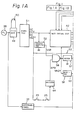
- Figures lA and 1B show a left half and a right half sides of the electric circuit block diagram, respectively, for schematically illustrating the connection of the driving motor controller of the robot and the switches 25.
- the driving motors 18 to 20 are, in this embodiment, DC servomotors.
- the driving motor controller generally denoted by reference numeral 27 comprises motor driving units 28 to 30 for driving the motors 18 to 20, respectively and speed controlling units 31 to 33 for controlling the rotational velocity of the output shafts of the motors 18 to 20, respectively.
- the motor driving units 28 to 30 are connected through electromagnetic switches 34 to 36, respectively, to a servotransformer 37 which is connected to a three-phase AC power source 38. Each of the motor driving units 28 to 30 transforms a three-phase AC voltage into a DC voltage.
- the electromagnetic switches 39 to 41 control the power supply to the motor driving units 28 to 30 from the power source 38 in accordance with the ON-OFF operation of operating switches 39 to 41.
- the driving motor controller 27 has a main control unit 42.
- the main control unit 42 transmits a normal rotation command signal, a reverse rotation command signal, or a stop command signal to the motor driving units 28 to 30 in accordance with a predetermined control program, in response to the detection signals given thereto from the position detectors 43 to 45, and also transmits a speed command signal to the speed controlling units 31 to 33.
- Speed detectors 46 to 48 for detecting the rotational velocity of the respective output shafts of the motors 18 to 20 transmit detecting signals to the speed controlling units 31 to 33, respectively, and the speed controlling units 31 to 33 control the level of the DC current to be supplied to the motors 18 to 20 from the motor driving units 28 to 30 on the basis of the speed command signals given thereto by the main control unit 42 and the speed detection signals given thereto by the speed detectors, respectively, to control the respective rotational velocity of the motors 18 to 20.
- the power source 38 is connected through an input unit 49 having a power switch 50 to a power unit 51.
- the power unit 51 supplies an operating voltage to the main control unit 42 when the power switch 50 is closed.
- a voltage comparator 52 namely, a voltage detector, detects whether the operating voltage supplied to the main control unit 42 from the power unit 51 has reached a reference voltage, for example, +5V DC, and provides an output signal VSB having a level 1 when the operating voltage coincides with the reference voltage.
- An operating unit 53 is provided with coils 54 to 56 for controlling the operating switches 39 to 41, respectively. The series connection of the coils 54 to 56 is connected at one end thereof to the output terminal of the power unit 51, and the other end thereof is grounded through a driver 57.
- the driver 57 is connected to the output terminal of a NAND gate 58.
- the driver 57 connects the coils 54 to 56 to the earth when the output level of the NAND gate 58 is 0 (zero) and disconnects the same from the earth when the output level of the NAND gate 58 is 1 (one).
- the output terminal of the voltage comparator 52 is connected to an input terminal of the NAND gate 56.
- An operation detecting circuit 59 has switches 60, 61, and 62 which are closed when the coils 54 to 56 are energized, respectively.
- One terminal of the series connection of the switches 60 to 62 is connected to the power unit 51, and the other terminal thereof is connected to the main controlling unit 42 through a receiver 63.
- a predetermined DC voltage for example, +24V DC
- One terminal of the series connection of the pressure switches 25 is connected to the power unit 51, and the other terminal thereof is connected to an input terminal of the NAND gate 58 through a receiver 64.
- the pressure switches 25 are closed while the pressure in the airtight chamber of the robot is higher than a predetermined level which is higher than an atmospheric pressure outside the robot, and are opened when the pressure in the airtight chamber drops below the predetermined level. While all the pressure switches 25 are closed, the receiver 64 supplies an output signal APR having a level 1 to the NAND gate 58. When any one of the pressure switches 25 is opened, the receiver 64 provides an output signal APR of level 0.
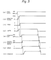
- FIG. 3 shows the mode of action of the driving motor controller and the safety device.
- the power switch 50 when the power switch 50 is closed, namely, in the ON-position (Fig.3 (a)), the operating voltage applied to the main controller 42 by the power unit 51 rises from the level 0 (Fig. 3 (b)).
- the voltage comparator 52 Upon the arrival of the operating voltage at the reference voltage (+5V DC), the voltage comparator 52 supplies an output signal VSB having a level 1 to the input terminal of the NAND gate 58 (Fig. 3 (c)).
- the receiver 64 supplies an output signal APR having a level 1 to the NAND gate 58 (Fig.
- the NAND gate 58 provides an output signal having a level 0, so that the operating unit 53 is actuated (Fig. 3 (e)). That is, when a NAND gate 58 supplies an output signal having a level 0 to the driver 57, the driver 57 connects the coils 54 to 56 to the earth, and thereby the coils 54 to 56 are energized.
- the operating switches 39 to 41 of the electromagnetic switches 34 to 36 are closed, respectively, and hence the respective electromagnetic switches 34 to 36 are closed, namely, in ON-positions (Fig. 3 (f)).
- the switches 60 to 62 of the operation detecting circuit 59 are closed, and hence an output signal VRDY from the receiver 63 is supplied to the main control unit 42 (Fig. 3 (g)).
- the main control unit 42 supplies predetermined command signals to the motor driving units 28 to 30 and the speed controllers 31 to 33, respectively, in accordance with the control program (Fig. 3 (h)).
- the DC servomotor contains an ignition sources, it is desirable to interrupt the supply of electric power to the motor driving units 28 to 30 from the power source instantaneously at the moment the pressure in the airtight chamber of the robot has dropped below the predetermined level. Since the supply of electric power to the motor driving units 28 to 30 is, in this embodiment, interrupted immediately after the pressure in the airtight chambers of the robot has dropped below the predetermined level, this embodiment is suitable for a robot employing DC servomotors as the robot driving motors.
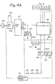
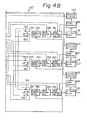
- Figure 4A and 4B show a left half side and a right half side of the block diagram, respectively, of the main part of the electric circuit of the industrial robot according to a second embodiment of the present invention.
- components similar or corresponding to those of the above-described embodiment are denoted by reference numerals which are higher than the reference numerals of the similar or corresponding components of the above-described embodiment by one hundred, respectively.
- Robot driving motors 118 to 120 are AC servomotors.
- Motor driving units 128 to 130 are adapted to apply a three-phase AC voltage to the driving motors 118 to 120 through speed controlling units 131 to 133, respectively.
- the motor driving units 128 to 130 act to change the rotational direction of and to stop the driving motors 118 to 120, respectively, in response to a signal given by the main control unit 142. Only the three robot driving motors 118 to 120 are shown in Figs. 4A and 4B, the rest of the robot driving motors are omitted to simplify the description.
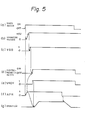
- FIG. 5 shows the mode of operation of the second embodiment.
- a power switch 150 Fig. 5 (a)
- the operating voltage supplied to the main controller 142 rises to a reference voltage (Fig. 5 (b))
- an output signal VSB of level 1 is given to the driver 157 of the operating unit 13 from the voltage comparator 152 (Fig. 5 (c)) to actuate the operating unit 153.
- electromagnetic switches 134 to 136 are changed to an ON-state (Fig. 5 (d)) and the switches 160 to 163 of an operation detecting circuit 159 are closed. Consequently, an output signal VRDY having a level 1 is supplied to the main control unit 142 from the receiver 163 (Fig.
- a pressure switch 25 or some other opens, and thereby the level of the output signal APR supplied by the receiver 164 to the main control unit 142 changes to level 0 (Fig. 5 (f)).
- the main control unit 142 acts to stop the robot in accordance with a control program in response to such a change of the level of the output signal APR. Since the AC servomotors 118 to 120 do not contain an ignition source, an emergency does not immediately result from the drop of pressure in the airtight chamber. Accordingly, the rotational speed of the driving motors may be reduced gradually in accordance with a control program before the driving motors are stopped, or the robot may be stopped after one cycle of the operation of the robot is finished.
- the speed control units and the motor driving units may be integrated as a single unit; the motor driving motors illustrated in Fig. 2 may be AC servomotors; and the driving motors for driving the wrist unit may be arranged within the forearm.
- the present invention can be applied to various industrial robots used in an inflammable or explosive environments for assembling operations or the like.
Landscapes
- Engineering & Computer Science (AREA)
- Robotics (AREA)
- Mechanical Engineering (AREA)
- Human Computer Interaction (AREA)
- Manufacturing & Machinery (AREA)
- Physics & Mathematics (AREA)
- General Physics & Mathematics (AREA)
- Automation & Control Theory (AREA)
- Manipulator (AREA)
- Numerical Control (AREA)
- Safety Devices In Control Systems (AREA)
Applications Claiming Priority (2)
| Application Number | Priority Date | Filing Date | Title |
|---|---|---|---|
| JP59137293A JPS6119593A (ja) | 1984-07-04 | 1984-07-04 | 内圧防爆ロボツトの安全装置 |
| JP137293/84 | 1984-07-04 |
Publications (3)
| Publication Number | Publication Date |
|---|---|
| EP0187865A1 true EP0187865A1 (de) | 1986-07-23 |
| EP0187865A4 EP0187865A4 (de) | 1987-03-05 |
| EP0187865B1 EP0187865B1 (de) | 1989-06-14 |
Family
ID=15195295
Family Applications (1)
| Application Number | Title | Priority Date | Filing Date |
|---|---|---|---|
| EP85903380A Expired EP0187865B1 (de) | 1984-07-04 | 1985-07-04 | Industrieller roboter |
Country Status (5)
| Country | Link |
|---|---|
| US (1) | US4706001A (de) |
| EP (1) | EP0187865B1 (de) |
| JP (1) | JPS6119593A (de) |
| DE (1) | DE3570997D1 (de) |
| WO (1) | WO1986000558A1 (de) |
Cited By (2)
| Publication number | Priority date | Publication date | Assignee | Title |
|---|---|---|---|---|
| EP0521204A1 (de) * | 1991-07-01 | 1993-01-07 | International Business Machines Corporation | Roboter-System |
| WO2017009162A3 (de) * | 2015-07-10 | 2017-03-16 | Waelischmiller Engineering Gmbh | Roboter-einrichtung mit einer angetriebenen einheit und aufbringverfahren |
Families Citing this family (26)
| Publication number | Priority date | Publication date | Assignee | Title |
|---|---|---|---|---|
| US6477913B1 (en) | 1985-01-22 | 2002-11-12 | Fanuc Robotics North America, Inc. | Electric robot for use in a hazardous location |
| US4984745A (en) * | 1985-01-22 | 1991-01-15 | Gmf Robotics Corporation | Electric robot for use in a hazardous location |
| JPS6263090A (ja) * | 1985-09-11 | 1987-03-19 | トキコ株式会社 | 電動ロボツトの防爆構造 |
| US5103404A (en) * | 1985-12-06 | 1992-04-07 | Tensor Development, Inc. | Feedback for a manipulator |
| FR2639053B1 (fr) * | 1988-11-15 | 1991-09-06 | France Etat Ponts Chaussees | Manipulateur pour engins de travaux publics et machine munie d'un tel manipulateur et servant au traitement d'une chaussee |
| DE4000348A1 (de) * | 1989-03-06 | 1990-09-13 | Hewlett Packard Co | Vorrichtung und verfahren zum ueberwachen der bewegungen eines vielgelenkigen roboters |
| JPH0366589A (ja) * | 1989-05-31 | 1991-03-22 | An Ey-Rang | ロボットの駆動制御回路 |
| US5293322A (en) * | 1989-10-24 | 1994-03-08 | Mitsubishi Denki Kabushiki Kaisha | Industrial robot apparatus |
| JP2716270B2 (ja) * | 1990-12-27 | 1998-02-18 | 株式会社日立製作所 | マニピュレ−タ |
| US6522096B1 (en) * | 1997-05-28 | 2003-02-18 | Kuka Roboter Gmbh | Control circuit for a robot power supply |
| JP2003311665A (ja) * | 2002-04-17 | 2003-11-05 | Yaskawa Electric Corp | ロボットシステム及び制御装置 |
| ITMI20051488A1 (it) * | 2005-07-29 | 2007-01-30 | Claudio Palombella | Apparato per l'alimentazione ed il controllo di apparecchi disposti in luoghi a rischio di esplosione e relativo dispositivo di controllo |
| WO2011084143A1 (en) * | 2009-12-21 | 2011-07-14 | Intrepid Robotics, Inc. | Methods for inspecting atmospheric storage tanks above ground and in floating vessels |
| US9901410B2 (en) | 2010-07-28 | 2018-02-27 | Medrobotics Corporation | Surgical positioning and support system |
| EP2629655B1 (de) | 2010-10-22 | 2018-12-19 | Medrobotics Corporation | In hohem masse bewegliche robotische sonden sowie verfahren zur herstellung und verwendung solcher sonden |
| KR101786832B1 (ko) | 2010-11-11 | 2017-10-18 | 메드로보틱스 코포레이션 | 고도 다관절 로봇 프로브용 도입 장치 및 그 생산 방법 |
| WO2013039999A2 (en) | 2011-09-13 | 2013-03-21 | Medrobotics Corporation | Highly articulated probes with anti-twist link arrangement, methods of formation thereof, and methods of performing medical procedures |
| WO2013096610A1 (en) | 2011-12-21 | 2013-06-27 | Oyola Arnold E | Stabilizing apparatus for highly articulated probes with link arrangement, methods of formation thereof, and methods of use thereof |
| AU2013299440A1 (en) | 2012-08-09 | 2015-03-05 | Medrobotics Corporation | Surgical tool positioning systems |
| US9913695B2 (en) | 2013-05-02 | 2018-03-13 | Medrobotics Corporation | Robotic system including a cable interface assembly |
| US10004568B2 (en) | 2013-12-30 | 2018-06-26 | Medrobotics Corporation | Articulating robotic probes |
| US10576620B1 (en) | 2016-04-08 | 2020-03-03 | Ikutuki | Robotic mobility device and control |
| JP6870154B2 (ja) | 2017-12-15 | 2021-05-12 | タンクボッツ,インコーポレーテッド | 危険物質を格納するタンク内でタスクを実行するための方法 |
| USD874655S1 (en) | 2018-01-05 | 2020-02-04 | Medrobotics Corporation | Positioning arm for articulating robotic surgical system |
| EP3928091A1 (de) | 2019-02-20 | 2021-12-29 | Tankbots, Inc. | Verfahren zur inhärent sicheren durchführung von aufgaben in einem behälter, der gefährliche substanzen enthält |
| JP2026518860A (ja) * | 2023-05-17 | 2026-06-10 | アーベーベー・シュバイツ・アーゲー | 産業システム及び産業システムの制御方法 |
Family Cites Families (13)
| Publication number | Priority date | Publication date | Assignee | Title |
|---|---|---|---|---|
| JPS516951B1 (de) * | 1970-12-23 | 1976-03-03 | ||
| JPS4731147A (de) * | 1971-03-29 | 1972-11-10 | ||
| JPS5321716Y2 (de) * | 1971-12-29 | 1978-06-07 | ||
| DE2228598A1 (de) * | 1972-06-12 | 1974-01-03 | Jens Dr Rer Nat Geerk | Anthropomorpher manipulator |
| US3952759A (en) * | 1974-08-14 | 1976-04-27 | M & J Valve Company | Liquid line break control system and method |
| JPS5187743A (de) * | 1975-01-30 | 1976-07-31 | Mitsui Shipbuilding Eng | |
| US4149935A (en) * | 1977-03-25 | 1979-04-17 | Westinghouse Electric Corp. | Pressurized cabling and junction boxes for nuclear reactor vessel inspection apparatus |
| JPS5518962A (en) * | 1978-07-27 | 1980-02-09 | Hitachi Ltd | Device for detecting in nuclear reactor vessel |
| GB2038772B (en) * | 1978-11-30 | 1982-08-11 | Atomic Energy Authority Uk | Sealing devices |
| US4587619A (en) * | 1981-12-14 | 1986-05-06 | Scans Associates, Inc. | Method and apparatus for electronic leak testing |
| US4398233A (en) * | 1982-03-03 | 1983-08-09 | Electronics Corporation Of America | Fail-safe device for electronic control circuit |
| GB2127775B (en) * | 1982-09-27 | 1985-10-16 | Gen Electric Co Plc | Controlled machine limb incorporating a safety coupling |
| US4575610A (en) * | 1984-03-12 | 1986-03-11 | Cincinnati Milacron Inc. | Laser shielding device |
-
1984
- 1984-07-04 JP JP59137293A patent/JPS6119593A/ja active Pending
-
1985
- 1985-07-04 WO PCT/JP1985/000378 patent/WO1986000558A1/ja not_active Ceased
- 1985-07-04 DE DE8585903380T patent/DE3570997D1/de not_active Expired
- 1985-07-04 EP EP85903380A patent/EP0187865B1/de not_active Expired
- 1985-07-04 US US06/845,276 patent/US4706001A/en not_active Expired - Lifetime
Cited By (2)
| Publication number | Priority date | Publication date | Assignee | Title |
|---|---|---|---|---|
| EP0521204A1 (de) * | 1991-07-01 | 1993-01-07 | International Business Machines Corporation | Roboter-System |
| WO2017009162A3 (de) * | 2015-07-10 | 2017-03-16 | Waelischmiller Engineering Gmbh | Roboter-einrichtung mit einer angetriebenen einheit und aufbringverfahren |
Also Published As
| Publication number | Publication date |
|---|---|
| EP0187865B1 (de) | 1989-06-14 |
| US4706001A (en) | 1987-11-10 |
| EP0187865A4 (de) | 1987-03-05 |
| WO1986000558A1 (fr) | 1986-01-30 |
| JPS6119593A (ja) | 1986-01-28 |
| DE3570997D1 (en) | 1989-07-20 |
Similar Documents
| Publication | Publication Date | Title |
|---|---|---|
| EP0187865B1 (de) | Industrieller roboter | |
| US4730861A (en) | Finger gripper with state indicator | |
| EP0187862A1 (de) | Industrieller roboter | |
| US20230418258A1 (en) | Multifunctional input device for a robot arm | |
| US6585246B2 (en) | Electric clamp | |
| US4865514A (en) | Manipulator system with small arm removably attachable at points along large arm | |
| US4922436A (en) | Method and system for the automated driving of parts and device used therein | |
| US5783922A (en) | Robot controller permitting lead-through teaching | |
| EP1278977B1 (de) | Elektrischer stellantrieb für fluidsteuerventile | |
| US4931711A (en) | Industrial robot control apparatus | |
| EP0242867A3 (de) | Robotersteuergerät | |
| CA2219293A1 (en) | Power conversion system for bi-directional conversion between hydraulic energy and electrical energy | |
| CN113829384B (zh) | 一种机械臂关节模组及其机械臂 | |
| EP0391216B1 (de) | Direktanlernbarer Roboter | |
| JP5863419B2 (ja) | 内圧防爆構造を有する多関節ロボットの制御システム及び方法 | |
| US4261509A (en) | Pneumatic switch control for pneumatic actuator in air conditioning control systems | |
| US4816728A (en) | Photoelectric motion limiting control apparatus for a robot mechanism | |
| EP0965417A2 (de) | Roboter Steuerungssystem | |
| EP0229185B1 (de) | Industrieller roboter | |
| EP0062070A1 (de) | Vorrichtung zum betrieb einer hand eines industriellen roboters | |
| US4985653A (en) | Internal pressure explosion-proof construction for electrically-driven robot | |
| KR19990008464A (ko) | 차량내에 설치된 조정 구동부의 전자적 감시장치 및 그 방법 | |
| GB2127775A (en) | Controlled machine limb incorporating a safety coupling | |
| JP2608643B2 (ja) | 塗装ロボット | |
| JPH0577183A (ja) | ロボツトの制御装置 |
Legal Events
| Date | Code | Title | Description |
|---|---|---|---|
| PUAI | Public reference made under article 153(3) epc to a published international application that has entered the european phase |
Free format text: ORIGINAL CODE: 0009012 |
|
| 17P | Request for examination filed |
Effective date: 19860324 |
|
| AK | Designated contracting states |
Kind code of ref document: A1 Designated state(s): DE GB |
|
| A4 | Supplementary search report drawn up and despatched |
Effective date: 19870305 |
|
| 17Q | First examination report despatched |
Effective date: 19880920 |
|
| GRAA | (expected) grant |
Free format text: ORIGINAL CODE: 0009210 |
|
| AK | Designated contracting states |
Kind code of ref document: B1 Designated state(s): DE GB |
|
| REF | Corresponds to: |
Ref document number: 3570997 Country of ref document: DE Date of ref document: 19890720 |
|
| PGFP | Annual fee paid to national office [announced via postgrant information from national office to epo] |
Ref country code: DE Payment date: 19890829 Year of fee payment: 5 |
|
| PLBI | Opposition filed |
Free format text: ORIGINAL CODE: 0009260 |
|
| 26 | Opposition filed |
Opponent name: ASEA BROWN BOVERI AB Effective date: 19900313 |
|
| PGFP | Annual fee paid to national office [announced via postgrant information from national office to epo] |
Ref country code: GB Payment date: 19900622 Year of fee payment: 6 |
|
| RDAG | Patent revoked |
Free format text: ORIGINAL CODE: 0009271 |
|
| STAA | Information on the status of an ep patent application or granted ep patent |
Free format text: STATUS: PATENT REVOKED |
|
| 27W | Patent revoked |
Effective date: 19901001 |
|
| GBPR | Gb: patent revoked under art. 102 of the ep convention designating the uk as contracting state |