EP0191422A2 - Zuführvorrichtung für Artikel - Google Patents
Zuführvorrichtung für Artikel Download PDFInfo
- Publication number
- EP0191422A2 EP0191422A2 EP86101562A EP86101562A EP0191422A2 EP 0191422 A2 EP0191422 A2 EP 0191422A2 EP 86101562 A EP86101562 A EP 86101562A EP 86101562 A EP86101562 A EP 86101562A EP 0191422 A2 EP0191422 A2 EP 0191422A2
- Authority
- EP
- European Patent Office
- Prior art keywords
- drum
- outer peripheral
- products
- peripheral surface
- pockets
- Prior art date
- Legal status (The legal status is an assumption and is not a legal conclusion. Google has not performed a legal analysis and makes no representation as to the accuracy of the status listed.)
- Withdrawn
Links
- 230000002093 peripheral effect Effects 0.000 claims abstract description 37
- 239000000825 pharmaceutical preparation Substances 0.000 claims abstract description 19
- 229940127557 pharmaceutical product Drugs 0.000 claims abstract description 19
- 239000007787 solid Substances 0.000 claims abstract description 16
- 238000012545 processing Methods 0.000 abstract description 4
- 238000007689 inspection Methods 0.000 description 8
- XEEYBQQBJWHFJM-UHFFFAOYSA-N Iron Chemical compound [Fe] XEEYBQQBJWHFJM-UHFFFAOYSA-N 0.000 description 4
- 238000012986 modification Methods 0.000 description 4
- 230000004048 modification Effects 0.000 description 4
- 239000007902 hard capsule Substances 0.000 description 3
- 239000007901 soft capsule Substances 0.000 description 3
- 239000000428 dust Substances 0.000 description 2
- 229910052742 iron Inorganic materials 0.000 description 2
- 230000000717 retained effect Effects 0.000 description 2
- 230000005540 biological transmission Effects 0.000 description 1
- 238000004891 communication Methods 0.000 description 1
- 238000010276 construction Methods 0.000 description 1
- 230000001627 detrimental effect Effects 0.000 description 1
- 238000011161 development Methods 0.000 description 1
- 230000000694 effects Effects 0.000 description 1
- 230000005484 gravity Effects 0.000 description 1
- 230000001771 impaired effect Effects 0.000 description 1
- 239000006187 pill Substances 0.000 description 1
- 230000002028 premature Effects 0.000 description 1
- 238000000926 separation method Methods 0.000 description 1
- 230000001360 synchronised effect Effects 0.000 description 1
- 239000003826 tablet Substances 0.000 description 1
- 238000012546 transfer Methods 0.000 description 1
Images



Classifications
-
- B—PERFORMING OPERATIONS; TRANSPORTING
- B65—CONVEYING; PACKING; STORING; HANDLING THIN OR FILAMENTARY MATERIAL
- B65G—TRANSPORT OR STORAGE DEVICES, e.g. CONVEYORS FOR LOADING OR TIPPING, SHOP CONVEYOR SYSTEMS OR PNEUMATIC TUBE CONVEYORS
- B65G47/00—Article or material-handling devices associated with conveyors; Methods employing such devices
- B65G47/02—Devices for feeding articles or materials to conveyors
- B65G47/04—Devices for feeding articles or materials to conveyors for feeding articles
- B65G47/12—Devices for feeding articles or materials to conveyors for feeding articles from disorderly-arranged article piles or from loose assemblages of articles
- B65G47/14—Devices for feeding articles or materials to conveyors for feeding articles from disorderly-arranged article piles or from loose assemblages of articles arranging or orientating the articles by mechanical or pneumatic means during feeding
- B65G47/1407—Devices for feeding articles or materials to conveyors for feeding articles from disorderly-arranged article piles or from loose assemblages of articles arranging or orientating the articles by mechanical or pneumatic means during feeding the articles being fed from a container, e.g. a bowl
- B65G47/1442—Devices for feeding articles or materials to conveyors for feeding articles from disorderly-arranged article piles or from loose assemblages of articles arranging or orientating the articles by mechanical or pneumatic means during feeding the articles being fed from a container, e.g. a bowl by means of movement of the bottom or a part of the wall of the container
- B65G47/1457—Rotating movement in the plane of the rotating part
Definitions
- the present invention generally relates to an article supply apparatus and, more particularly, to the apparatus for supplying articles of identical shape, for example, solid pharmaceutical products such as tablets, pills or hard or soft capsules, in predetermined position or posture in readiness for the successive transfer of the articles onto an article handling device.
- articles of identical shape for example, solid pharmaceutical products such as tablets, pills or hard or soft capsules
- a rotary drum is generally utilized of a type having a cylindrical outer peripheral surface formed, or provided, with at least one circumferentially extending row of circumferentially and radially equally spaced receptacles each for the support of the respective tablet by the effect of a suction force during the transportation thereof.
- the receptacles on the drum disclosed in any one of the above mentioned U.S.
- patents are each in the form of a radially inwardly recessed receptacle having a shape similar to the contour of the tablet handled thereby and are adapted to be communicated with a source of vacuum for sucking the respective tablets only during the transportation from the supply station to a position a slight distance preceding the subsequent processing station.
- the drum rotated continuously in one direction receives the tablets from a generally bottomless hopper having its open bottom overhanging and receiving therein a portion of the outer periphery of the drum so that some of the tablets which happen to sit in the respective receptacles can be sucked and retained therein for the transportation.
- a conventional tablet aligning apparatus utilizing the drum of the above described type in combination with the above described hopper has a handling capacity generally limited to about 400 tablets per minute at most while it has a problem in that a number of the tablets tend to be impaired at a location between the drum and the hopper.
- the present invention has been developed with a view to satisfying the need in the pharmaceutical field and has for its essential object to provide an improved article aligning device capable of delivering solid pharmaceutical products successively at high speed, for example, at a rate of 3600 tablets per minute, while the articles are aligned in predetermined position.
- the present invention provides an article supply apparatus for solid pharmaceutical products each having a uniform length, a uniform width and a uniform thickness which are randomly supplied into a hopper rotatable together with a rotary drum and which are successively taken out from the drum at a predetermined position adjacent an outer peripheral edge of the drum while having been aligned in predetermined posture, said drum having its outer peripheral surface being tapered with its axis inclined at a predetermined angle, a lower region of the outer peripheral surface having a plurality of radial projections of predetermined height so formed thereon and so spaced an approximately predetermined pitch from each other that product receiving pockets each having a width slightly greater than the thickness of each product can be formed on that lower region of the outer peripheral surface of the drum, said hopper being mounted on the drum while a lower region of the hopper is spaced from the outer peripheral surface of the drum a distance slightly greater than the thickness of each product so as to extend substantially parallel to the outer peripheral surface of the drum and exteriorly covers at least respective portions of the product receiving pockets,
- the length of each of the product receiving pockets is selected to be an integral multiple of the length of each product so that the products can be successfully inserted into the respective pockets without the occurrence of bridging of the products.
- An article supply apparatus is so designed and so constructed as to randomly supply a plurality of solid pharmaceutical products so standardized as to have a predetermined length, width and thickness (it being however that the thickness is smaller than the width which is in turn equal to or smaller than the length), and as to pick up the products individually, i.e., one at a time, while they have been aligned in a predetermined posture.
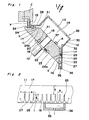
- the article supply apparatus for the solid pharmaceutical products A comprises an inclined drive shaft 10 adapted to be driven by an electric motor E, a transport drum 11 of frusto-conical shape detachably mounted on the drive shaft 10, and a generally cylindrical hollow hopper 12 rigidly mounted on the transport drum 11 for rotation together therewith.
- the hopper 12 has a hopper chamber 14 defined therein and also a supply opening defined therein at 13 in communication with the hopper chamber 14.
- the transport drum 11 has a plurality of product receiving pockets 16 which can be successively brought to a pick-up station 15 during the rotation of the drum 11 in one direction and also an aligning room 17 defined between the drum 11 and the hopper 12.
- the transport drum 11 has a shape generally similar to a truncated right circular cone having its base formed with a mounting hole 18 in alignment with the axis thereof.
- the base of the transport drum 11 is formed with a pin socket 21 for receiving therein a connecting pin 20, which is rigidly mounted on an annular flange 19 rigid or integral with the drive shaft 10, and is provided with an iron piece 23 adapted to be magnetically attracted by a magnet 22 rigidly mounted on the annular flange 19.
- An outer peripheral surface of the transport drum 11 tapering in a direction from the base of the drum 11 towards the flat top thereof is, as best shown in Fig. 2, formed with a plurality of radial projections 25 spaced circumferentially at intervals of a predetermined pitch P from each other and extending from the base of the drum 11 and terminating at a location generally intermediate of the width of the outer peripheral surface of the drum 11.
- Each neighboring projections 25 define the respective pocket 16 referred to hereinbefore.
- Each of the projections 25 has a height h slightly greater than the thickness of each solid pharmaceutical product (for example, by 1 mm), and a length A equal to an integral multiple of, for example, twice, the length of the respective product while the spacing s between each neighboring projections 25 is slightly greater than the width of the respective product (for example, by 1 mm), so that each of the pockets 16 can accommodate two solid pharmaceutical products one above the other with the widthwise and thicknesswise directions of each of the products oriented towards the neighboring projections 25 and the outer peripheral surface of the drum 11, i.e., the bottom of the respective pocket 16, respectively, the upper one of the solid pharmaceutical products in each pocket 16 being positioned inwardly of the pocket with respect to the level extending in touch with the free ends of each neighboring projections 25.
- Each of the projections 25 has a predetermined width r which may be, for example, 1 mm and which may be so selected that the pockets 16 can be formed on the outer peripheral surface of the drum 11 at the approximately predetermined pitch p.
- Lower ends of the respective projections 25 are so continued through runners 26 to each other that no products received in the pockets 16 will not fall down from the pockets 16, each of said runners 26 being formed with a fine groove 27 for the downward passage by gravity of dust and fine particulates of the solid pharmaceutical products out of the respective pocket 16.
- An upper portion of the outer peripheral surface of the drum 11 clear from the projections 25 serves as a slide surface having a width q greater than the length of each solid pharmaceutical product so that the products can freely slide therealong in a direction circumferentially of the drum 11.
- the hopper 12 comprises a generally cylindrical hollow body 30 having one end closed by an end plate having the supply opening 13 defined therein, and an annular outwardly flared flange 28 protruding outwardly from the opposite end of the hollow body 30 so as to flare radially outwardly following the shape of the drum 11.
- the hopper 12 is mounted on the drum 11 for rotation together therewith and, for this purpose, the flared flange 28 is secured to some of the projections 25 by means of set screws 29 with the aligning room 17 formed between the outer peripheral surface of the drum 11 and the inner peripheral surface of the flared flange 28, said aligning room 17 being delimited by a spacing h which is slightly greater than the thickness of each of the solid pharmaceutical products.
- the width of the flared flange 28 is so selected that it can cover not only that portion of the outer peripheral surface of the drum which forms the slide surface, but also respective portions of the pockets 16 so that the products received in each pocket 16 will not fall down therefrom.
- the aligning room 17 serves to guide each product into the associated pocket 16 with the thicknesswise direction of said product oriented perpendicular to the outer peripheral surface of the drum 11, while permitting the products to move freely in a direction widthwise and lengthwise of each product.
- the cylindrical hollow body 30 has a plurality of spaced scooper blades 32 secured to the inner peripheral surface thereof adjacent the flared flange 28 so as to protrude radially inwardly.
- An annular guide plate 33 so tapered as to follow the shape of the transport drum 11 is fixedly supported on one side of the flared flange 28 remote from the body 30 and exteriorly around the drum 11 so as to cover the remaining portions of the pockets 16 not covered by the flared flange 28.
- a portion of the guide plate 33 in register with the pick-up station 15 is cut out to provide a pick-up port 34 through which the products successively transported to the pick-up station 15 during the rotation of the drum 11 can be removed out of the associated pockets 16.
- a vacuum ring 35 Positioned beneath the guide plate 33 is a vacuum ring 35 having a suction passage 36 which communicates with the fine grooves 27 in the runners 26 for sucking dust and fine particulates out from the pockets 16.
- the hopper 12 is substantially coaxially fixed to the transport drum 11 and is in turn detachably mounted substantially coaxially on the drive shaft 10 together with the drum 11. Since the drive shaft 10 is so supported as to incline in a vertical plane at the predetermined angle, the outer peripheral surface of the drum 11 mounted on such drive shaft 10 is also inclined.
- a portion 24a of the outer peripheral surface of the drum 11 can lie generally in a vertical plate while the opposite portion 24b of the same spaced 180° from that portion 24a about the shaft 10 can lie in a plane perpendicular to the plane in which that portion 24a lies, as shown in Fig. 1. Accordingly, as the transport drum 11 is rotated together with the drive shaft 10, some of the pockets 16 are successively oriented downwards while some of the pockets are at the same time successively oriented horizontally as shown in Fig.
- the products so received into the pockets 16 are, during the continued rotation of the drum 11, successively transported towards the pick-up station 15 at which one of the two products in each pocket 16 which is positioned adjacent the respective runner 26 is picked out from such pocket 16 through the pick-up port 34 in the annular guide plate 33.
- the transport drum 11 is further rotated, the products, two in one pocket 16, are successively transported towards the pick-up station 15 at which the products A are laid horizontally in readiness for the removal thereof from the associated pockets 16.
- Each of the products A removed from the pocket 16 at the pick-up station 15 is delivered onto an inspection drum C shown in Fig. 3 so that it can be passed in front of an inspection camera D for the inspection of the product.
- the inspection drum and the transport drum are driven in synchronism with each other by means of a drive transmission system E including a set of bevel gears, pulleys and an endless belt or chain.
- the inspection drum C has a plurality of suction nozzles F spaced from each other a distance equal to the pitch between the neighboring pockets 16, each of said suction nozzles F being adapted to suck the product A out from the associated pocket 16 at the pick-up station 15 for the transportation thereof towards an inspection station where the camera D is installed.
- the inspection of the products may be for any desired purpose, for example, for determining whether or not each product has any detrimental flaw.
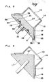
- the drive shaft 10 has been shown and described as received in the mounting hole in the drum.
- the connection between the drum 11 and the drive shaft 10 may not be always limited thereto, but may be in any manner.
- the drive shaft 10 has a disc 19 rigidly mounted thereon and fixed thereto by means of at least one set bolt 38.
- the disc 19 is received in a circular recess 39 defined in the base of the drum 11.
- the scooper blades 34 which have been described as secured to the hopper in the foregoing embodiment of Figs. 1 to 4 are shown as secured to the flat top 37 of the drum 11.
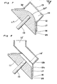
- the drum 11 may not be always frusto-conical in shape as best shown in Fig. 1, but may be conical as shown in Fig. 6, in which case an apex portion 37' is situated within the cylindrical hollow body 30 of the hopper 12, or generally conical with its apex area rounded as shown by 37'' in Fig. 7.
- the hopper 12 comprises an annular flared member 12a, similar to the flared flange 28 employed in the foregoing embodiments, which member 12a is secured to the drum 11 for rotation together therewith.
- the hopper also comprises a guide chute 12b having one end opened to provide a supply opening 13' and the other end opened to communicate with a chamber 14' inside the flared member 12a.
- the hopper shown in Fig. 8 is of two-piece construction with the flared member 12a and the guide chute 12b rotatable and stationary, respectively.
- the transport drum may be of a shape similar to a multilateral pyramid as shown by 11"', in which case the body of the hopper defining the chamber 14 has a polygonal cross-section as shown by 12''' and likewise the flared flange is similar in shape to the cross-sectional representation of the drum 11''' as shown by 28'''.
- the supply device according to the embodiment of Fig. 9 can function in a manner similar to that according to the embodiment of Figs. 1 to 4, it being, however, that, if the drum 11''' is intermittently rotated, the removal of the product from the associated pockets can be easily performed at the pick-up station.
- the pick-up port which, in the embodiment of Figs. 1 to 4, has been described as formed in the guide plate 33 at a location in register with some of the pockets 16 then laid horizontally is formed, as shown by 34', in the guide plate 33 at a location in register with some of the pockets 16 then laid vertically downwards so that the products A can be successively removed from the associated pockets 16 in a direction downwards.
- the removal of the products from the pockets is carried out with the aid of a star wheel G arranged below the outer peripheral surface of the drum 11 adjacent the pick-up port 34' and driven in synchronized relationship with the rotation of the drum 11, said star wheel having, as best shown in Fig. 11, a plurality of circumferentially equally spaced recesses Ga each capable of receiving one product A for the transportation towards a subsequent processing station.
- a lower peripheral edge portion of the drum 11 is formed with a plurality of suction passages 42 equal in number to the pockets 16 in the drum 11, each of said suction passages 42 having one end opening into the respective pocket 16 at a location aligned with the product next to the product ready to be removed by the star wheel G.
- the opposite ends of the respective suction passages 42 open in the base of the drum 11 in circular configuration concentric with the axis of rotation of the drum 11.
- suction passages 42 are selectively communicated with a source of vacuum during each rotation of the drum 11 through a suction pocket 41 defined in a back-up plate 40 in alignment with the path of movement of the opposite ends of the passages 42.
- the back-up plate 40 is stationarily supported and is normally urged in one direction so as to slidingly contact the base of the drum 11.
- the suction pocket 41 in the back-up plate is so formed and so positioned as to communicate with the vacuum source of one of the pockets 16 which is then aligned with the pick-up station whereby the lower and upper products accommodated in said one of the pockets can be permitted to leave such one of the pockets onto the star wheel G and to be retained therein, respectively.
- the guide plate 33 positioned radially exteriorly of the pockets serves to avoid the premature separation of the products from the associated pockets except for the one then aligned with the pick-up station.
- Fig. 12 is a view similar to Fig. 2, showing a modification of the pockets. As shown, the free end of each of the projections 25 is chamferred to facilitate the entry of any one of the products into the respective pocket 16.
- the products which the apparatus according to the present invention can handle include various types of tablets as shown in Figs. 13 (a) and 13(b), Figs. 14 (a) and 14 (b), Figs. 15 (a) and 15(b), and Figs. 16(a) and 16(b), respectively, hard capsules as shown in Fig. 17, and soft capsules as shown in Fig. 18.
- the solid pharmaceutical product which the apparatus according to the present invention can handle is of a type having a length, a width and a thickness.
- each of the pockets in the transport drum are to be selected in consideration of the size of each of the pharmaceutical products to be handled by the apparatus according to the present invention.
- the transport drum has been described as detachably mounted on the inclined drive shaft.
- This arrangement is particularly advantageous in that the transport drum per se can be cleaned or repaired separate from the machine proper and in that a single machine can be used to accommodate different types of pharmaceutical products merely by replacing one transport drum with another transport drum having different pockets.
- the transport drum may not always be detachably mounted on the inclined drive shaft, but may be rigidly mounted thereon.
Landscapes
- Engineering & Computer Science (AREA)
- Mechanical Engineering (AREA)
- Feeding Of Articles To Conveyors (AREA)
- Specific Conveyance Elements (AREA)
- Branching, Merging, And Special Transfer Between Conveyors (AREA)
Applications Claiming Priority (2)
| Application Number | Priority Date | Filing Date | Title |
|---|---|---|---|
| JP60028087A JPH066442B2 (ja) | 1985-02-14 | 1985-02-14 | 固形製剤の供給装置 |
| JP28087/85 | 1985-02-14 |
Publications (2)
| Publication Number | Publication Date |
|---|---|
| EP0191422A2 true EP0191422A2 (de) | 1986-08-20 |
| EP0191422A3 EP0191422A3 (de) | 1987-03-25 |
Family
ID=12238997
Family Applications (1)
| Application Number | Title | Priority Date | Filing Date |
|---|---|---|---|
| EP86101562A Withdrawn EP0191422A3 (de) | 1985-02-14 | 1986-02-06 | Zuführvorrichtung für Artikel |
Country Status (3)
| Country | Link |
|---|---|
| US (1) | US4673077A (de) |
| EP (1) | EP0191422A3 (de) |
| JP (1) | JPH066442B2 (de) |
Cited By (2)
| Publication number | Priority date | Publication date | Assignee | Title |
|---|---|---|---|---|
| CN107973099A (zh) * | 2017-11-05 | 2018-05-01 | 安徽康乐机械科技有限公司 | 边框卸载机 |
| EP4559846A1 (de) * | 2023-11-24 | 2025-05-28 | Enclony Inc | Zentrifugalzuführer und tablettenprüfvorrichtung damit |
Families Citing this family (19)
| Publication number | Priority date | Publication date | Assignee | Title |
|---|---|---|---|---|
| JP2897801B2 (ja) * | 1993-03-18 | 1999-05-31 | シオノギクオリカプス株式会社 | 直径に比べて小さい厚みをもつ円板状固形製剤の搬送装置 |
| DE19511854A1 (de) * | 1994-08-11 | 1996-02-15 | Graessle Walter Gmbh | Vorrichtung und Verfahren zum Prüfen von kleinen Gegenständen |
| US5826696A (en) * | 1994-08-11 | 1998-10-27 | Walter Grassle Gmbh | Apparatus for separating small articles |
| US5540317A (en) * | 1995-01-17 | 1996-07-30 | Chipstar, Inc. | Machine to detect and process to correct capacitor chip misalignment in loading for processing |
| US5863331A (en) * | 1996-07-11 | 1999-01-26 | Braden; Denver | IPC (Chip) termination machine |
| US5984079A (en) * | 1996-07-12 | 1999-11-16 | Electro Scientific Industries, Inc. | Method and apparatus for loading electronic components |
| US6446783B1 (en) * | 2000-06-30 | 2002-09-10 | General Electric Company | Electrode tip loading method and apparatus |
| US6367611B1 (en) * | 2000-08-22 | 2002-04-09 | General Electric Company | Part feeding system |
| KR20050005463A (ko) * | 2002-06-21 | 2005-01-13 | 이코스비젼 시스템즈, 남로제 베노차프 | 경사진 공급 트랙으로부터 다른 부재로 전자 부품을이송하는 장치 |
| CN100377971C (zh) * | 2004-08-30 | 2008-04-02 | 北京万江科技有限公司 | 一种锥面转鼓输送机构 |
| US7757835B2 (en) * | 2007-12-05 | 2010-07-20 | Philip Moris Usa Inc. | Bead feeder |
| EP2316582B1 (de) * | 2009-11-02 | 2014-01-22 | Sontec AG | Verfahren und Vorrichtung zur optischen Prüfung von Werkstücken |
| US8733535B2 (en) * | 2011-06-17 | 2014-05-27 | Electro Scientific Industries, Inc. | Shallow angle vertical rotary loader for electronic device testing |
| KR101738404B1 (ko) * | 2015-04-17 | 2017-05-24 | (주)엔클로니 | 정제 검사 장치 |
| DE102015109387A1 (de) * | 2015-06-12 | 2016-12-15 | Thilo Kraemer | Vorrichtung zur Vereinzelung von Prüflingen |
| US10006974B2 (en) * | 2015-09-22 | 2018-06-26 | Apple Inc. | Automated system for magnet quality measurements |
| US10683114B2 (en) * | 2017-02-24 | 2020-06-16 | Taiyo Yuden Co., Ltd. | Taping apparatus |
| JP6901931B2 (ja) * | 2017-02-24 | 2021-07-14 | 太陽誘電株式会社 | テーピング装置 |
| JP7061490B2 (ja) * | 2018-03-22 | 2022-04-28 | 株式会社Screenホールディングス | 搬送装置および搬送方法 |
Family Cites Families (20)
| Publication number | Priority date | Publication date | Assignee | Title |
|---|---|---|---|---|
| US845415A (en) * | 1905-03-31 | 1907-02-26 | James M Hicks | Cap-feeding machine. |
| US887298A (en) * | 1906-09-22 | 1908-05-12 | John T Wilmore | Means for turning and arranging can-caps and other closures. |
| US1922425A (en) * | 1930-10-25 | 1933-08-15 | Hughes Tool Co | Device for registering and feeding objects to alpha magazine |
| US2538706A (en) * | 1947-08-26 | 1951-01-16 | Remington Arms Co Inc | Article arranging |
| US2916165A (en) * | 1957-02-25 | 1959-12-08 | United Shoe Machinery Corp | Mechanisms for feeding disk-type capacitors and like articles |
| US3042183A (en) * | 1959-04-03 | 1962-07-03 | Hartnett Co R W | Article handling apparatus |
| US3015378A (en) * | 1959-08-19 | 1962-01-02 | Hansella Werke Albert Henkel A | Orientation apparatus for articles to be wrapped |
| US3215251A (en) * | 1964-01-02 | 1965-11-02 | American Home Prod | Apparatus for aligning and orienting elongate cylindrical objects |
| US3318434A (en) * | 1965-03-16 | 1967-05-09 | Waller Willy | Apparatus for the automatic feed of pull-off closures |
| GB1297083A (de) * | 1970-06-23 | 1972-11-22 | ||
| US3650368A (en) * | 1970-11-30 | 1972-03-21 | Nalbach Eng Co J | Article-orienting apparatus |
| US3889591A (en) * | 1972-11-28 | 1975-06-17 | Takeda Chemical Industries Ltd | Method and apparatus for printing indicia on products |
| CH596064A5 (en) * | 1975-04-17 | 1978-02-28 | Prontor Werk Gauthier Gmbh | Disc shaped workpiece transport mechanism |
| US3986636A (en) * | 1975-04-17 | 1976-10-19 | Hoppmann Corporation | High speed method for translating articles from in-line array to side by side array |
| JPS5296195A (en) * | 1976-02-04 | 1977-08-12 | Osaka Jidouki Seisakushiyo Kk | Rotary apparatus for reeorientating and charging capsules |
| DE2651495C2 (de) * | 1976-11-11 | 1983-03-31 | Rationator-Maschinenbau Gmbh, 6521 Hillesheim | Vorrichtung zum Aufrichten und Aufreihen von Flaschen, Dosen, Formteilen oder dergleichen |
| CH619190A5 (en) * | 1977-02-14 | 1980-09-15 | John Walter Hoehn | Device for the alignment of objects |
| DE2754189A1 (de) * | 1977-12-06 | 1979-10-18 | Karl Heinz Baer | Einrichtung zum sortieren von kleinteilen |
| CH642174A5 (de) * | 1978-03-17 | 1984-03-30 | Fuji Electric Co Ltd | Einrichtung zur kontrolle des aussehens von festkoerpermedikamenten. |
| US4279336A (en) * | 1980-01-28 | 1981-07-21 | The Regents Of The University Of California | Singulator |
-
1985
- 1985-02-14 JP JP60028087A patent/JPH066442B2/ja not_active Expired - Lifetime
-
1986
- 1986-02-03 US US06/825,267 patent/US4673077A/en not_active Expired - Fee Related
- 1986-02-06 EP EP86101562A patent/EP0191422A3/de not_active Withdrawn
Cited By (2)
| Publication number | Priority date | Publication date | Assignee | Title |
|---|---|---|---|---|
| CN107973099A (zh) * | 2017-11-05 | 2018-05-01 | 安徽康乐机械科技有限公司 | 边框卸载机 |
| EP4559846A1 (de) * | 2023-11-24 | 2025-05-28 | Enclony Inc | Zentrifugalzuführer und tablettenprüfvorrichtung damit |
Also Published As
| Publication number | Publication date |
|---|---|
| EP0191422A3 (de) | 1987-03-25 |
| US4673077A (en) | 1987-06-16 |
| JPH066442B2 (ja) | 1994-01-26 |
| JPS61188318A (ja) | 1986-08-22 |
Similar Documents
| Publication | Publication Date | Title |
|---|---|---|
| US4673077A (en) | Article supply apparatus | |
| EP0578602B1 (de) | Einrichtung zum automatischen Positionieren und Ausrichten von Behältern | |
| KR100354860B1 (ko) | 가볍고,속이빈,긴물품들을정렬하여일렬로운반하는자동설비 | |
| US6227345B1 (en) | Transfer apparatus of chip components | |
| US5853078A (en) | Vibrating feeder bowl with annular rotating disk feeder | |
| JPH01247042A (ja) | 糖菓の選別送置 | |
| US20090139836A1 (en) | Apparatus and Process for Unscrambling and Aligning Bulk Plastic Containers | |
| JPH0565405B2 (de) | ||
| US3826405A (en) | Method of orienting articles | |
| JPS59115145A (ja) | 螺子類の自動供給装置 | |
| US6651802B2 (en) | Bottle orienting method and apparatus | |
| GB2113193A (en) | Orienting and feeding articles | |
| GB2165438A (en) | Apparatus for aligning prawns | |
| EP0243633A2 (de) | Topf für eine radial ausgerichtete Zuführvorrichtung | |
| JPS6331869Y2 (de) | ||
| JPH11116036A (ja) | ワークの1列整列搬送装置 | |
| JPS61106315A (ja) | 固形製剤の定量供給装置 | |
| JPH10203637A (ja) | 物品整列・選別装置 | |
| JP2603676Y2 (ja) | ガラス瓶サイズ選別装置 | |
| JPH0489713A (ja) | 物品整列方法およびその装置 | |
| JP2549977Y2 (ja) | 農産物の重量選別装置への自動分離供給装置 | |
| JPH0286508A (ja) | キャップソータ | |
| JPH0674087B2 (ja) | 物品の移送装置 | |
| JP2022134980A (ja) | 物品搬送装置及び物品検査装置 | |
| JPH0723739U (ja) | バキューム式分離搬送装置 |
Legal Events
| Date | Code | Title | Description |
|---|---|---|---|
| PUAI | Public reference made under article 153(3) epc to a published international application that has entered the european phase |
Free format text: ORIGINAL CODE: 0009012 |
|
| AK | Designated contracting states |
Kind code of ref document: A2 Designated state(s): CH DE FR GB IT LI |
|
| PUAL | Search report despatched |
Free format text: ORIGINAL CODE: 0009013 |
|
| AK | Designated contracting states |
Kind code of ref document: A3 Designated state(s): CH DE FR GB IT LI |
|
| STAA | Information on the status of an ep patent application or granted ep patent |
Free format text: STATUS: THE APPLICATION IS DEEMED TO BE WITHDRAWN |
|
| 18D | Application deemed to be withdrawn |
Effective date: 19870926 |
|
| RIN1 | Information on inventor provided before grant (corrected) |
Inventor name: TANIGUCHI, SHIN ICHI |