EP0191597A1 - Scheibenbremsvorrichtungen - Google Patents
Scheibenbremsvorrichtungen Download PDFInfo
- Publication number
- EP0191597A1 EP0191597A1 EP86300778A EP86300778A EP0191597A1 EP 0191597 A1 EP0191597 A1 EP 0191597A1 EP 86300778 A EP86300778 A EP 86300778A EP 86300778 A EP86300778 A EP 86300778A EP 0191597 A1 EP0191597 A1 EP 0191597A1
- Authority
- EP
- European Patent Office
- Prior art keywords
- coating layer
- brake
- disk
- ceramics material
- zirconia
- Prior art date
- Legal status (The legal status is an assumption and is not a legal conclusion. Google has not performed a legal analysis and makes no representation as to the accuracy of the status listed.)
- Granted
Links
- MCMNRKCIXSYSNV-UHFFFAOYSA-N Zirconium dioxide Chemical compound O=[Zr]=O MCMNRKCIXSYSNV-UHFFFAOYSA-N 0.000 claims abstract description 96
- 239000011247 coating layer Substances 0.000 claims abstract description 67
- 239000000463 material Substances 0.000 claims abstract description 55
- 239000000919 ceramic Substances 0.000 claims abstract description 46
- 238000010285 flame spraying Methods 0.000 claims description 15
- GWEVSGVZZGPLCZ-UHFFFAOYSA-N Titan oxide Chemical compound O=[Ti]=O GWEVSGVZZGPLCZ-UHFFFAOYSA-N 0.000 claims description 7
- 239000010410 layer Substances 0.000 claims description 6
- 239000000843 powder Substances 0.000 claims description 5
- RUDFQVOCFDJEEF-UHFFFAOYSA-N yttrium(III) oxide Inorganic materials [O-2].[O-2].[O-2].[Y+3].[Y+3] RUDFQVOCFDJEEF-UHFFFAOYSA-N 0.000 claims description 4
- CPLXHLVBOLITMK-UHFFFAOYSA-N Magnesium oxide Chemical compound [Mg]=O CPLXHLVBOLITMK-UHFFFAOYSA-N 0.000 claims description 3
- 229910010272 inorganic material Inorganic materials 0.000 claims description 3
- 239000011147 inorganic material Substances 0.000 claims description 3
- 239000011368 organic material Substances 0.000 claims description 3
- 239000002245 particle Substances 0.000 claims description 3
- 230000003746 surface roughness Effects 0.000 claims description 3
- 239000004408 titanium dioxide Substances 0.000 claims description 3
- ODINCKMPIJJUCX-UHFFFAOYSA-N calcium oxide Inorganic materials [Ca]=O ODINCKMPIJJUCX-UHFFFAOYSA-N 0.000 claims description 2
- BRPQOXSCLDDYGP-UHFFFAOYSA-N calcium oxide Chemical compound [O-2].[Ca+2] BRPQOXSCLDDYGP-UHFFFAOYSA-N 0.000 claims 1
- 239000000292 calcium oxide Substances 0.000 claims 1
- 239000000395 magnesium oxide Substances 0.000 claims 1
- 238000009413 insulation Methods 0.000 abstract description 5
- 239000012530 fluid Substances 0.000 abstract description 3
- 229910052751 metal Inorganic materials 0.000 description 7
- 239000002184 metal Substances 0.000 description 7
- 230000035939 shock Effects 0.000 description 7
- 230000004048 modification Effects 0.000 description 6
- 238000012986 modification Methods 0.000 description 6
- IJGRMHOSHXDMSA-UHFFFAOYSA-N Atomic nitrogen Chemical compound N#N IJGRMHOSHXDMSA-UHFFFAOYSA-N 0.000 description 3
- 239000000428 dust Substances 0.000 description 3
- 239000007769 metal material Substances 0.000 description 3
- 238000007750 plasma spraying Methods 0.000 description 3
- 239000011148 porous material Substances 0.000 description 3
- 239000000758 substrate Substances 0.000 description 3
- RYGMFSIKBFXOCR-UHFFFAOYSA-N Copper Chemical compound [Cu] RYGMFSIKBFXOCR-UHFFFAOYSA-N 0.000 description 2
- 229910045601 alloy Inorganic materials 0.000 description 2
- 239000000956 alloy Substances 0.000 description 2
- 230000000712 assembly Effects 0.000 description 2
- 238000000429 assembly Methods 0.000 description 2
- 238000005452 bending Methods 0.000 description 2
- 229910052802 copper Inorganic materials 0.000 description 2
- 239000010949 copper Substances 0.000 description 2
- 238000005336 cracking Methods 0.000 description 2
- 230000000694 effects Effects 0.000 description 2
- 239000007789 gas Substances 0.000 description 2
- 239000001257 hydrogen Substances 0.000 description 2
- 229910052739 hydrogen Inorganic materials 0.000 description 2
- 239000012212 insulator Substances 0.000 description 2
- 239000010935 stainless steel Substances 0.000 description 2
- 229910001220 stainless steel Inorganic materials 0.000 description 2
- OYPRJOBELJOOCE-UHFFFAOYSA-N Calcium Chemical compound [Ca] OYPRJOBELJOOCE-UHFFFAOYSA-N 0.000 description 1
- 239000004593 Epoxy Substances 0.000 description 1
- UFHFLCQGNIYNRP-UHFFFAOYSA-N Hydrogen Chemical compound [H][H] UFHFLCQGNIYNRP-UHFFFAOYSA-N 0.000 description 1
- ZOKXTWBITQBERF-UHFFFAOYSA-N Molybdenum Chemical compound [Mo] ZOKXTWBITQBERF-UHFFFAOYSA-N 0.000 description 1
- 229910018487 Ni—Cr Inorganic materials 0.000 description 1
- 239000002253 acid Substances 0.000 description 1
- 230000002411 adverse Effects 0.000 description 1
- PNEYBMLMFCGWSK-UHFFFAOYSA-N aluminium oxide Inorganic materials [O-2].[O-2].[O-2].[Al+3].[Al+3] PNEYBMLMFCGWSK-UHFFFAOYSA-N 0.000 description 1
- 238000005422 blasting Methods 0.000 description 1
- 229910052791 calcium Inorganic materials 0.000 description 1
- 239000011575 calcium Substances 0.000 description 1
- 235000012255 calcium oxide Nutrition 0.000 description 1
- VNNRSPGTAMTISX-UHFFFAOYSA-N chromium nickel Chemical compound [Cr].[Ni] VNNRSPGTAMTISX-UHFFFAOYSA-N 0.000 description 1
- 235000019646 color tone Nutrition 0.000 description 1
- 239000000356 contaminant Substances 0.000 description 1
- 230000008021 deposition Effects 0.000 description 1
- 239000003779 heat-resistant material Substances 0.000 description 1
- 150000002431 hydrogen Chemical class 0.000 description 1
- 235000012245 magnesium oxide Nutrition 0.000 description 1
- AXZKOIWUVFPNLO-UHFFFAOYSA-N magnesium;oxygen(2-) Chemical class [O-2].[Mg+2] AXZKOIWUVFPNLO-UHFFFAOYSA-N 0.000 description 1
- 229910052750 molybdenum Inorganic materials 0.000 description 1
- 239000011733 molybdenum Substances 0.000 description 1
- 229910052757 nitrogen Inorganic materials 0.000 description 1
- 230000000704 physical effect Effects 0.000 description 1
- 238000005498 polishing Methods 0.000 description 1
- 229920001296 polysiloxane Polymers 0.000 description 1
- 235000019353 potassium silicate Nutrition 0.000 description 1
- 230000005855 radiation Effects 0.000 description 1
- 238000005245 sintering Methods 0.000 description 1
- NTHWMYGWWRZVTN-UHFFFAOYSA-N sodium silicate Chemical compound [Na+].[Na+].[O-][Si]([O-])=O NTHWMYGWWRZVTN-UHFFFAOYSA-N 0.000 description 1
- 239000000126 substance Substances 0.000 description 1
- 239000002966 varnish Substances 0.000 description 1
Images



Classifications
-
- F—MECHANICAL ENGINEERING; LIGHTING; HEATING; WEAPONS; BLASTING
- F16—ENGINEERING ELEMENTS AND UNITS; GENERAL MEASURES FOR PRODUCING AND MAINTAINING EFFECTIVE FUNCTIONING OF MACHINES OR INSTALLATIONS; THERMAL INSULATION IN GENERAL
- F16D—COUPLINGS FOR TRANSMITTING ROTATION; CLUTCHES; BRAKES
- F16D69/00—Friction linings; Attachment thereof; Selection of coacting friction substances or surfaces
- F16D69/02—Composition of linings ; Methods of manufacturing
-
- F—MECHANICAL ENGINEERING; LIGHTING; HEATING; WEAPONS; BLASTING
- F16—ENGINEERING ELEMENTS AND UNITS; GENERAL MEASURES FOR PRODUCING AND MAINTAINING EFFECTIVE FUNCTIONING OF MACHINES OR INSTALLATIONS; THERMAL INSULATION IN GENERAL
- F16D—COUPLINGS FOR TRANSMITTING ROTATION; CLUTCHES; BRAKES
- F16D65/00—Parts or details
- F16D65/02—Braking members; Mounting thereof
- F16D65/04—Bands, shoes or pads; Pivots or supporting members therefor
- F16D65/092—Bands, shoes or pads; Pivots or supporting members therefor for axially-engaging brakes, e.g. disc brakes
-
- F—MECHANICAL ENGINEERING; LIGHTING; HEATING; WEAPONS; BLASTING
- F16—ENGINEERING ELEMENTS AND UNITS; GENERAL MEASURES FOR PRODUCING AND MAINTAINING EFFECTIVE FUNCTIONING OF MACHINES OR INSTALLATIONS; THERMAL INSULATION IN GENERAL
- F16D—COUPLINGS FOR TRANSMITTING ROTATION; CLUTCHES; BRAKES
- F16D65/00—Parts or details
- F16D65/78—Features relating to cooling
- F16D65/84—Features relating to cooling for disc brakes
-
- F—MECHANICAL ENGINEERING; LIGHTING; HEATING; WEAPONS; BLASTING
- F16—ENGINEERING ELEMENTS AND UNITS; GENERAL MEASURES FOR PRODUCING AND MAINTAINING EFFECTIVE FUNCTIONING OF MACHINES OR INSTALLATIONS; THERMAL INSULATION IN GENERAL
- F16D—COUPLINGS FOR TRANSMITTING ROTATION; CLUTCHES; BRAKES
- F16D55/00—Brakes with substantially-radial braking surfaces pressed together in axial direction, e.g. disc brakes
- F16D2055/0004—Parts or details of disc brakes
- F16D2055/007—Pins holding the braking members
-
- F—MECHANICAL ENGINEERING; LIGHTING; HEATING; WEAPONS; BLASTING
- F16—ENGINEERING ELEMENTS AND UNITS; GENERAL MEASURES FOR PRODUCING AND MAINTAINING EFFECTIVE FUNCTIONING OF MACHINES OR INSTALLATIONS; THERMAL INSULATION IN GENERAL
- F16D—COUPLINGS FOR TRANSMITTING ROTATION; CLUTCHES; BRAKES
- F16D55/00—Brakes with substantially-radial braking surfaces pressed together in axial direction, e.g. disc brakes
- F16D2055/0075—Constructional features of axially engaged brakes
- F16D2055/0091—Plural actuators arranged side by side on the same side of the rotor
-
- F—MECHANICAL ENGINEERING; LIGHTING; HEATING; WEAPONS; BLASTING
- F16—ENGINEERING ELEMENTS AND UNITS; GENERAL MEASURES FOR PRODUCING AND MAINTAINING EFFECTIVE FUNCTIONING OF MACHINES OR INSTALLATIONS; THERMAL INSULATION IN GENERAL
- F16D—COUPLINGS FOR TRANSMITTING ROTATION; CLUTCHES; BRAKES
- F16D65/00—Parts or details
- F16D65/78—Features relating to cooling
- F16D2065/785—Heat insulation or reflection
-
- F—MECHANICAL ENGINEERING; LIGHTING; HEATING; WEAPONS; BLASTING
- F16—ENGINEERING ELEMENTS AND UNITS; GENERAL MEASURES FOR PRODUCING AND MAINTAINING EFFECTIVE FUNCTIONING OF MACHINES OR INSTALLATIONS; THERMAL INSULATION IN GENERAL
- F16D—COUPLINGS FOR TRANSMITTING ROTATION; CLUTCHES; BRAKES
- F16D2125/00—Components of actuators
- F16D2125/02—Fluid-pressure mechanisms
- F16D2125/06—Pistons
-
- F—MECHANICAL ENGINEERING; LIGHTING; HEATING; WEAPONS; BLASTING
- F16—ENGINEERING ELEMENTS AND UNITS; GENERAL MEASURES FOR PRODUCING AND MAINTAINING EFFECTIVE FUNCTIONING OF MACHINES OR INSTALLATIONS; THERMAL INSULATION IN GENERAL
- F16D—COUPLINGS FOR TRANSMITTING ROTATION; CLUTCHES; BRAKES
- F16D2125/00—Components of actuators
- F16D2125/18—Mechanical mechanisms
- F16D2125/58—Mechanical mechanisms transmitting linear movement
Definitions
- the present invention relates to a disk brake device used with brake assemblies for vehicles and, more particularly, to such a brake device in which a heat-insulating means is applied to a brake pad or an engaging member for giving a push to said pad.
- the known brake assemblies for vehicles, etc. include a disk brake device comprising a pair of brake pads disposed on both sides of a brake disc rotatable with a wheel and a caliper body having an engaging member for urging said brake pads into engagement with said disk, as disclosed in, e.g., GB-A-2060093.
- the brake pads used with such a disk brake device are each of the structure wherein a friction pad formed of, e.g., a copper based sintered alloy is made with an integral metallic backing plate.
- the metal backing plate is pushed by a metal piston thereby to cause the friction pad of the brake pad to come into engagement with the brake disk.
- heat generated between the friction pad and the brake disk during braking may be transmitted from the backing plate to brake fluid in the brake cylinder in the caliper body through the piston or caliper body.
- an insulator formed of a metal having a low thermal conductivity such as, for instance, stainless steel
- this object may be achieved with the use of zirconia based ceramics material, as such material has excellent heat insulation properties, is capable of being resistant to thermal shock and shows satisfactory adhesiveness with respect to metallic substrates, and thus coated layers thereof are excellent in heat insulation and workability. Indeed with the use of such material it is possible to reduce the thickness of the heat insulating layer required for heat insulation and thus also reduce the span and weight of the caliper body.
- a disk brake device comprising a brake disk rotatable with a wheel, a pair of brake pads arranged one on each side of said brake disk, and a caliper body having an engaging member for urging said brake pads into engagement with said disk, characterized in that at least one of the opposed surfaces of said brake pads and said engaging member is provided with a coating layer formed by flame spraying of a zirconia based ceramics material.
- the coating layer is formed by flame spraying, for example by plasma spraying, and may be formed on the engaging surface of the engaging member, on the back surface of the brake pad which engages with the engaging member, e.g. on the surface of the backing plate of the brake pad, or coating layers may be formed on the engaging member and on the brake pad.
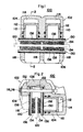
- Figures 1 to 3 show one embodiment of the disk brake device and brake pad of the invention wherein a coating layer of a zirconia based ceramics material is applied on a backing plate of a brake pad, Fig. 1 being a sectioned plan view showing the disk brake device, Fig. 2 being a sectional view taken along the line 2-2 of Fig. 1, and Fig. 3 being a perspective view showing the "brake pad;
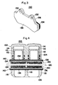
- Figures 4 to 6 show another embodiment of the disk brake device and brake pad of the present invention wherein a coating layer of a zirconia based ceramics material is applied on a backing plate of a brake pad, Fig. 4 being a sectioned plan view illustrating the disk brake device, Fig. 5 being a perspective view illustrating the brake pad, and Fig. 6 being a partly enlarged sectional view of the brake pad;
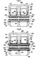
- Figure 7 is a sectioned plan view of a disk brake device showing a further embodiment of the present invention wherein coating layers of a zirconia based ceramics material are applied on an extreme end of a piston (a brake pad engaging member) and on the engaging hook (also a brake pad engaging member) of the counter-operating portion of the caliper body;
- Figure 8 is a sectioned plan view of a disk brake device showing a still further embodiment of the present invention wherein coating layers of a zirconia based ceramics material are applied on a backing plate of a brake pad, an extreme end of a piston forming a brake pad engaging member, and on an engaging hook of the counter-operating portion of the caliper body;
- Figure 9 is a perspective view of a brake pad showing a still further embodiment of the present invention wherein a coating layer of zirconia based ceramics material is applied on a portion of the backing plate of a brake pad, but not about the circumferences of the hanger pin-inserting holes of the brake pad;
- Figures 12 to 14 show a still further embodiment of the present invention wherein the face of a piston, which engages a brake pad, is closed and is provided with a coating layer of a zirconia based ceramics material, Fig. 12 being a sectioned plan view of a disk brake device showing one modification, Fig. 13 being a partly cut-away perspective view of the piston showing another modification, and Fig. 14 being a partly cut-away sectional view of the piston showing a further modification.
- a coating layer 138 of a zirconia based ceramics material is provided on the backing plate 136 of a brake pad 130 over a surface facing a piston 112.
- the disk brake device is generally shown at 100, including a caliper body 102 and a pair of brake pads 130 one disposed on each side of a brake disk 120 rotatable with a wheel (not shown).
- the caliper body 102 comprises an operating portion 104 arranged on one side of the brake disk 120, a counter-operating portion 106 arranged on the other side and a bridge portion 108 for making connection therebetween, and is supported on a bracket (not illustrated) mounted to a vehicle body for movement in the axial direction of the disk by means of a sliding pin (not illustrated) and with said bridge portion 108 being positioned over and across the brake disk 120.
- the operating portion 104 is provided with a juxtaposed arrangement of brake cylinders 110 each being open on the side of the brake disk 120. Cup-shaped pistons 112 the external ends whereof are open are disposed in brake cylinders 110, the seal between the pistons and the brake cylinders being fluid-tight whereby a hydraulic chamber 114 is defined within each cylinder.
- the brake pads 130 are both supported on the caliper body 102 for movement in the disk's axial direction by means of hanger pins 116 inserted through holes 132 formed in the pads.
- the pistons 112 which act as brake pad engaging members, are advanced by brake fluid supplied to the hydraulic chambers 114, their extreme ends urge one brake pad 130 to cause it to come into sliding contact with one side of the brake disk 120.
- the resulting reaction force causes the caliper body 102 to move in the right hand direction in Figure 2, thereby causing engaging hooks 118 of the counter-operating portion 106 (which also act as brake pad engaging members) to urge the other brake pad 130 into sliding contact with the other side of the brake disk 120. In this manner, the brake disk 120 is forcedly clamped betwen both pads 130 for braking.
- the brake pads 130 are each obtained by fixedly attaching a friction pad 134 adapted to come into sliding contact with the brake disk 120 and formed for example of a copper based sintered alloy to the front side of a metal backing plate 136 and applying a zirconia based ceramics material over the rear side of the backing plate, viz. the side facing the piston 112 or the engaging hook 118, by flame spraying to form a coating layer 138.
- the brake pads 140 have a heat-resistant undercoat 142 applied over the rear side of the backing plate 136 and the coating layer 138 is formed on the surface of the undercoat by flame spraying of said zirconia based ceramics material.
- the reasons for using the zirconia (Zr0 2 ) based ceramics material for the coating layer 138 are that it has been found that such a material is stronger in terms of thermal shock reistance than other ceramics materials, has physical properties bearing resemblance to those of a metal, and excels in heat insulation.
- a coating layer obtained by flame spraying of zirconia based ceramics material has shown a thermal shock limit temperature of 650°C, a thermal conductivity of 0.0022 cal/cm.sec °C.(0.92 J/m.s.
- a coating layer obtained by flame spraying of, e.g., alumina (A1 2 0 3 ) based ceramics material shows a thermal shock limit temperature of 300°C, a thermal conductivity of 0.0126 cal/cm.sec. °C (5.28 J/m.s.°C) and a coefficient of thermal expansion of 7 x 10 6 /°C.
- the latter is poor in thermal shock, and shows a large difference in the coefficient of thermal expansion relative to the substrate material of the piston, the metal backing plate, etc.
- the zirconia based coating layer used in the present invention is significantly more advantageous than the comparatively exemplified coating layer.
- the zirconia based ceramics material used according to the present invention is applied in the form of a powder having a particle size of 10 to 44 microns (mcm), a particularly satisfactory and uniform coating layer is obtained.
- the zirconia based coating layer thickness should be from 0.2 to 0.5 mm.
- zirconia based ceramics material it may be possible to use a zirconia (Zr0 2 ) powder alone.
- a zirconia (Zr0 2 ) powder it may be possible to use a zirconia (Zr0 2 ) powder alone.
- the use with zirconia of a sintering acid, such as yttria, or calcium or magnesium oxides improves the thermal shock resistance of the coating layer; thus the use of powdery zirconia along with 3 to 12% of yttria (Y203).
- 3 to 20% of calcium oxide (CaO) or 3 to 20% of magnesia (MgO) (percentages being by weight) provides a coating layer which is significantly improved in thermal shock resistance relative to the layers obtained using zirconia alone.
- the coating layer obtained by flame spraying of the zirconia based ceramics material has a high hardness.
- the surface roughness of the coating layer is preferably reduced to 25S or less eg. by polishing, thereby reducing the amount of wear on the disk brake device component members coming into contact therewith. (Surface roughness in S may be measured by JIS B 06 01).
- the coating layer of the zirconia based ceramics material may be white and porous, and dust or the like may easily be deposited thereon, causing in a drop of quality of the resulting product.
- titanium dioxide Ti0 2
- Ti0 2 titanium dioxide
- the titanium dioxide undergoes a chemical change with hydrogen (H 2 ), nitrogen (N 2 ) or the like in a reducing gas atmosphere during flame spraying, so that a black ceramics material coating layer is formed which ensures that any externally deposited dust, etc. has no appreciably adverse influence upon the appearance of the coating layer, so that it is of high quality and has a satisfactory radiation due to its colour tone.
- an increase in the degree of blackness may be is achieved by an increase in the concentration of hydrogen or nitrogen in the reducing gas used.
- the coating layer obtained by flame spraying of the ceramics material is porous, there is a possibility that rusting may occur between it and the mother material of the backing plate, etc., by external entering of moisture, etc.
- the coating layer is impregnated with, eg, a heat-resistant organic material (for example a material based on epoxy or silicone varnish) or a heat-resistant inorganic material (for example such as water glass) then the pores of the coating layer are closed up, thus preventing external entering of moisture and resulting in improvements in the rust-proofing effect. Closing- up of the pores makes the deposition of contaminants such as dust difficult, thus resulting in an increase in the quality of the product to be obtained.
- the heat-resistant organic or inorganic materials may be added alone or in combination.
- an undercoat 142 is applied to the backing plate 136 before the zirconia based coating layer 138 so as to increase further the adhesiveness of the coating layer 138 with respect to the substrate material.
- the rear surface of the backing plate 136 is roughened by shot blasting, followed by plasma spraying of a heat-resistant metallic material having a powder particle size of 10 to 44 mcm and a relatively low coefficient of thermal expansion such as that based on stainless steel, molybdenum or nickel- chromium capable of standing up to a temperature of, for instance, about 500°C to form the undercoat 142 having a thickness of 0.02 to 0.1 mm. That undercoat is then roughened on the surface, and the coating layer 138 is formed thereon by plasma spraying of the zirconia based ceramics material.
- the mother material is firmly bonded to the undercoat 142 of the heat-resistant metal, and the coating layer 138 of the zirconia based ceramics material is firmly bonded to the surface of that undercoat 142.
- This arrangement is much more strongly adhered than that wherein the zirconia based ceramics material is directly bonded to the mother material. Also; rusting on the mother material is prevented from occurring since any moisture, which may otherwise enter from the pores of the coating layer 138, is blocked by the undercoat 142.
- an engaging member for engagement with a brake pad 150 has applied thereon a coating layer of a zirconia based ceramics material.
- undercoats 142 made of a heat-resistant metallic material are each applied to the extreme end surfaces of pistons 160, which act as brake pad engaging members, which piston surfaces are in facing arrangement with the backing plate of one brake pad 150 and to the extreme end surfaces of engaging hooks 118 which act as brake pad engaging members in the counter-operating portion 106 of the caliper body 102, which engaging hook surfaces are in facing arrangement with the backing plate 136 of the other brake pad 150.
- coating layers 138 of a zirconia based ceramics material are coated onto the undercoated surfaces.
- backing plates 136 on both brake pads 140 are also provided with undercoats 142 and zirconia based ceramics material coating layers 138.
- the undercoat 142 and coating layer 138 are provided on the rear surface of the backing plate 136 of a brake pad 170 except on regions of the rear surface about the circumferences of the brake pad mounting means apertures, the hanger pin-inserting holes 132.
- the ceramics coating layer When the ceramics coating layer is applied over the entire rear surface of the backing plate 136, wearing, cracking or peeling-off of the coating layer is easy to occur, since, in the nonbraking state, the hanger pins strike upon the ceramics coating layer at the pin-inserting holes due to the engine and running vibrations.
- the absence of any ceramics coating layer about the circumferences of the hanger pin-inserting holes 132 makes a contribution to eliminating any influence upon the ceramics coating layer 138 secured to the backing plate 136.
- the rear surface of the backing plate 136 of a brake pad 180 is provided with, at a plurality of spaced locations, rectangular strips of undercoat 142 coated with zirconia based ceramics material coating layers 138.
- the surface of a piston in facing relation to a backing plate 136 of a brake pad 150 is closed and has applied thereon a coating layer 138 of a zirconia based ceramics material.
- a cap 194 is fitted over an open extreme end 192 of a piston 190. The cap 194 is then provided on the front face 196 with an undercoat 142 of a heat-resistant metallic material, on which a coating layer 138 of the zirconia based ceramics material is applied.
- a piston 200 is shown which is inserted into a brake cylinder with its open portion 202 being directed to the hydraulic chamber.
- An undercoat 142 is provided on the front face of the closed end surface 204 and a coating layer 138 of a zirconia based ceramics material is further provided thereon.
- a piston 210 is shown which is inserted into a brake cylinder with its open portion 212 being directed to the hydraulic chamber.
- a recess 216 is formed in the front face of the closed piston end 214, and a cap 218 formed of, e.g., a heat-resistant material having a low coefficient of thermal expansion is fixed into this recess.
- the cap is provided on its front face with an undercoat 142 on which a coating layer 138 of a zirconia based ceramics material is applied.
- pistons having their extreme ends closed results in an increase in the surface area of the piston which engages with the brake pad and in the pressure acting upon the brake pad being dispersed over a greater area.
- the coating layer 138 of the zirconia based ceramics material is shown in each of the embodiments shown in Figures 7 to 14 as being provided only indirectly on the mother material of the relevant component (brake pad, piston, piston end cap, etc) by virtue of the presence of the undercoat, the coating layer 138 of course if desired may be applied directly to the mother material.
Landscapes
- Engineering & Computer Science (AREA)
- General Engineering & Computer Science (AREA)
- Mechanical Engineering (AREA)
- Coating By Spraying Or Casting (AREA)
- Braking Arrangements (AREA)
Applications Claiming Priority (20)
| Application Number | Priority Date | Filing Date | Title |
|---|---|---|---|
| JP15478/85U | 1985-02-06 | ||
| JP1547885U JPS61131540U (de) | 1985-02-06 | 1985-02-06 | |
| JP266727/85 | 1985-11-27 | ||
| JP60266722A JPS62127524A (ja) | 1985-11-27 | 1985-11-27 | デイスクブレ−キ装置のパツド裏板 |
| JP60266724A JPS62127526A (ja) | 1985-11-27 | 1985-11-27 | デイスクブレ−キ装置 |
| JP60266727A JPS62127529A (ja) | 1985-11-27 | 1985-11-27 | デイスクブレ−キ装置 |
| JP60266726A JPS62127528A (ja) | 1985-11-27 | 1985-11-27 | デイスクブレ−キ装置 |
| JP266726/85 | 1985-11-27 | ||
| JP266723/85 | 1985-11-27 | ||
| JP60266725A JPS62127527A (ja) | 1985-11-27 | 1985-11-27 | デイスクブレ−キ装置 |
| JP60266730A JPS62127532A (ja) | 1985-11-27 | 1985-11-27 | デイスクブレ−キ装置 |
| JP266728/85 | 1985-11-27 | ||
| JP266722/85 | 1985-11-27 | ||
| JP266725/85 | 1985-11-27 | ||
| JP266724/85 | 1985-11-27 | ||
| JP60266729A JPS62127531A (ja) | 1985-11-27 | 1985-11-27 | デイスクブレ−キ装置 |
| JP60266728A JPS62127530A (ja) | 1985-11-27 | 1985-11-27 | デイスクブレ−キ装置 |
| JP26672385A JPS62127525A (ja) | 1985-11-27 | 1985-11-27 | デイスクブレ−キ装置のパツド裏板 |
| JP266730/85 | 1985-11-27 | ||
| JP266729/85 | 1985-11-27 |
Publications (2)
| Publication Number | Publication Date |
|---|---|
| EP0191597A1 true EP0191597A1 (de) | 1986-08-20 |
| EP0191597B1 EP0191597B1 (de) | 1990-01-31 |
Family
ID=27579653
Family Applications (1)
| Application Number | Title | Priority Date | Filing Date |
|---|---|---|---|
| EP19860300778 Expired EP0191597B1 (de) | 1985-02-06 | 1986-02-05 | Scheibenbremsvorrichtungen |
Country Status (2)
| Country | Link |
|---|---|
| EP (1) | EP0191597B1 (de) |
| DE (1) | DE3668675D1 (de) |
Cited By (11)
| Publication number | Priority date | Publication date | Assignee | Title |
|---|---|---|---|---|
| FR2607887A1 (fr) * | 1986-12-03 | 1988-06-10 | Perrot Bremse Gmbh Deutsche | Frein a commande hydraulique, en particulier frein a disque a etrier glissant |
| EP0503625A1 (de) * | 1991-03-15 | 1992-09-16 | Otto Kurt Stahl | Reibblock für eine Scheibenbremse |
| EP0527434A3 (en) * | 1991-08-09 | 1993-08-04 | Centro Sviluppo Materiali S.P.A. | Thermal barrier made from ceramic materials for braking devices |
| EP0612930A1 (de) * | 1993-01-22 | 1994-08-31 | Christian Stahl | Reibblock für eine Scheibenbremse mit kohlenstoffaserverstärktem Kohlenstoff als Reibwerkstoffblock |
| FR2823546A1 (fr) * | 2001-04-13 | 2002-10-18 | Bosch Gmbh Robert | Piston de frein a disque, piece d'appui pour un tel piston, et frein a disque muni de ce piston |
| WO2003064881A1 (de) * | 2002-01-31 | 2003-08-07 | Kurt Stahl | Bremsklotz für eine scheibenbremse mit unterschiedlichen reibmaterialien |
| WO2008083765A1 (de) * | 2007-01-09 | 2008-07-17 | Federal-Mogul Friction Products Gmbh | Scheibenbremsbelag mit verringerter wärmeübertragung an eine zuspanneinheit |
| WO2011147663A1 (fr) * | 2010-05-25 | 2011-12-01 | Robert Bosch Gmbh | Patin de frein a disque ameliore et frein a disque comprenant ledit patin |
| JP2014516143A (ja) * | 2011-06-09 | 2014-07-07 | ベイジンウェスト・インダストリーズ・カンパニー・リミテッド | 揺動パッド式ブレーキキャリパー |
| US8863915B2 (en) * | 2005-06-25 | 2014-10-21 | Philip Herbert Adams | Disc brake pad cushions |
| CN105131903A (zh) * | 2015-07-31 | 2015-12-09 | 安徽省中力车辆制动系统制造有限公司 | 一种少金属刹车片以及其生产工艺 |
Citations (7)
| Publication number | Priority date | Publication date | Assignee | Title |
|---|---|---|---|---|
| US3563347A (en) * | 1968-01-10 | 1971-02-16 | Teves Gmbh Alfred | Disk brake with noise-limiting brakeshoe |
| FR2398232A1 (fr) * | 1977-07-20 | 1979-02-16 | Girling Ltd | Dispositif de manchette |
| GB2021219A (en) * | 1978-05-23 | 1979-11-28 | Sumitomo Electric Industries | Disc brakes |
| GB2049484A (en) * | 1979-05-11 | 1980-12-31 | United Technologies Corp | Ceramic coating of metal substrate |
| GB2060093A (en) * | 1979-07-10 | 1981-04-29 | Akebono Brake Ind | Disc brake |
| GB2089914A (en) * | 1980-12-22 | 1982-06-30 | Brembo Spa | Disc brake; piston |
| US4373615A (en) * | 1981-01-26 | 1983-02-15 | General Motors Corporation | Laminated disc brake pad assembly |
-
1986
- 1986-02-05 DE DE8686300778T patent/DE3668675D1/de not_active Expired - Lifetime
- 1986-02-05 EP EP19860300778 patent/EP0191597B1/de not_active Expired
Patent Citations (7)
| Publication number | Priority date | Publication date | Assignee | Title |
|---|---|---|---|---|
| US3563347A (en) * | 1968-01-10 | 1971-02-16 | Teves Gmbh Alfred | Disk brake with noise-limiting brakeshoe |
| FR2398232A1 (fr) * | 1977-07-20 | 1979-02-16 | Girling Ltd | Dispositif de manchette |
| GB2021219A (en) * | 1978-05-23 | 1979-11-28 | Sumitomo Electric Industries | Disc brakes |
| GB2049484A (en) * | 1979-05-11 | 1980-12-31 | United Technologies Corp | Ceramic coating of metal substrate |
| GB2060093A (en) * | 1979-07-10 | 1981-04-29 | Akebono Brake Ind | Disc brake |
| GB2089914A (en) * | 1980-12-22 | 1982-06-30 | Brembo Spa | Disc brake; piston |
| US4373615A (en) * | 1981-01-26 | 1983-02-15 | General Motors Corporation | Laminated disc brake pad assembly |
Cited By (13)
| Publication number | Priority date | Publication date | Assignee | Title |
|---|---|---|---|---|
| FR2607887A1 (fr) * | 1986-12-03 | 1988-06-10 | Perrot Bremse Gmbh Deutsche | Frein a commande hydraulique, en particulier frein a disque a etrier glissant |
| EP0503625A1 (de) * | 1991-03-15 | 1992-09-16 | Otto Kurt Stahl | Reibblock für eine Scheibenbremse |
| EP0527434A3 (en) * | 1991-08-09 | 1993-08-04 | Centro Sviluppo Materiali S.P.A. | Thermal barrier made from ceramic materials for braking devices |
| EP0612930A1 (de) * | 1993-01-22 | 1994-08-31 | Christian Stahl | Reibblock für eine Scheibenbremse mit kohlenstoffaserverstärktem Kohlenstoff als Reibwerkstoffblock |
| FR2823546A1 (fr) * | 2001-04-13 | 2002-10-18 | Bosch Gmbh Robert | Piston de frein a disque, piece d'appui pour un tel piston, et frein a disque muni de ce piston |
| WO2003064881A1 (de) * | 2002-01-31 | 2003-08-07 | Kurt Stahl | Bremsklotz für eine scheibenbremse mit unterschiedlichen reibmaterialien |
| US8863915B2 (en) * | 2005-06-25 | 2014-10-21 | Philip Herbert Adams | Disc brake pad cushions |
| WO2008083765A1 (de) * | 2007-01-09 | 2008-07-17 | Federal-Mogul Friction Products Gmbh | Scheibenbremsbelag mit verringerter wärmeübertragung an eine zuspanneinheit |
| FR2960614A1 (fr) * | 2010-05-25 | 2011-12-02 | Bosch Gmbh Robert | Patin de frein a disque ameliore et frein a disque comprenant ledit patin |
| WO2011147663A1 (fr) * | 2010-05-25 | 2011-12-01 | Robert Bosch Gmbh | Patin de frein a disque ameliore et frein a disque comprenant ledit patin |
| JP2014516143A (ja) * | 2011-06-09 | 2014-07-07 | ベイジンウェスト・インダストリーズ・カンパニー・リミテッド | 揺動パッド式ブレーキキャリパー |
| US9416829B2 (en) | 2011-06-09 | 2016-08-16 | Beijingwest Industries Co. Ltd. | Pivot pad brake caliper |
| CN105131903A (zh) * | 2015-07-31 | 2015-12-09 | 安徽省中力车辆制动系统制造有限公司 | 一种少金属刹车片以及其生产工艺 |
Also Published As
| Publication number | Publication date |
|---|---|
| DE3668675D1 (de) | 1990-03-08 |
| EP0191597B1 (de) | 1990-01-31 |
Similar Documents
| Publication | Publication Date | Title |
|---|---|---|
| EP0191597B1 (de) | Scheibenbremsvorrichtungen | |
| JP2568899B2 (ja) | 複合ガスケット | |
| US6668984B2 (en) | Oxidation protection for carbon/carbon composite and graphite friction materials | |
| KR950031745A (ko) | 다양한 플랜지들의 조립체를 구비하는 고에너지 제동용 다재료 디스크 | |
| CA2236153A1 (en) | Coated article | |
| EP0816526A3 (de) | Isolierendes, wärmedämmendes Beschichtungssystem | |
| EP2663785A1 (de) | Bremskolben und kolbennasen | |
| EP0304176A3 (de) | Beschichteter Verbundkörper aus hochschmelzenden Metallen | |
| US8383197B2 (en) | Titanium carbide or tungsten carbide with combustion synthesis to block porosity in C-C brake discs for antioxidation protection | |
| ATE118607T1 (de) | Reibblock für eine scheibenbremse. | |
| KR100399273B1 (ko) | 촉매적용된 하드웨어 | |
| JPH0550476B2 (de) | ||
| CA2236151A1 (en) | Article having a coating | |
| CA2236150A1 (en) | Coated article | |
| JPS62127531A (ja) | デイスクブレ−キ装置 | |
| JPS62127527A (ja) | デイスクブレ−キ装置 | |
| JPH0222248B2 (de) | ||
| EP0510666B1 (de) | Hitze- und Ölbeständiges Dichtungsglied | |
| JPH0538253Y2 (de) | ||
| JPH0248769B2 (ja) | Bureekipatsudo | |
| JPS62127528A (ja) | デイスクブレ−キ装置 | |
| JPH0529384Y2 (de) | ||
| JPH0571812B2 (de) | ||
| JPH08159185A (ja) | ディスクブレーキ | |
| JPS62127529A (ja) | デイスクブレ−キ装置 |
Legal Events
| Date | Code | Title | Description |
|---|---|---|---|
| PUAI | Public reference made under article 153(3) epc to a published international application that has entered the european phase |
Free format text: ORIGINAL CODE: 0009012 |
|
| AK | Designated contracting states |
Kind code of ref document: A1 Designated state(s): DE FR GB IT |
|
| 17P | Request for examination filed |
Effective date: 19861018 |
|
| 17Q | First examination report despatched |
Effective date: 19880429 |
|
| GRAA | (expected) grant |
Free format text: ORIGINAL CODE: 0009210 |
|
| AK | Designated contracting states |
Kind code of ref document: B1 Designated state(s): DE FR GB IT |
|
| PGFP | Annual fee paid to national office [announced via postgrant information from national office to epo] |
Ref country code: FR Payment date: 19900227 Year of fee payment: 5 |
|
| PGFP | Annual fee paid to national office [announced via postgrant information from national office to epo] |
Ref country code: GB Payment date: 19900228 Year of fee payment: 5 |
|
| REF | Corresponds to: |
Ref document number: 3668675 Country of ref document: DE Date of ref document: 19900308 |
|
| ET | Fr: translation filed | ||
| ITF | It: translation for a ep patent filed | ||
| PLBE | No opposition filed within time limit |
Free format text: ORIGINAL CODE: 0009261 |
|
| STAA | Information on the status of an ep patent application or granted ep patent |
Free format text: STATUS: NO OPPOSITION FILED WITHIN TIME LIMIT |
|
| 26N | No opposition filed | ||
| PG25 | Lapsed in a contracting state [announced via postgrant information from national office to epo] |
Ref country code: GB Effective date: 19910205 |
|
| ITTA | It: last paid annual fee | ||
| GBPC | Gb: european patent ceased through non-payment of renewal fee | ||
| PG25 | Lapsed in a contracting state [announced via postgrant information from national office to epo] |
Ref country code: FR Effective date: 19911031 |
|
| REG | Reference to a national code |
Ref country code: FR Ref legal event code: ST |
|
| PGFP | Annual fee paid to national office [announced via postgrant information from national office to epo] |
Ref country code: DE Payment date: 19970214 Year of fee payment: 12 |
|
| PG25 | Lapsed in a contracting state [announced via postgrant information from national office to epo] |
Ref country code: DE Free format text: LAPSE BECAUSE OF NON-PAYMENT OF DUE FEES Effective date: 19981103 |
|
| PG25 | Lapsed in a contracting state [announced via postgrant information from national office to epo] |
Ref country code: IT Free format text: LAPSE BECAUSE OF NON-PAYMENT OF DUE FEES;WARNING: LAPSES OF ITALIAN PATENTS WITH EFFECTIVE DATE BEFORE 2007 MAY HAVE OCCURRED AT ANY TIME BEFORE 2007. THE CORRECT EFFECTIVE DATE MAY BE DIFFERENT FROM THE ONE RECORDED. Effective date: 20050205 |