EP0192855A2 - Appareil de marquage de pneumatiques - Google Patents
Appareil de marquage de pneumatiques Download PDFInfo
- Publication number
- EP0192855A2 EP0192855A2 EP85116640A EP85116640A EP0192855A2 EP 0192855 A2 EP0192855 A2 EP 0192855A2 EP 85116640 A EP85116640 A EP 85116640A EP 85116640 A EP85116640 A EP 85116640A EP 0192855 A2 EP0192855 A2 EP 0192855A2
- Authority
- EP
- European Patent Office
- Prior art keywords
- tire
- marking
- marker
- irregularity
- fluid
- Prior art date
- Legal status (The legal status is an assumption and is not a legal conclusion. Google has not performed a legal analysis and makes no representation as to the accuracy of the status listed.)
- Granted
Links
Images

Classifications
-
- G—PHYSICS
- G01—MEASURING; TESTING
- G01M—TESTING STATIC OR DYNAMIC BALANCE OF MACHINES OR STRUCTURES; TESTING OF STRUCTURES OR APPARATUS, NOT OTHERWISE PROVIDED FOR
- G01M1/00—Testing static or dynamic balance of machines or structures
- G01M1/14—Determining imbalance
- G01M1/16—Determining imbalance by oscillating or rotating the body to be tested
- G01M1/26—Determining imbalance by oscillating or rotating the body to be tested with special adaptations for marking, e.g. by drilling
-
- G—PHYSICS
- G01—MEASURING; TESTING
- G01M—TESTING STATIC OR DYNAMIC BALANCE OF MACHINES OR STRUCTURES; TESTING OF STRUCTURES OR APPARATUS, NOT OTHERWISE PROVIDED FOR
- G01M17/00—Testing of vehicles
- G01M17/007—Wheeled or endless-tracked vehicles
- G01M17/02—Tyres
- G01M17/022—Tyres the tyre co-operating with rotatable rolls
- G01M17/024—Tyres the tyre co-operating with rotatable rolls combined with tyre surface correcting or marking means
Definitions
- This invention relates to a marking device and more particularly to a marking device adapted to mark tires.
- the instant invention relates to a tire marking device used in conjunction with a tire inspection machine in order to allow the tire to be marked at the location of irregularities detected by the tire inspection means.
- the instant invention employs means for receiving a signal indicative of the location of an irregularity in the tire being inspected and subsequently causing a paint to be applied to the tire in proximity to the irregularity detected by the tire inspection machine.
- Means for marking tires are known in the art as disclosed by U.S. Patent No. 3,518,878 to Landsness, et al which discloses an apparatus for making a mark on a rotating tire at the location corresponding to the place of maximum of the fundamental frequency of the radial force variation comprising an arcuately oscillable marker mounted on a shaft having an acuator operatively connected to the shaft for rotating the marker to contact the sidewall of the tire. Rollers contacting the sidewall of the tire support the apparatus on the rotating tire.
- U.S. Patent No. 3,526,131 to Buser, et al relates to an apparatus for marking the location on a tire of the first harmonic.
- the apparatus employs a heated branding iron which is automatically dipped in wax and pressed against a tire at the location to be marked.
- the branding iron is moved to and from the tire by a pneumatic actuator cylinder, which in turn is controlled by an electronic control circuit which operates in response to force variation readings taken around the circumference of a tire by a conventional force variation measurement machine.
- the heated branding iron makes a permanent indentation on the tire and simultaneously deposits a wax ring around the indentation to make it more readily visible.
- U.S. Patent No. 3,631,716 to Monajjem relates to a marking device used to mark a rotating tire to indicate the location at which a given force variation is generated.
- a marking device used to mark a rotating tire to indicate the location at which a given force variation is generated.
- the point on the tire at which this force variation is produced passes beneath the marker at which time a solenoid is activated to abruptly move the marker toward the sidewall of the tire and to cause the marker to mark the tire with a suitable marking fluid such as ink.
- the abrupt movement of the marker causes it to eject a small amount of marking fluid and to deposit the fluid on the tire sidewall.
- the marker solenoid is operated by a relay circuit activated by a signal from the tire uniformity machine.
- U.S. Patent No. 3,911,739 to Murata, et al relates to a marking device which comprises a rotary shaft, a first disc member securely mounted on the rotary shaft and carrying a marking means; a second disc freely rotatably mounted on the rotary shaft and adapted to be brought into pressing contact with a tire surface for rotation therewith, and a mechanism for transmitting rotational movement of the second disc member to the first disc member through the rotary shaft upon receipt of a signal from the measuring device for running the marking means at a speed same as the circumferential speed of the rotating tire.
- the apparatus further includes a means for holding the marking means in a standby position.
- U.S. Patent No. 4,308,747 to Reed is directed to a tire marking device comprising a tubular housing carried by a rotatable shaft which receives a marking fluid that is dispensed at the lower end thereof by a spring-loaded ball that is depressed by contact with the tire sidewall.
- the shaft is rotated to move the ball into contact with the tire in response to the sensor sensing the radial first harmonic high point on the tire with rotation of the shaft being synchronized with movement of the tire so that the radial first harmonic high point of the tire corresponds with the point of contact with the ball with the tire.
- U.S. Patent No. 4,440,018 to Christie is directed to a tire testing machine which measures lateral runout of the tire sidewalls.
- the resulting data is converted to digital form and analyzed by groups in order to increase the accuracy by which unacceptable sidewalls are detected.
- the device employs contact type sensors to sense variations in the sidewalls of the tire.
- the apparatus also provides means for marking the tire utilizing eight separate stamping plates supplied with ink and actuated by each solenoid which are capable of depressing individual plates into contact with the tire thereby providing a means for providing 28 different patterns of marks which can be placed on the tire..
- the sidewall at the lap splice When inflated the sidewall at the lap splice may not expand to the same degree as the sidewall as a whole, thus generating a deformation commonly referred to as a depression. While this depression is an indication of exceptional strength at that point of the sidewall, the presence of the depression is considered by the consuming public to be unsightly and thus undesirable.
- the sidewalls In the case of an open splice, the sidewalls may be weakened such that when inflated the weakened area at the splice will excessively expand to cause what is commonly referred to as a bulge. Such a bulge may be an indication of a weakened area in the sidewall and may also be considered unsightly if excessive. Bulges may also be created by a reduced cord count in a localized area.
- the present invention relates to a means for marking.the actual locations on a tire sidewall where bulges or depressions occur, employing a means for spraying an ink on the tire sidewall at the location of such bulges or depressions.
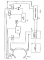
- Fig. 1 of the drawings there is disclosed a simplified schematic drawing illustrating the instant invention.
- the instant invention is adapted to be used in conjunction with a tire sidewall deformity tester such as that disclosed in U.S. Patent No. 4,258,567 to Fisher III, which patent is incorporated herein by reference.
- a tire 11 as shown in Fig. 1 of the drawings is mounted in a tire uniformity optimizer (TUO) in order to provide a means for rotating the tire about an axis to facilitate inspection of the tire.
- TOU tire uniformity optimizer
- sensors 12 mounted in proximity thereto and displaceable about the tire sidewalls are sensors 12 adapted to detect irregularities in the contour of the sidewalls of the tire.
- the sensors 12 may be of a type disclosed in U.S. Patent No. 4,258,567 or may include other types of sensors including lasers.
- the sensors 12 may be movably mounted with respect to the tire 11 to facilitate mounting of the tire 11 within the TUO 10.
- marking unit 13 which, as discussed in more detail below, is adapted to apply a marking substance to the tire sidewall.
- the marking unit 13 may also be movably mounted with respect to the tire 11 in order to facilitate mounting of the tire 11 within the TUO 10. It should be appreciated, for reasons discussed in more detail below, that the sensors 12 and the marking units 13 do not necessarily need to be mounted adjacent to each other. However, it is important that the angular displacement between the sensors 12 and marking unit 13 remain constant.
- the marking unit 13 is, in the exemplary embodiment, comprised of a model DS-10 Micro-Mini Marker produced by Del Products, 625 Wanda, Ferndale, Michigan 48220, which is a non-contact color marker employing an independent atomizing air source to provide a quick response time for the marking process.
- the marking fluid is fed to the marking unit 13 by a pressurized ink feed system.
- the marker is an atomizing spray type, and a water-based ink is employed in the exemplary embodiment.
- the marking unit 13 may selectively receive an input of an air supply from control valve 21 which selectively ports 80 psi air from air supply 19 through control valve 21 to the marking unit 13 in order to activate a cylinder within the marker which allows pressurized ink to flow through the marker orifice and thus be applied to the tire sidewall.
- the marker 13 only allows the pressurized ink to be applied to the sidewall of the tire when air pressure is supplied to the cylinder within the marker unit 13.
- a second source of air pressure from air supply 19 is through regulator 25 and valve 26, which valve may be selectively actuated to either allow or restrict air flow through valve 26 to the marking unit 13 in order to provide air flow around an air cap on the marker face which atomizes any ink flowing through the orifice of the marker unit 13.
- a circulating pump 29 that is employed to cause ink to be circulated from an ink reservoir 31 to the marker unit 13 and then returned to the reservoir 31 for further recirculation.
- the recirculation of the ink helps to prevent solid material in the ink from setting, assures that a supply of ink will always be at the marker and also automatically purges the lines of trapped air.
- the operation of the solenoid actuated valves is governed by the marker control 32 which in turn receives the inputs from the Sidewall Inspection Controller 33 . .
- a one-second timer reference is started which is used as an index of tire rotational position until after the tire is marked.
- the TUO spindle drive is comprised of an 1800 rpm synchronous motor, a 19.5 to 1 gearbox and a 40 to 26 timing pulley ratio from the gearbox to the spindle in order to provide the appropriate rotation of the tire in order that the instant invention may employ a marking means which is time based.
- the rotation of the tire is 60 revolutions per minute.
- the tire sidewall inspection system relates time to position with one second being one complete revolution of the tire.
- the tire sidewall inspection system starts both tests at the one second index positions and remembers irregularity locations by remembering the time between the one second index reference and the time that the irregularity location data was taken.
- the tire is rotated until the one second index reference has been reached. There is then a delay of a fixed amount of time to compensate for the angular displacement between the sensor 12 in the marking unit 13. There is a further delay introduced corresponding to the time difference between the index point and the time that the reject location data was taken during the test. After these two delays, the marking unit 13 is energized to cause the pressurized ink to be applied to the tire sidewall at a position which corresponds to the actual location of the irregularities detected by the tire sidewall inspection system.
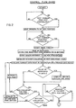
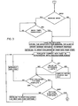
- FIG. 2 through 4 of the drawings there is disclosed a schematic block diagram showing the-sequence of operation of the instant invention.
- the flow chart begins with decision block DB1 where the .Sidewall Inspection Controller (SIC) 33 is waiting for a command from the Host Controller to test a tire. At this point, the sensors 12 are retracted. The Host Controller controls the tire testing machine which tests tires for many other variables in addition to sidewall bulges and depressions.
- a test command is received by the SIC, the SIC positions its sensors to a first sidewall test path. The SIC now waits for a start test command (DB2) from the Host Controller to commence the test. This prevents the SIC from taking data prior to the tire being fully inflated, rotating, etc.
- DB2 start test command
- the SIC After the start test command has been received, the SIC starts a software index timer which is coincident with the time for the tire to rotate one revolution. This timer will remain on until after marking is complete. After the index timer is started, the SIC takes time based data (using a second software timer) from the sensors for a given period of time which results in a given number of evenly spaced data points for each tire revolution (both top and bottom) plus a given number of overlap data points. This data is stored in memory for later analysis.
- the servo controller is now told to position the sensors 12 at the second test path position. While the sensors are being re-positioned, the first path test data in memory is evaluated . for bulges and depressions that exceed limits.
- the evaluation is sequential in nature and includes decision blocks DB3, DB4 and DB4A in the flow chart. If a bulge or depression is found that exceeds limits (DB3), its sector location is computed and saved for later marking. The data (both top and bottom of the tire) is sequentially evaluated until all data is evaluated (DB4A).
- Computation of sectors to be marked consists of taking the data point number that comprises the approximate center of the bulge or depression and dividing by a constant and truncating any remainder, e.g., if there were 1024 data points and the divisor constant were 8, there would be a possible 128 sectors, and if the data point that comprised the center of the bulge or depression were 618, the sector location for that bulge or depression would be 77.
- Sector location storage is via a memory buffer the size of which is the same as the number of possible sectors.
- the location of a buffer word is representative of a sector location and the contents of the buffer word are coded as to whether that sector has a bulge and/or depression that exceeds limits or not for purposes of selective marking.
- the second path data (both top and bottom) is evaluated for bulges and depressions that exceed limits and the sector location numbers for same computed and saved for later marking - (DB7, DB8 and DBBA) as previously described for the first path.
- DB9 is utilized to determine whether location marking is required. If no marking is required, the SIC communicates test results to the Host Controller which handles the future disposition of the tire and the SIC returns to the start of the flow chart where it is waiting for a test command from the Host Controller.
- the marker atomizing air is turned on in preparation for marking and a check is made (DBIO) for a transition of the index timer which would indicate that the tire is at the same rotational position as it was at the start of both the first and second path tests.
- DBIO DBIO
- the system would now delay for a fixed period of time to compensate for the angular mounting location differences between the SIC sensors and the marker. This allows the rotational position on the tire that was at the sensors at the start of both tests to be positioned at the marker.
- the tire rotational position at the marker is coincident with the first marking sector buffer location. Its contents are now examined in conjunction with the marking mode (mark bulges, depressions or both) to determine if this sector requires marking (DB11); if it does, the marker cylinder is air activated to allow pressurized ink to flow out of the marker which in conjunction with the atomizing air previously turned on results in atomized ink applied to the tire. The cylinder air remains on for the time duration that it takes the tire to rotate one marking sector, this is shown in the flow chart after DB11. This delay is required whether the current sector is being marked or not to allow the tire to rotate to the next sector for additional marking checks.
- the delay of one marking sector is i adequate to activate the mechanics of the marker system, but if it were not, software or hardware provisions would have to be made to accommodate an optimal activation time--this should not be a problem for one familiar with the art.
- the actual sector - delay in the exemplary embodiment is comprised of a software timer.
- the marker cylinder air is turned off and a check is made to see if all the marking sector buffers have been checked (DB12); if they have not, the loop comprising DB11 and DB12 is iterated until they are, at which time the atomizing air is turned off and test results are communicated to the Host Controller which handles the future disposition of the tire after which the SIC returns to the start of the flow chart.
Landscapes
- Physics & Mathematics (AREA)
- General Physics & Mathematics (AREA)
- Length Measuring Devices With Unspecified Measuring Means (AREA)
- Testing Of Balance (AREA)
- Tires In General (AREA)
- Tyre Moulding (AREA)
Applications Claiming Priority (2)
| Application Number | Priority Date | Filing Date | Title |
|---|---|---|---|
| US706998 | 1985-02-28 | ||
| US06/706,998 US4670289A (en) | 1985-02-28 | 1985-02-28 | Tire marker |
Publications (3)
| Publication Number | Publication Date |
|---|---|
| EP0192855A2 true EP0192855A2 (fr) | 1986-09-03 |
| EP0192855A3 EP0192855A3 (en) | 1987-08-05 |
| EP0192855B1 EP0192855B1 (fr) | 1990-10-03 |
Family
ID=24839946
Family Applications (1)
| Application Number | Title | Priority Date | Filing Date |
|---|---|---|---|
| EP85116640A Expired EP0192855B1 (fr) | 1985-02-28 | 1985-12-28 | Appareil de marquage de pneumatiques |
Country Status (5)
| Country | Link |
|---|---|
| US (1) | US4670289A (fr) |
| EP (1) | EP0192855B1 (fr) |
| JP (1) | JPS61201130A (fr) |
| DE (1) | DE3580027D1 (fr) |
| ES (1) | ES8700161A1 (fr) |
Families Citing this family (10)
| Publication number | Priority date | Publication date | Assignee | Title |
|---|---|---|---|---|
| JPH0820228B2 (ja) * | 1990-01-31 | 1996-03-04 | 住友ゴム工業株式会社 | タイヤ外周面のプロファイル測定方法及びその装置 |
| US5065694A (en) * | 1990-08-20 | 1991-11-19 | Cooper Tire And Rubber Co. | Automatic white sidewall spraying apparatus |
| US5109715A (en) * | 1991-02-19 | 1992-05-05 | Fmc Corporation | Location designator for wheel service machines |
| US5249460A (en) * | 1991-12-16 | 1993-10-05 | Bridgestone Corporation | Method and apparatus for measuring irregular tread wear |
| US5245867A (en) * | 1991-12-16 | 1993-09-21 | Bridgestone Corporation | Method and apparatus for measuring tire parameters |
| IT1289701B1 (it) * | 1996-11-29 | 1998-10-16 | Bridgestone Firestone Tech | Metodo per la marcatura di un pneumatico |
| US5840138A (en) * | 1997-04-25 | 1998-11-24 | The Goodyear Tire & Rubber Company | Waterborne radial first harmonic marking of tires |
| JPH11278020A (ja) * | 1998-03-26 | 1999-10-12 | Bridgestone Corp | マーキング検査装置 |
| US6269689B1 (en) * | 1998-07-22 | 2001-08-07 | Oliver Rubber Company | Tire inspection equipment and method |
| JP6234718B2 (ja) * | 2013-07-02 | 2017-11-22 | 株式会社神戸製鋼所 | タイヤ試験機 |
Family Cites Families (14)
| Publication number | Priority date | Publication date | Assignee | Title |
|---|---|---|---|---|
| US1700697A (en) * | 1925-10-12 | 1929-01-29 | Draper Mfg Co | Means for coating cylindrical artioles |
| GB1238189A (fr) * | 1967-07-08 | 1971-07-07 | ||
| US3500681A (en) * | 1968-08-12 | 1970-03-17 | Goodrich Co B F | Locating maximum radial force variation in a tire |
| US3526131A (en) * | 1968-09-09 | 1970-09-01 | Goodyear Tire & Rubber | Tire marking apparatus |
| US3518878A (en) * | 1968-11-25 | 1970-07-07 | Goodrich Co B F | Apparatus for marking a rotating tire |
| US3631716A (en) * | 1970-02-17 | 1972-01-04 | Gen Tire & Rubber Co | Force variation marker for tires |
| JPS5097411A (fr) * | 1973-12-28 | 1975-08-02 | ||
| GB1451562A (en) * | 1974-05-28 | 1976-10-06 | Gnii Mashinovedeniya | Method of balancing rotors and device for realisation thereof |
| US4078339A (en) * | 1974-11-18 | 1978-03-14 | Ongaro Dynamics, Inc. | Method for correcting rubber tires for forces generated by dynamic non-uniformities |
| US4308747A (en) * | 1980-03-27 | 1982-01-05 | The B. F. Goodrich Company | Apparatus for marking radial first harmonic high point on a tire |
| US4359897A (en) * | 1981-02-25 | 1982-11-23 | Uniroyal, Inc. | Apparatus for marking a rotating tire |
| DE3115609A1 (de) * | 1981-04-16 | 1982-11-04 | Gebr. Hofmann Gmbh & Co Kg Maschinenfabrik, 6100 Darmstadt | Verfahren und vorrichtung zum kennzeichnen von unwuchten an einem rotationskoerper, insbesondere kraftfahrzeugrad" |
| US4440018A (en) * | 1982-01-18 | 1984-04-03 | The Goodyear Tire & Rubber Company | Tire sidewall deformation detection techniques |
| DE3236189A1 (de) * | 1982-09-30 | 1984-04-05 | A. Rohé GmbH, 6050 Offenbach | Vorrichtung zum beruehrungslosen markieren eines rades und verfahren zum betrieb dieser vorrichtung |
-
1985
- 1985-02-28 US US06/706,998 patent/US4670289A/en not_active Expired - Fee Related
- 1985-12-28 DE DE8585116640T patent/DE3580027D1/de not_active Expired - Fee Related
- 1985-12-28 EP EP85116640A patent/EP0192855B1/fr not_active Expired
-
1986
- 1986-02-17 JP JP61031016A patent/JPS61201130A/ja active Pending
- 1986-02-26 ES ES552438A patent/ES8700161A1/es not_active Expired
Also Published As
| Publication number | Publication date |
|---|---|
| US4670289A (en) | 1987-06-02 |
| JPS61201130A (ja) | 1986-09-05 |
| ES552438A0 (es) | 1986-11-16 |
| ES8700161A1 (es) | 1986-11-16 |
| DE3580027D1 (de) | 1990-11-08 |
| EP0192855B1 (fr) | 1990-10-03 |
| EP0192855A3 (en) | 1987-08-05 |
Similar Documents
| Publication | Publication Date | Title |
|---|---|---|
| US4670289A (en) | Tire marker | |
| JP3807829B2 (ja) | クランクシャフトの自動測定装置及びその測定方法 | |
| US5033003A (en) | Wheel measuring machine | |
| US6581448B2 (en) | Snug fitting apparatus for tire assembly and manufacturing method of tire assembly | |
| US4391190A (en) | Pre-setting of printing machines | |
| HU895558D0 (en) | Process and apparatus for testing tyres | |
| EP0084514A1 (fr) | Appareil pour l'essai automatique des pneus | |
| GB2097135A (en) | Methods of and apparatus for identifying points of unbalance on rotary bodies | |
| US4440018A (en) | Tire sidewall deformation detection techniques | |
| ATE213192T1 (de) | Vorrichtung und verfahren zum korrigieren von rundlauffehlern | |
| US5267380A (en) | Method and apparatus for centering a rotary body | |
| EP1624294B1 (fr) | Vérification de l'uniformité de pneus | |
| CA1255515A (fr) | Marqueur de pneus | |
| JPH1164174A (ja) | タイヤ試験方法および装置 | |
| CA2239461A1 (fr) | Appareil de controle de pneus | |
| US2812583A (en) | Device for measuring variations in tire thickness | |
| US3911739A (en) | Apparatus for printing a mark on a rotating tire | |
| JPH10123022A (ja) | トレッドゴムの特性試験方法および特性試験装置 | |
| JP3602805B2 (ja) | タイヤ組立体の馴染み加工装置 | |
| IT1158898B (it) | Dispositivo di controllo dell'avanzamento di una mola rispetto ad un dispositivo di ravvivatura in una rettificatrice | |
| CA2261308C (fr) | Essai de resistance dynamique de mandrins de carton | |
| US3534598A (en) | Uniformity machine | |
| JPH08122220A (ja) | タイヤのユニフォーミテイ試験装置 | |
| JPH07110502B2 (ja) | 生タイヤの位置決め方法 | |
| JPH07111328B2 (ja) | 円柱状検体の直径測定装置 |
Legal Events
| Date | Code | Title | Description |
|---|---|---|---|
| PUAI | Public reference made under article 153(3) epc to a published international application that has entered the european phase |
Free format text: ORIGINAL CODE: 0009012 |
|
| AK | Designated contracting states |
Kind code of ref document: A2 Designated state(s): DE FR GB IT LU |
|
| PUAL | Search report despatched |
Free format text: ORIGINAL CODE: 0009013 |
|
| AK | Designated contracting states |
Kind code of ref document: A3 Designated state(s): DE FR GB IT LU |
|
| 17P | Request for examination filed |
Effective date: 19871109 |
|
| 17Q | First examination report despatched |
Effective date: 19880916 |
|
| GRAA | (expected) grant |
Free format text: ORIGINAL CODE: 0009210 |
|
| AK | Designated contracting states |
Kind code of ref document: B1 Designated state(s): DE FR GB IT LU |
|
| REF | Corresponds to: |
Ref document number: 3580027 Country of ref document: DE Date of ref document: 19901108 |
|
| ET | Fr: translation filed | ||
| ITF | It: translation for a ep patent filed | ||
| PGFP | Annual fee paid to national office [announced via postgrant information from national office to epo] |
Ref country code: DE Payment date: 19901221 Year of fee payment: 6 |
|
| ITTA | It: last paid annual fee | ||
| PGFP | Annual fee paid to national office [announced via postgrant information from national office to epo] |
Ref country code: GB Payment date: 19901231 Year of fee payment: 6 |
|
| PGFP | Annual fee paid to national office [announced via postgrant information from national office to epo] |
Ref country code: LU Payment date: 19910205 Year of fee payment: 6 |
|
| EPTA | Lu: last paid annual fee | ||
| PLBE | No opposition filed within time limit |
Free format text: ORIGINAL CODE: 0009261 |
|
| STAA | Information on the status of an ep patent application or granted ep patent |
Free format text: STATUS: NO OPPOSITION FILED WITHIN TIME LIMIT |
|
| 26N | No opposition filed | ||
| PG25 | Lapsed in a contracting state [announced via postgrant information from national office to epo] |
Ref country code: LU Free format text: LAPSE BECAUSE OF NON-PAYMENT OF DUE FEES Effective date: 19911228 Ref country code: GB Effective date: 19911228 |
|
| PGFP | Annual fee paid to national office [announced via postgrant information from national office to epo] |
Ref country code: FR Payment date: 19920630 Year of fee payment: 7 |
|
| GBPC | Gb: european patent ceased through non-payment of renewal fee | ||
| PG25 | Lapsed in a contracting state [announced via postgrant information from national office to epo] |
Ref country code: DE Effective date: 19920901 |
|
| PG25 | Lapsed in a contracting state [announced via postgrant information from national office to epo] |
Ref country code: FR Effective date: 19930831 |
|
| REG | Reference to a national code |
Ref country code: FR Ref legal event code: ST |