EP0193505B1 - Appareil pour le retrait et le dépôt de papiers de valeur - Google Patents
Appareil pour le retrait et le dépôt de papiers de valeur Download PDFInfo
- Publication number
- EP0193505B1 EP0193505B1 EP86850010A EP86850010A EP0193505B1 EP 0193505 B1 EP0193505 B1 EP 0193505B1 EP 86850010 A EP86850010 A EP 86850010A EP 86850010 A EP86850010 A EP 86850010A EP 0193505 B1 EP0193505 B1 EP 0193505B1
- Authority
- EP
- European Patent Office
- Prior art keywords
- arm
- vehicle
- withdrawal
- deposit
- customer
- Prior art date
- Legal status (The legal status is an assumption and is not a legal conclusion. Google has not performed a legal analysis and makes no representation as to the accuracy of the status listed.)
- Expired - Lifetime
Links
- 238000000151 deposition Methods 0.000 title description 3
- 238000003780 insertion Methods 0.000 claims description 6
- 238000000034 method Methods 0.000 claims description 3
- 230000011664 signaling Effects 0.000 claims description 3
- 230000004044 response Effects 0.000 claims description 2
- 238000001514 detection method Methods 0.000 claims 2
- 230000004913 activation Effects 0.000 claims 1
- 230000003247 decreasing effect Effects 0.000 claims 1
- 230000000694 effects Effects 0.000 claims 1
- 239000012858 resilient material Substances 0.000 claims 1
- 238000010276 construction Methods 0.000 description 2
- 230000037431 insertion Effects 0.000 description 2
- 238000012986 modification Methods 0.000 description 2
- 230000004048 modification Effects 0.000 description 2
- 230000005855 radiation Effects 0.000 description 1
- 230000031070 response to heat Effects 0.000 description 1
- 230000007723 transport mechanism Effects 0.000 description 1
Images

Classifications
-
- G—PHYSICS
- G07—CHECKING-DEVICES
- G07F—COIN-FREED OR LIKE APPARATUS
- G07F19/00—Complete banking systems; Coded card-freed arrangements adapted for dispensing or receiving monies or the like and posting such transactions to existing accounts, e.g. automatic teller machines
- G07F19/20—Automatic teller machines [ATMs]
-
- G—PHYSICS
- G07—CHECKING-DEVICES
- G07F—COIN-FREED OR LIKE APPARATUS
- G07F19/00—Complete banking systems; Coded card-freed arrangements adapted for dispensing or receiving monies or the like and posting such transactions to existing accounts, e.g. automatic teller machines
- G07F19/20—Automatic teller machines [ATMs]
- G07F19/201—Accessories of ATMs
-
- G—PHYSICS
- G07—CHECKING-DEVICES
- G07F—COIN-FREED OR LIKE APPARATUS
- G07F19/00—Complete banking systems; Coded card-freed arrangements adapted for dispensing or receiving monies or the like and posting such transactions to existing accounts, e.g. automatic teller machines
- G07F19/20—Automatic teller machines [ATMs]
- G07F19/205—Housing aspects of ATMs
Definitions
- the present invention relates to an apparatus for the withdrawal and/or the deposit of valuable papers, such as bank-notes, cheques, etc., particularly intended for use by vehicle-carried customers, hereinafter referred to as vehicular customers.
- US-A-3077243 discloses a drive-in service unit for bank tellers having a service drawer which can be slid outward toward the car and which can be raised or lowered to accommodate a person seated in a car to transfer papers or items of value toward a teller's cage.
- Withdrawal apparatus or bank-note dispensing apparatus, intended for vehicular customers are encumbered with a number of drawbacks.
- the procedures which must be carried out e.g. insertion of a bankers card, insertion of a personal code and the sum required, removal of the card and the cash and the receipt, cannot be performed in comfort whilst seated in a vehicle. These difficulties are accentuated when the vehicle is a left-hand drive vehicle and the driver is right-handed.
- Another drawback with known apparatus of this kind is that dispensing and/or deposit apparatus intended mainly for vehicular customers are positioned at such a low level as to cause discomfort when used by pedestrian customers, who must stand in front of the apparatus when making a withdrawal or a deposit.
- the object of the invention is to eliminate these drawbacks and disadvantages.
- an apparatus for the withdrawal and/or deposit of valuable papers and intended chiefly for use by vehicular customers said apparatus including an extendable arm construction which is provided at its free end with a withdrawal and/or deposit opening, button-banks and a card-insertion aperture. Outward extension of the arm is contingent on the presence of a vehicular customer in front of the apparatus.
- the extent to which the arm is extended, the height of the free end of the arm above a given horizontal level and the lateral angle of the arm relative to the vertical can be controlled in correspondence with the presence of the customer as the arm is extended, by means of a sensor arrangement provided in the free end of the arm (thermal radiation).
- the apparatus described briefly above can be placed in a fixed location at a height convenient for a standing person of average height, and, through the agency of the flexible and individually adaptable arm, can be manipulated comfortably by a vehicular customer, irrespective of where the customer stops his/her vehicle in front of the apparatus, within certain limits of course.
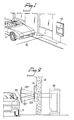
- Figure 1 illustrates an apparatus 10 intended for the withdrawal of bank-notes, i.e. a bank-note dispensing apparatus, and shows the apparatus in its inactive mode.
- the apparatus is intended for vehicular customers, i.e. customers who remain seated in their automobile when using the apparatus, and is placed at a height above ground level such that its button-banks, card-insert aperture and withdrawal opening can be reached comfortably by the driver of a vehicle 11 parked in front of the apparatus.
- the apparatus 10 may alternatively be placed at a higher level, so that it can be operated comfortably by a pedestrian customer while standing upright in front of the apparatus.
- the apparatus In addition to having button-banks, card-reader and a withdrawal opening, the apparatus also incorporates a transport mechanism effective to transport bank-notes from a storage station (20 in Figure 2) located within the apparatus, and detecting and signalling means which enable bank-notes to be fed reliably and correctly from the storage station to the withdrawal opening.
- a transport mechanism effective to transport bank-notes from a storage station (20 in Figure 2) located within the apparatus, and detecting and signalling means which enable bank-notes to be fed reliably and correctly from the storage station to the withdrawal opening.
- the apparatus 10 has a telescopically extendable arm and a further sensing or detecting means for controlling movement of the arm, and therewith its free length and the angle of the arm relative to the vertical, in dependence on the presence of a vehicular customer in front of the apparatus.
- This further detecting means comprises two units, of which one is constructed to sense the presence of a vehicle in front of the apparatus and to activate the other of said units in response thereto.
- the vehicle sensing unit is indicated in Figure 1 by a broken line and is referenced 12.
- Figure 2 illustrates the situation in which the vehicle-sensor 12 has detected the presence of the vehicle 11 in front of the apparatus 10 and has activated the aforesaid other unit (30 in Figure 3), so as to cause the arm 101 to be extended to a position in which the driver of the vehicle 11 can comfortably reach the free end of said arm.
- the apparatus is mounted in a wall 21, within which the storage station 20 (safe) is located.
- the telescopically extendable arm 101 is shown to be extended approximately horizontally, although the arm can also be raised and lowered somewhat at an angle to the horizontal, as indicated by the positions referenced 101' and 101''.
- This raising and lowering of the arm in the vertical plane is made possible by a bellow-construction 102 in the arm 101, and is controlled by the unit 30 in the detector means, in response to heat radiated from the customer.
- the bank-note dispensing apparatus 10 is placed at a height which can be reached comfortably by a vehicular passenger.
- the apparatus When the apparatus is normally intended for pedestrian customers, it may be suitably to place the apparatus on a higher level.
- the arm In the case of a pedestrian customer standing in front of the apparatus, the arm will extend to the position shown in Figure 1 and will remain in this position, while the customers makes his/her withdrawal. In the case of a vehicular customer, however, the arm will extend approximately to the position referenced 101''.
- the arm 101 is shown to be brought to a position in which it can be reached comfortably by the customer seated in the vehicle 11 (Figure 1), this customer having already inserted the amount required through the illustrated upper button-bank 32, and has proved his/her identity by inserting his/her bankers card in the card reader 33 shown to the right, and has inserted his/her personal code number through the lower button-bank 34.
- the ordered number of bank-notes 31 has been fed to the withdrawal opening 35, and is ready to be removed there-from. Removal of the bank-notes from the withdrawal opening is detected by a third detecting means, which immediately initiates and steers return movement of arm 101 to its inactive, starting position ( Figure 1).
- the detecting means 12 arranged in the road and effective to sense or detect the presence of a vehicle can be replaced with a unit having a similar function arranged on the free end of the arm 101, i.e. a unit which detects the arrival of a vehicle, and activates the unit 30 for controlling movement of the arm 101.
- the arm 101 can also be moved sideways, as shown by the arm positions referenced 101''' and 101'''.
- the further detecting means 12-30 is arranged to control extension of the arm 101, so that the arm is extended to a suitable length either perpendicularly from the wall, obliquely to the left or to the right, depending on the position of the vehicle in front of the apparatus.
- the further detecting means 12 may be constructed such that in the presence of a vehicle there is activated a start means which can be reached by a customer seated in the vehicle.
- a start means which can be reached by a customer seated in the vehicle.
- the start means is activated by the customer (e.g. a button is pressed) the arm is extended outwardly, either through a constant distance (1 in Figure 4) or to a position in which the free length of the arm and the respective angles of the arm in the horizontal and vertical planes are controlled by the presence of the customer through the detecting means (by the heat radiated from the customer).
- Guide means for steering an object towards a heat source are known per se and need not therefore be described here.
- the outer edge of the free end of the arm comprises a strip of resilient (soft) material, such as rubber, having incorporated therein a pressure-sensitive means effective to stop outward movement of the arm when meeting a mechanical obstacle (wing mirror of the vehicle or a like obstacle) during said outward movements of the arm.
- a mechanical obstacle wing mirror of the vehicle or a like obstacle
- a further modification resides in the provision of a handle on the free end of the extendable arm 101, by means of which handle the arm can be extended towards a vehicle located in front of the apparatus. Normally, the arm is latched in its inwardly inserted position, so as to prevent it from being extended by vandals and the like. This latch is only released when a passing vehicle has activated the unit 12 of the further detecting means, therewith enabling the driver of the vehicle to extend the arm and carry out his/her withdrawal. When extending the arm a spring is tensioned, which upon completion of the withdrawal (or deposit) is automatically released and therewith causes the arm to be retracted to its starting position. When this modification is incorporated, the aforedescribed further unit 30 becomes obsolete.
Landscapes
- Business, Economics & Management (AREA)
- Accounting & Taxation (AREA)
- Finance (AREA)
- Physics & Mathematics (AREA)
- General Physics & Mathematics (AREA)
- Financial Or Insurance-Related Operations Such As Payment And Settlement (AREA)
- Devices For Checking Fares Or Tickets At Control Points (AREA)
- Handcart (AREA)
Claims (11)
- Appareil destiné au retrait et/ou au dépôt de papiers de valeur, tels que des billets de banque, des chèques et autres documents semblables, et destinés en particulier à des utilisateurs de véhicules, ledit appareil comportant une ouverture (35) de retrait et/ou de dépôt accessible par l'utilisateur ; des moyens de transfert ayant pour objet de transporter les papiers de valeur entre un espace de magasin et l'ouverture de retrait et/ou de dépôt, ainsi que des groupes de touches (32,34) nécessaires, un lecteur de cartes (33) et des moyens de détection et de signalisation pour lancer le transfert des papiers de valeur en direction et en provenance de l'ouverture (35) de retrait et/ou de dépôt, caractérisé en ce que l'ouverture (35) de retrait et/ou de dépôt, les groupes de touches (32,34), une ouverture d'introduction des cartes (33), ainsi que des portions des moyens de transfert sont agencés en liaison avec un bras extensible (101) qui peut être levé et abaissé sous un certain angle par rapport à l'horizontale et déplacé latéralement vers le chauffeur d'un véhicule.
- Appareil selon la revendication 1, caractérisé en ce que le bras extensible (101) est agencé pour être étendu en direction d'un véhicule en fonction de la présence du véhicule devant l'appareil.
- Appareil selon la revendication 2, caractérisé en ce qu'en plus de l'ouverture (35) de retrait et/ou de dépôt, des groupes de touches (32,34) et de l'ouverture d'introduction des cartes (33), l'extrémité libre du bras extensible (101) est également équipée d'un autre moyen de détection (30) agencé pour contrôler l'extension du bras (101) en longueur, en hauteur et en direction latérale en fonction d'un utilisateur se trouvant à l'avant de l'appareil.
- Appareil selon la revendication 3, caractérisé en ce que l'autre moyen détecteur (12,30) comporte deux unités, dont la première (12) est par construction destinée à détecter la présence d'un véhicule devant l'appareil et à actionner l'autre unité (30) quand cette présence est détectée ; et en ce que l'autre unité (30) est agencée lorsqu'elle est activée, pour effectuer la commande du mouvement vers l'extérieur du bras (101) en fonction de l'utilisateur assis dans le véhicule détecté.
- Appareil selon l'une quelconque des revendications 2 à 4, caractérisé en ce qu'un troisième moyen de détection est agencé pour détecter la fin d'une procédure de retrait ou de dépôt, et pour faire rentrer le bras (101) jusqu'à sa position de départ immédiatement après détection d'une procédure achevée.
- Appareil selon la revendication 2, caractérisé par un second moyen détecteur (12) pour détecter la présence d'un véhicule devant l'appareil et l'activation d'un moyen de démarrage en réponse à la détection dudit véhicule, ledit moyen de démarrage étant accessible à l'utilisateur assis dans le véhicule détecté, l'extrémité libre du bras comportant autour de son arête extérieure une bande de matériau élastique (caoutchouc) dans laquelle est incorporé un moyen sensible à la pression ayant pour fonction d'arrêter le mouvement du bras vers l'extérieur lorsqu'il rencontre un objet mécanique.
- Appareil selon la revendication 1, caractérisé en ce que le bras extensible (101) est équipé à son extrémité libre d'une poignée au moyen de laquelle le bras (101) peut être tiré en direction d'un véhicule placé devant l'appareil.
- Appareil selon la revendication 7, caractérisé en ce que l'extrémité libre du bras extensible (101) est équipé, en plus de l'ouverture (35) de retrait et/ou de dépôt, des groupes de touches (30,34) et de l'ouverture d'introduction des cartes (33) mentionnés ci-dessus, d'un autre moyen de détection (12) agencé pour libérer le bras, qui est normalement verrouillé dans sa position rentrée, afin de permettre au bras d'être tiré au moyen de la poignée.
- Appareil selon l'une des revendications 7 ou 8, caractérisé en ce qu'il comprend un moyen (par exemple un ressort) pour rentrer automatiquement le bras (101) à la fin du retrait et/ou du dépôt des papiers de valeur de l'appareil ou dans l'appareil.
- Appareil selon l'une quelconque des revendications 1 à 9, caractérisé en ce qu'il comprend un verrou de sécurité qui, lorsque le bras (101) est soumis à une pression supérieure à une valeur prédéterminée, est dégagé et dégage en même temps le bras, pour lui permettre de se déplacer dans la direction parcourue par le véhicule devant l'appareil, en réduisant ou en éliminant ainsi le risque de dégradation du bras ou du véhicule pour le cas où le véhicule s'éloignerait avant que le bras n'ait été rentré.
- Appareil selon l'une quelconque des revendications 1 à 9, caractérisé en ce que le bras extensible est un bras télescopique.
Applications Claiming Priority (2)
| Application Number | Priority Date | Filing Date | Title |
|---|---|---|---|
| SE8500910A SE445863B (sv) | 1985-02-25 | 1985-02-25 | Anordning avsedd for uttag och/eller inmatning av verdepapper |
| SE8500910 | 1985-02-25 |
Publications (3)
| Publication Number | Publication Date |
|---|---|
| EP0193505A2 EP0193505A2 (fr) | 1986-09-03 |
| EP0193505A3 EP0193505A3 (en) | 1988-02-24 |
| EP0193505B1 true EP0193505B1 (fr) | 1991-08-28 |
Family
ID=20359256
Family Applications (1)
| Application Number | Title | Priority Date | Filing Date |
|---|---|---|---|
| EP86850010A Expired - Lifetime EP0193505B1 (fr) | 1985-02-25 | 1986-01-17 | Appareil pour le retrait et le dépôt de papiers de valeur |
Country Status (4)
| Country | Link |
|---|---|
| EP (1) | EP0193505B1 (fr) |
| JP (1) | JPH0693277B2 (fr) |
| DE (1) | DE3681049D1 (fr) |
| SE (1) | SE445863B (fr) |
Families Citing this family (10)
| Publication number | Priority date | Publication date | Assignee | Title |
|---|---|---|---|---|
| GB2193251B (en) * | 1986-07-31 | 1991-01-02 | Anthony Kenyon | A dispensing or receiving machine |
| JPH0387991A (ja) * | 1989-08-30 | 1991-04-12 | Koufu Nippon Denki Kk | 遠隔操作型自動現金処理機 |
| US5217088A (en) * | 1991-09-30 | 1993-06-08 | Dallman Ernest R | Satellite banking unit for drive-through bank |
| EP0661676A1 (fr) * | 1993-12-24 | 1995-07-05 | AT&T GLOBAL INFORMATION SOLUTIONS INTERNATIONAL INC. | Guichet de banque automatique |
| GB9909405D0 (en) * | 1999-04-24 | 1999-06-23 | Ncr Int Inc | Self service terminals |
| FR2803072B1 (fr) * | 1999-12-23 | 2004-09-17 | Auchan | Borne d'echange pour automobiliste a accessibilite amelioree |
| FR2890473B1 (fr) * | 2005-09-07 | 2007-11-30 | Autoroutes Du Sud De La France | Bouche de peage et borne de peage associee. |
| US20130297066A1 (en) * | 2010-11-30 | 2013-11-07 | Pheonix Gruppen | Product Provisioning System |
| JP5609662B2 (ja) * | 2011-01-18 | 2014-10-22 | 株式会社ダイフク | 洗車機 |
| EP3239934A1 (fr) * | 2016-04-26 | 2017-11-01 | Skidata Ag | Borne de stationnement et procede de fonctionnement d'une borne de stationnement |
Citations (2)
| Publication number | Priority date | Publication date | Assignee | Title |
|---|---|---|---|---|
| EP0084916A1 (fr) * | 1982-01-21 | 1983-08-03 | Staat der Nederlanden (Staatsbedrijf der Posterijen, Telegrafie en Telefonie) | Dispositif de tunnel de transfert protecteur |
| WO1986006856A1 (fr) * | 1985-05-14 | 1986-11-20 | Anthony Kenyon | Appareil de distribution automatique et appareil de depot automatique pour guichets-autos |
Family Cites Families (11)
| Publication number | Priority date | Publication date | Assignee | Title |
|---|---|---|---|---|
| US2730053A (en) * | 1952-06-11 | 1956-01-10 | Duplex Electric Company Inc | Motorized drive-in teller's window |
| US2914244A (en) * | 1958-01-10 | 1959-11-24 | James E Wheeler | Depository drawer |
| US3077243A (en) * | 1959-11-17 | 1963-02-12 | Diebold Inc | Drive-in service unit for bank tellers having a service drawer adjustable as to height |
| US3237853A (en) * | 1963-10-14 | 1966-03-01 | Diebold Inc | Deal drawer construction for bank drive-up windows |
| SE7513557L (fr) * | 1975-12-02 | 1977-06-03 | ||
| DE2814741A1 (de) * | 1978-04-05 | 1980-01-24 | Linde Ag | Pedalsteuerung fuer ein stufenlos einstellbares getriebe eines fahrzeuges |
| US4190044A (en) * | 1978-08-16 | 1980-02-26 | Wood Eugene W | Telescoping intermedullary pin |
| SE8104036L (sv) * | 1981-06-29 | 1982-12-30 | Leif Lundblad | Automat for verdepapper och andra dokument sasom sedlar, checker, kvitton, allegat mm |
| SE8201781L (sv) * | 1982-03-19 | 1983-09-20 | Leif Lundblad | For veggmontage avsedd anordning for utmatning och/eller inmatning av verdepapper |
| JPS5980879U (ja) * | 1982-11-24 | 1984-05-31 | オムロン株式会社 | 自動車用現金取扱装置 |
| JPS59112383A (ja) * | 1982-12-18 | 1984-06-28 | オムロン株式会社 | 取引処理装置 |
-
1985
- 1985-02-25 SE SE8500910A patent/SE445863B/sv unknown
-
1986
- 1986-01-17 EP EP86850010A patent/EP0193505B1/fr not_active Expired - Lifetime
- 1986-01-17 DE DE8686850010T patent/DE3681049D1/de not_active Expired - Lifetime
- 1986-02-21 JP JP3815286A patent/JPH0693277B2/ja not_active Expired - Lifetime
Patent Citations (2)
| Publication number | Priority date | Publication date | Assignee | Title |
|---|---|---|---|---|
| EP0084916A1 (fr) * | 1982-01-21 | 1983-08-03 | Staat der Nederlanden (Staatsbedrijf der Posterijen, Telegrafie en Telefonie) | Dispositif de tunnel de transfert protecteur |
| WO1986006856A1 (fr) * | 1985-05-14 | 1986-11-20 | Anthony Kenyon | Appareil de distribution automatique et appareil de depot automatique pour guichets-autos |
Also Published As
| Publication number | Publication date |
|---|---|
| SE445863B (sv) | 1986-07-21 |
| JPH0693277B2 (ja) | 1994-11-16 |
| EP0193505A3 (en) | 1988-02-24 |
| DE3681049D1 (de) | 1991-10-02 |
| EP0193505A2 (fr) | 1986-09-03 |
| JPS61240392A (ja) | 1986-10-25 |
| SE8500910D0 (sv) | 1985-02-25 |
Similar Documents
| Publication | Publication Date | Title |
|---|---|---|
| US4735289A (en) | Dispensing apparatus and deposit apparatus for drive up machines | |
| EP0193505A2 (fr) | Appareil pour le retrait et le dépôt de papiers de valeur | |
| US5644119A (en) | Customer interface for driver | |
| US20010025881A1 (en) | Self-service terminal | |
| WO2012072708A1 (fr) | Interface utilisateur pour un système de commande de produits | |
| US4798942A (en) | Easy access ticket transport mechanism | |
| KR20040002778A (ko) | 자동차의 짐칸 보호 시스템 | |
| GB2108745A (en) | Trolley control system | |
| KR101731042B1 (ko) | 스마트 전동형 핸드카 | |
| KR101731953B1 (ko) | 운전자 보호 격벽 | |
| US20120067946A1 (en) | Telescoping/Retractable Automated Transaction Module | |
| CN207586959U (zh) | 自动发卡装置 | |
| US7035822B1 (en) | Self-service terminal | |
| GB2272235A (en) | Vehicle parking system | |
| CN217655551U (zh) | 一种公路缴费装置 | |
| WO1988001083A1 (fr) | Machine automatique de distribution et de depot | |
| CN207731278U (zh) | 非接触式读卡装置及自助金融设备 | |
| JPH07249136A (ja) | 取引処理装置および駐車券処理装置 | |
| JP7184589B2 (ja) | 用紙排出機構 | |
| CN109191621B (zh) | 智能物联网门禁 | |
| CN218291717U (zh) | 一种防冲撞的门禁装置 | |
| US12073695B1 (en) | Self-sanitizing payment assembly for drive-through windows | |
| JPH07306961A (ja) | 自動料金収受装置 | |
| CN112884999A (zh) | 一种自助atm取款间危险目标检测方法 | |
| JPS59112383A (ja) | 取引処理装置 |
Legal Events
| Date | Code | Title | Description |
|---|---|---|---|
| PUAI | Public reference made under article 153(3) epc to a published international application that has entered the european phase |
Free format text: ORIGINAL CODE: 0009012 |
|
| AK | Designated contracting states |
Kind code of ref document: A2 Designated state(s): CH DE FR GB IT LI NL |
|
| PUAL | Search report despatched |
Free format text: ORIGINAL CODE: 0009013 |
|
| AK | Designated contracting states |
Kind code of ref document: A3 Designated state(s): CH DE FR GB IT LI NL |
|
| 17P | Request for examination filed |
Effective date: 19880315 |
|
| 17Q | First examination report despatched |
Effective date: 19900921 |
|
| GRAA | (expected) grant |
Free format text: ORIGINAL CODE: 0009210 |
|
| AK | Designated contracting states |
Kind code of ref document: B1 Designated state(s): CH DE FR GB IT LI NL |
|
| PG25 | Lapsed in a contracting state [announced via postgrant information from national office to epo] |
Ref country code: NL Effective date: 19910828 Ref country code: LI Effective date: 19910828 Ref country code: CH Effective date: 19910828 |
|
| REF | Corresponds to: |
Ref document number: 3681049 Country of ref document: DE Date of ref document: 19911002 |
|
| ITF | It: translation for a ep patent filed | ||
| REG | Reference to a national code |
Ref country code: CH Ref legal event code: PL |
|
| EN | Fr: translation not filed | ||
| PG25 | Lapsed in a contracting state [announced via postgrant information from national office to epo] |
Ref country code: FR Effective date: 19920117 |
|
| NLV1 | Nl: lapsed or annulled due to failure to fulfill the requirements of art. 29p and 29m of the patents act | ||
| PLBE | No opposition filed within time limit |
Free format text: ORIGINAL CODE: 0009261 |
|
| STAA | Information on the status of an ep patent application or granted ep patent |
Free format text: STATUS: NO OPPOSITION FILED WITHIN TIME LIMIT |
|
| 26N | No opposition filed | ||
| REG | Reference to a national code |
Ref country code: FR Ref legal event code: ST |
|
| PGFP | Annual fee paid to national office [announced via postgrant information from national office to epo] |
Ref country code: GB Payment date: 19950109 Year of fee payment: 10 |
|
| PGFP | Annual fee paid to national office [announced via postgrant information from national office to epo] |
Ref country code: DE Payment date: 19950127 Year of fee payment: 10 |
|
| PG25 | Lapsed in a contracting state [announced via postgrant information from national office to epo] |
Ref country code: GB Effective date: 19960117 |
|
| GBPC | Gb: european patent ceased through non-payment of renewal fee |
Effective date: 19960117 |
|
| PG25 | Lapsed in a contracting state [announced via postgrant information from national office to epo] |
Ref country code: DE Effective date: 19961001 |
|
| PG25 | Lapsed in a contracting state [announced via postgrant information from national office to epo] |
Ref country code: IT Free format text: LAPSE BECAUSE OF NON-PAYMENT OF DUE FEES;WARNING: LAPSES OF ITALIAN PATENTS WITH EFFECTIVE DATE BEFORE 2007 MAY HAVE OCCURRED AT ANY TIME BEFORE 2007. THE CORRECT EFFECTIVE DATE MAY BE DIFFERENT FROM THE ONE RECORDED. Effective date: 20050117 |