EP0194636A2 - Appareil de ventilation - Google Patents
Appareil de ventilation Download PDFInfo
- Publication number
- EP0194636A2 EP0194636A2 EP86103197A EP86103197A EP0194636A2 EP 0194636 A2 EP0194636 A2 EP 0194636A2 EP 86103197 A EP86103197 A EP 86103197A EP 86103197 A EP86103197 A EP 86103197A EP 0194636 A2 EP0194636 A2 EP 0194636A2
- Authority
- EP
- European Patent Office
- Prior art keywords
- shell
- housing
- interior
- shells
- suction
- Prior art date
- Legal status (The legal status is an assumption and is not a legal conclusion. Google has not performed a legal analysis and makes no representation as to the accuracy of the status listed.)
- Granted
Links
- 238000009423 ventilation Methods 0.000 claims abstract description 16
- 238000010438 heat treatment Methods 0.000 claims abstract description 13
- 238000009434 installation Methods 0.000 claims abstract description 8
- 238000005485 electric heating Methods 0.000 claims abstract description 5
- 238000005192 partition Methods 0.000 claims abstract description 5
- 238000003780 insertion Methods 0.000 claims abstract description 4
- 230000037431 insertion Effects 0.000 claims abstract description 4
- 230000004308 accommodation Effects 0.000 claims abstract 2
- 229920006255 plastic film Polymers 0.000 claims description 7
- 239000011888 foil Substances 0.000 claims description 6
- 239000002985 plastic film Substances 0.000 claims description 5
- 239000011810 insulating material Substances 0.000 claims description 4
- 239000002184 metal Substances 0.000 claims description 4
- 239000002991 molded plastic Substances 0.000 claims description 3
- 239000004033 plastic Substances 0.000 claims description 3
- 229920003023 plastic Polymers 0.000 claims description 3
- 229920001169 thermoplastic Polymers 0.000 claims description 3
- 230000002787 reinforcement Effects 0.000 claims description 2
- 239000004416 thermosoftening plastic Substances 0.000 claims description 2
- 229920002457 flexible plastic Polymers 0.000 claims 1
- 230000002093 peripheral effect Effects 0.000 claims 1
- 239000002984 plastic foam Substances 0.000 claims 1
- XLYOFNOQVPJJNP-UHFFFAOYSA-N water Substances O XLYOFNOQVPJJNP-UHFFFAOYSA-N 0.000 description 11
- 238000013461 design Methods 0.000 description 6
- 229920005830 Polyurethane Foam Polymers 0.000 description 4
- 238000012423 maintenance Methods 0.000 description 3
- 238000004519 manufacturing process Methods 0.000 description 3
- 238000010521 absorption reaction Methods 0.000 description 2
- 230000015572 biosynthetic process Effects 0.000 description 2
- 238000011161 development Methods 0.000 description 2
- 230000018109 developmental process Effects 0.000 description 2
- 238000000605 extraction Methods 0.000 description 2
- 238000012549 training Methods 0.000 description 2
- 238000004378 air conditioning Methods 0.000 description 1
- 230000000712 assembly Effects 0.000 description 1
- 238000000429 assembly Methods 0.000 description 1
- 230000007797 corrosion Effects 0.000 description 1
- 238000005260 corrosion Methods 0.000 description 1
- 230000000694 effects Effects 0.000 description 1
- 238000001704 evaporation Methods 0.000 description 1
- 230000008020 evaporation Effects 0.000 description 1
- 230000002349 favourable effect Effects 0.000 description 1
- 238000000227 grinding Methods 0.000 description 1
- 239000007788 liquid Substances 0.000 description 1
- 238000010422 painting Methods 0.000 description 1
- 239000011496 polyurethane foam Substances 0.000 description 1
- 238000012805 post-processing Methods 0.000 description 1
- 230000001105 regulatory effect Effects 0.000 description 1
- 238000007493 shaping process Methods 0.000 description 1
- 125000006850 spacer group Chemical group 0.000 description 1
- 239000007921 spray Substances 0.000 description 1
- 238000013022 venting Methods 0.000 description 1
- 238000009692 water atomization Methods 0.000 description 1
Images



Classifications
-
- F—MECHANICAL ENGINEERING; LIGHTING; HEATING; WEAPONS; BLASTING
- F24—HEATING; RANGES; VENTILATING
- F24H—FLUID HEATERS, e.g. WATER OR AIR HEATERS, HAVING HEAT-GENERATING MEANS, e.g. HEAT PUMPS, IN GENERAL
- F24H3/00—Air heaters
- F24H3/02—Air heaters with forced circulation
- F24H3/04—Air heaters with forced circulation the air being in direct contact with the heating medium, e.g. electric heating element
- F24H3/0405—Air heaters with forced circulation the air being in direct contact with the heating medium, e.g. electric heating element using electric energy supply, e.g. the heating medium being a resistive element; Heating by direct contact, i.e. with resistive elements, electrodes and fins being bonded together without additional element in-between
-
- F—MECHANICAL ENGINEERING; LIGHTING; HEATING; WEAPONS; BLASTING
- F24—HEATING; RANGES; VENTILATING
- F24D—DOMESTIC- OR SPACE-HEATING SYSTEMS, e.g. CENTRAL HEATING SYSTEMS; DOMESTIC HOT-WATER SUPPLY SYSTEMS; ELEMENTS OR COMPONENTS THEREFOR
- F24D5/00—Hot-air central heating systems; Exhaust gas central heating systems
-
- F—MECHANICAL ENGINEERING; LIGHTING; HEATING; WEAPONS; BLASTING
- F24—HEATING; RANGES; VENTILATING
- F24F—AIR-CONDITIONING; AIR-HUMIDIFICATION; VENTILATION; USE OF AIR CURRENTS FOR SCREENING
- F24F13/00—Details common to, or for air-conditioning, air-humidification, ventilation or use of air currents for screening
- F24F13/20—Casings or covers
-
- F—MECHANICAL ENGINEERING; LIGHTING; HEATING; WEAPONS; BLASTING
- F24—HEATING; RANGES; VENTILATING
- F24F—AIR-CONDITIONING; AIR-HUMIDIFICATION; VENTILATION; USE OF AIR CURRENTS FOR SCREENING
- F24F6/00—Air-humidification, e.g. cooling by humidification
Definitions
- the invention relates to a ventilation device for living rooms in particular according to the preamble of the main claim.
- Ventilation devices are generally known and in use, which are generally devices which, either for ventilating or venting a room, are arranged in a wall opening or in a room window. As a rule, these are devices with the simplest type of axial blower in order to be able to manufacture and offer such devices at reasonable costs. Such simple devices are not suitable as central ventilation devices with which, for example, two or more rooms can be ventilated or a room which is located away from the installation location of the fan.
- the device defined in the preamble of the main claim is less a ventilation device, but rather a device with which the previously usual room heating systems are to be replaced, which makes it necessary to accommodate a sufficiently large heat exchanger in the housing of the device, which together with the fan takes up by far the largest part of the central interior area, around which area a U-shaped air duct is arranged in order to be able to connect air lines on all four sides of the flat, box-shaped housing, for which purpose the housing is provided with corresponding connection openings.
- the pressure-side air distribution in the housing is unfavorable and special connection pieces have to be arranged at the housing openings for the connection of the air lines.
- the invention is therefore based on the object to provide a central ventilation unit that involves simple and inexpensive manufacture and installation
- Multiple hose connection options and flow-optimized through-flow capability should be designed to be maintenance-friendly and should have sufficient interior space, in order, if desired, to be able to accommodate further additional units for air conditioning.
- such a device with a housing size of, for example, only approx. 500 L x 300 W x 20 ⁇ H mm comes with two blow-out openings provided and for the power consumption of the electric heating element, for example, only 750 watts are sufficient, since this means that If necessary, only a certain preheating of the fresh air, but no room heating should be operated. Due to the small housing dimensions, it is easily possible to install the device in the hallway between a suspended ceiling and the actual ceiling without taking up a lot of space and to guide the air ducts to be ventilated to the ventilation rooms above the suspended ceiling. Essential for easy manufacture. Installation and maintenance is that the hose connection piece is already integrated into the shell ..
- the design of the housing shells according to claim 4 is preferred because such training compared to training from PU foam, which would of course also be possible, and is provided for the known and aforementioned heating and ventilation device, is much cheaper and the shells designed in this way do not require any post-processing (grinding) and painting, which is necessary with PU foam if the whole is to have an appealing external appearance.
- a correspondingly large water pan or water bowl can either be used or molded into the lower bowl, or this space, which lends itself to the blower anyway, can be used directly as a water pan, which in detail will be explained later.
- a water atomization device can also be installed in this area. It is also possible to accommodate an additional heating element.
- the built-in units are preferably mounted or fastened to the shell that is designed to be fastened to the wall or ceiling, the entire device is also very easy to maintain, since with the device installed on the ceiling, the lower shell can simply be removed and thus all Aggregates are directly accessible.
- the special design of the hose connection piece and with regard to the interchangeability of the filter are particularly advantageous, since the connected hose lines can remain in the connected position on the other shell even when the lower shell is removed, which is also explained in more detail.
- the ventilation device is explained in more detail below with the aid of exemplary embodiments.
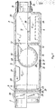
- an intake port 3 and two outlet ports 4 are arranged on opposite surfaces of the housing, integrated into the shells, which are usually also sufficient, especially since there is the possibility of branches in the outgoing hose lines if necessary to arrange.
- an air filter 8, an electric heating element 9 and the fan 10 or the fan are arranged in series between the intake and exhaust ports 3, 4 in front of a partition wall 12 which closes off an air blow-out space 11 against the interior 7.
- the partition 12 is of course provided with a corresponding opening 12 'for the blow-out opening of the fan or the fan 10.
- a thermal sensor 13 is provided which, if necessary, automatically switches on the electric heating element 9 at a correspondingly low outside temperature, and a manual switch can also be provided for switching it on.
- a limit switch is expediently provided at a suitable point for the heating element 9, which ensures that when the device is opened either with the lower one to be removed Shell 6 or when the filter closure lid 37 is opened, the heating element is switched off.
- the housing 2 With a view to a space-saving installation, the housing 2, as can also be seen in FIG. 1, has a flat, cuboid shape and the suction nozzle 3 and the two outlet nozzles 4 are arranged in the smallest areas 1 ′ of the housing 2.
- the blower 10 is advantageously one with a drum rotor 15 and suction openings 16 axially on both sides, the blower with its rotor axis 17 being arranged transversely to the flow direction in the housing 2.
- the housing 2 or its shells 5, 6 are made of plastic, such as polyurethane foam or, for the reasons mentioned, more advantageously made of heat-deformable, correspondingly thick plastic films, the two shells 5, 6 are provided with the molded-on, each half intake and exhaust ports 3 ', 4'. Since the foamable plastic itself has a sound-absorbing effect, it is advantageously possible to dispense with an additional arrangement of sound-insulating material in such a configuration. In the preferred embodiment made of synthetic foils (two foils 31, 32 each form a shell), the resulting cavity 33 can be filled with suitable insulating material, possibly even from preformed molded parts. Reinforcements 30 (FIG.
- the shell 5 can be included in the shell 5 to be fastened to the ceiling and supporting the units, in order to be able to provide a simple and durable ceiling or wall connection.
- the inner foil 32 has to be provided with the shape-specific wall designs for the interior 7.
- FIG. 6 The possibility of installing such a ventilation device is illustrated in FIG. 6, for example, from which it can be seen that that the intake manifold with an intake line 21 communicates with the outside air, while on the pressure side of the exhaust pipe 4 distribution lines 20 are guided to the ventilating rooms.
- This device installation and cable routing are carried out, for example, hidden between a ceiling suspended in the hallway and the actual hallway ceiling.
- flow regulating flaps 19 or opening closure flaps 20 can also be provided for the individual outlet ports 4. This makes it possible to either ventilate all the rooms that can be filled at the same time or alternatively.
- the wet rooms namely the kitchen, bathroom and possibly toilet, can be vented, as shown, with simple ventilation devices 23 installed directly in the outer wall, but it is also possible to use the ventilation device described according to FIG. 5 with a separate interior space 7 '. to be provided and to arrange a space extraction fan 10 'acting in the opposite direction in this. Corresponding suction lines and a blow-out line then lead from the wet rooms to the outside via the separate interior space 7 '.
- the additional effort that arises for the formation of such a device is in any case unrelated to the additional effort that would be given by the separate arrangement of respective individual room ventilators 23.
- the intake and exhaust ports 3, 4 are each formed half as integral parts of the shells 5, 6, with half the parts of the intake and exhaust ports 3, 4 of one shell being dimensioned longer than that in view of favorable maintenance the other shell.
- This makes it possible to remove the entire lower part or the lower shell 6 without having to detach the air hoses from the upper shell 5.
- the air hoses 34 are inserted into the nozzle halves and a hose clamp 35 holds the hose 34 without including the lower, shorter nozzle half 4 '.
- the shell closures 36 FIG. 7 have to be released.
- the blower housing also to be molded at the same time, this housing then of course also being divided in half. From the same point of view, at least the upper shell 6 and at least for the air filter 8 insert webs 29 can be integrally formed with it, so that the filter 8 with the simplest assembly need only be inserted through the insertion slot 38 and can also be easily replaced without that the two shells have to be opened. j
- a suitable seal is inserted along the suitably shaped shell edges 18 and the two shells are fixed against one another with suitable closure elements 36. Due to the described ease of removal of the lower shell 6, the upper shell can easily be fixed from the inside by screwing, for which purpose the upper shell is provided with corresponding through openings 39 for the fastening screws. Special and, for example, laterally protruding connection projections for the attachment of such fasteners are unnecessary.
- the embodiment according to FIG. 9 is particularly easy to implement, since it uses a flat, sufficiently strong plate 36, for example made of suitable sheet metal, and this with a thermoplastic deformable, likewise sufficiently thick plastic film 32 forming the interior contour of the housing 2 to form a shell 5 or 6 is combined, so that all necessary and essential deformations are concentrated on the easily deformable plastic film 32, which then forms the "inner skin" to a certain extent in the housing 2.
- edges 36 'of the plate 36 are folded over and the edges 32' of the molded plastic film are arranged pushed into the folded edges 36 '.
- This is expediently carried out in such a way that first three edges 36 'of the plate 36 are folded over, then the molded plastic film with its edges 32' is pushed into the folded edges 36 'and then the open edge 36' is also folded over or closed.
- Such a shell can of course be easily provided at locations where the sheet metal plate and the plastic film lie flat against one another with brackets in order to attach the relevant shell itself to a wall or ceiling and / or to provide brackets for the assemblies of the type mentioned above .
- a filling of the cavities between the sheet metal plate and the shaped film with a suitable insulating material is of course no problem in this embodiment either.
Landscapes
- Engineering & Computer Science (AREA)
- Chemical & Material Sciences (AREA)
- Combustion & Propulsion (AREA)
- Mechanical Engineering (AREA)
- General Engineering & Computer Science (AREA)
- Physics & Mathematics (AREA)
- Thermal Sciences (AREA)
- Ventilation (AREA)
- Massaging Devices (AREA)
- Seal Device For Vehicle (AREA)
- Iron Core Of Rotating Electric Machines (AREA)
- Central Heating Systems (AREA)
Priority Applications (1)
| Application Number | Priority Date | Filing Date | Title |
|---|---|---|---|
| AT86103197T ATE44312T1 (de) | 1985-03-13 | 1986-03-10 | Lueftungsgeraet. |
Applications Claiming Priority (2)
| Application Number | Priority Date | Filing Date | Title |
|---|---|---|---|
| DE8507233U | 1985-03-13 | ||
| DE8507233U DE8507233U1 (de) | 1985-03-13 | 1985-03-13 | Lüftungsgerät |
Publications (3)
| Publication Number | Publication Date |
|---|---|
| EP0194636A2 true EP0194636A2 (fr) | 1986-09-17 |
| EP0194636A3 EP0194636A3 (en) | 1986-11-05 |
| EP0194636B1 EP0194636B1 (fr) | 1989-06-28 |
Family
ID=6778547
Family Applications (1)
| Application Number | Title | Priority Date | Filing Date |
|---|---|---|---|
| EP86103197A Expired EP0194636B1 (fr) | 1985-03-13 | 1986-03-10 | Appareil de ventilation |
Country Status (3)
| Country | Link |
|---|---|
| EP (1) | EP0194636B1 (fr) |
| AT (1) | ATE44312T1 (fr) |
| DE (2) | DE8507233U1 (fr) |
Cited By (11)
| Publication number | Priority date | Publication date | Assignee | Title |
|---|---|---|---|---|
| EP0454228A1 (fr) * | 1990-04-25 | 1991-10-30 | Christienus Wieger Lubbers | Installation de conditionnement d'air dans des locaux de travail |
| EP0499813A3 (en) * | 1991-02-18 | 1993-03-03 | Bosch-Siemens Hausgeraete Gmbh | Housing for holding a ventilator |
| FR2700833A1 (fr) * | 1993-01-22 | 1994-07-29 | Delchi Carrier Spa | Convecteur ventile. |
| WO1999001702A1 (fr) * | 1997-06-30 | 1999-01-14 | Js Humidifiers Plc | Humidificateur |
| EP1712848A2 (fr) | 2005-04-14 | 2006-10-18 | Thomas Zürcher | Dispositif pour système à ventilation |
| GB2442979A (en) * | 2006-10-17 | 2008-04-23 | Farmer Controls Plc | Extraction unit |
| EP1959208A3 (fr) * | 2007-02-19 | 2009-12-30 | MAICO ELEKTROAPPARATE-FABRIK GmbH | Distributeur d'air, système de distributeur d'air et système de distribution d'air |
| EP2348258A3 (fr) * | 2010-01-11 | 2012-03-14 | Soler & Palau Research, S.L.U. | Dispositif de ventilation mécanique contrôlée |
| DE202015100044U1 (de) | 2015-01-08 | 2015-02-11 | Jürgen Höfler | Entlüfter |
| AT514960A4 (de) * | 2014-01-08 | 2015-05-15 | Höfler Jürgen | Entlüfter |
| CN110953636A (zh) * | 2019-12-19 | 2020-04-03 | 珠海格力电器股份有限公司 | 一种电暖器 |
Families Citing this family (1)
| Publication number | Priority date | Publication date | Assignee | Title |
|---|---|---|---|---|
| DE102021133808A1 (de) | 2021-12-20 | 2023-06-22 | Stiebel Eltron Gmbh & Co. Kg | Vorerwärmer oder Nacherwärmer zum Erwärmen eines Luftstroms |
Family Cites Families (4)
| Publication number | Priority date | Publication date | Assignee | Title |
|---|---|---|---|---|
| US2751760A (en) * | 1954-11-23 | 1956-06-26 | Whirlpool Seeger Corp | Two-piece room air-conditioner cabinet |
| US3819244A (en) * | 1973-05-29 | 1974-06-25 | Gen Motors Corp | Two-sectioned room air conditioner construction cabinet |
| US4003967A (en) * | 1974-10-31 | 1977-01-18 | Les Placement Courteau Limitee | Electric heating and humidifying apparatus |
| FR2545199B3 (fr) * | 1983-04-29 | 1986-02-21 | Genedis Sa | Bloc d'extraction perfectionne a double flux |
-
1985
- 1985-03-13 DE DE8507233U patent/DE8507233U1/de not_active Expired
-
1986
- 1986-03-10 AT AT86103197T patent/ATE44312T1/de not_active IP Right Cessation
- 1986-03-10 EP EP86103197A patent/EP0194636B1/fr not_active Expired
- 1986-03-10 DE DE8686103197T patent/DE3664159D1/de not_active Expired
Cited By (15)
| Publication number | Priority date | Publication date | Assignee | Title |
|---|---|---|---|---|
| EP0454228A1 (fr) * | 1990-04-25 | 1991-10-30 | Christienus Wieger Lubbers | Installation de conditionnement d'air dans des locaux de travail |
| EP0499813A3 (en) * | 1991-02-18 | 1993-03-03 | Bosch-Siemens Hausgeraete Gmbh | Housing for holding a ventilator |
| FR2700833A1 (fr) * | 1993-01-22 | 1994-07-29 | Delchi Carrier Spa | Convecteur ventile. |
| ES2089962A2 (es) * | 1993-01-22 | 1996-10-01 | Delchi Carrier Spa | Un ventiloconvector. |
| WO1999001702A1 (fr) * | 1997-06-30 | 1999-01-14 | Js Humidifiers Plc | Humidificateur |
| EP1712848A3 (fr) * | 2005-04-14 | 2012-10-24 | Thomas Zürcher | Dispositif pour système à ventilation |
| EP1712848A2 (fr) | 2005-04-14 | 2006-10-18 | Thomas Zürcher | Dispositif pour système à ventilation |
| GB2442979A (en) * | 2006-10-17 | 2008-04-23 | Farmer Controls Plc | Extraction unit |
| GB2442979B (en) * | 2006-10-17 | 2011-10-05 | Farmer Controls Plc | Extraction unit |
| EP1959208A3 (fr) * | 2007-02-19 | 2009-12-30 | MAICO ELEKTROAPPARATE-FABRIK GmbH | Distributeur d'air, système de distributeur d'air et système de distribution d'air |
| EP2348258A3 (fr) * | 2010-01-11 | 2012-03-14 | Soler & Palau Research, S.L.U. | Dispositif de ventilation mécanique contrôlée |
| AT514960A4 (de) * | 2014-01-08 | 2015-05-15 | Höfler Jürgen | Entlüfter |
| AT514960B1 (de) * | 2014-01-08 | 2015-05-15 | Höfler Jürgen | Entlüfter |
| DE202015100044U1 (de) | 2015-01-08 | 2015-02-11 | Jürgen Höfler | Entlüfter |
| CN110953636A (zh) * | 2019-12-19 | 2020-04-03 | 珠海格力电器股份有限公司 | 一种电暖器 |
Also Published As
| Publication number | Publication date |
|---|---|
| EP0194636A3 (en) | 1986-11-05 |
| DE8507233U1 (de) | 1985-04-25 |
| DE3664159D1 (en) | 1989-08-03 |
| EP0194636B1 (fr) | 1989-06-28 |
| ATE44312T1 (de) | 1989-07-15 |
Similar Documents
| Publication | Publication Date | Title |
|---|---|---|
| EP0194636B1 (fr) | Appareil de ventilation | |
| DE2241034A1 (de) | Luftverteilungseinheit bzw. -anlage | |
| DE19717672A1 (de) | Umrüstungs-Vorrichtung zur Entlüftung eines Behältnisses | |
| DE102009035711A1 (de) | Klimatisierungsvorrichtung | |
| EP0118680A2 (fr) | Aménagement avec un ventilateur | |
| EP0387362A1 (fr) | Système pour conditionner des locaux | |
| DE102010042948B4 (de) | Dezentrale Raumlüftungsvorrichtung mit Wärmerückgewinnung | |
| DE102010042950A1 (de) | Dezentrale Raumlüftungsvorrichtung mit Wärmerückgewinnung | |
| DE2232482C2 (de) | Lüftungsanlage | |
| DE202005011482U1 (de) | Wärmerückgewinnungsgerät | |
| DE4135130C2 (de) | Be- und Entlüftungssystem für Wohnräume in Wohnungen | |
| DE3213666A1 (de) | Luftbefeuchter nach dem verdunstungsprinzip | |
| DE2804027C2 (de) | Vorrichtung zur Schalldämpfung eines in einer Wand eingebauten Ventilators | |
| DE69007772T2 (de) | Belüftungseinrichtung für die Belüftung eines begrenzten Raums innerhalb eines Gebäudes. | |
| EP0499813A2 (fr) | Boîtier pour fixer un ventilateur | |
| DE2163690C2 (de) | Sauna-Entlüftungsvorrichtung | |
| DE2358425A1 (de) | Geraeuscharme belueftungsvorrichtung mit durchzug-steuerung, insbesondere fuer heizungen | |
| DE2929875A1 (de) | Vorrichtung zur erwaermung von frischluft | |
| EP1712848A2 (fr) | Dispositif pour système à ventilation | |
| DE3613325C2 (de) | Belüftungsvorrichtung für Transportfahrzeuge | |
| DE3529604C2 (de) | Vorrichtung zum Befeuchten und/oder Reinigen von Luft | |
| DE69828211T2 (de) | Belüftungseinheit | |
| AT4138U1 (de) | Lüftungsbeistoss für türzargen | |
| DE6930292U (de) | Belueftungseinrichtung. | |
| EP1471313A1 (fr) | Boítier pour un dispositif de conduit d'air |
Legal Events
| Date | Code | Title | Description |
|---|---|---|---|
| PUAI | Public reference made under article 153(3) epc to a published international application that has entered the european phase |
Free format text: ORIGINAL CODE: 0009012 |
|
| PUAL | Search report despatched |
Free format text: ORIGINAL CODE: 0009013 |
|
| AK | Designated contracting states |
Kind code of ref document: A2 Designated state(s): AT BE CH DE FR IT LI LU NL |
|
| AK | Designated contracting states |
Kind code of ref document: A3 Designated state(s): AT BE CH DE FR IT LI LU NL |
|
| 17P | Request for examination filed |
Effective date: 19861125 |
|
| 17Q | First examination report despatched |
Effective date: 19870928 |
|
| RAP1 | Party data changed (applicant data changed or rights of an application transferred) |
Owner name: VIESSMANN WERKE GMBH & CO. |
|
| GRAA | (expected) grant |
Free format text: ORIGINAL CODE: 0009210 |
|
| AK | Designated contracting states |
Kind code of ref document: B1 Designated state(s): AT BE CH DE FR IT LI LU NL |
|
| REF | Corresponds to: |
Ref document number: 44312 Country of ref document: AT Date of ref document: 19890715 Kind code of ref document: T |
|
| REF | Corresponds to: |
Ref document number: 3664159 Country of ref document: DE Date of ref document: 19890803 |
|
| ET | Fr: translation filed | ||
| ITF | It: translation for a ep patent filed | ||
| PLBE | No opposition filed within time limit |
Free format text: ORIGINAL CODE: 0009261 |
|
| STAA | Information on the status of an ep patent application or granted ep patent |
Free format text: STATUS: NO OPPOSITION FILED WITHIN TIME LIMIT |
|
| 26N | No opposition filed | ||
| ITTA | It: last paid annual fee | ||
| PGFP | Annual fee paid to national office [announced via postgrant information from national office to epo] |
Ref country code: BE Payment date: 19920228 Year of fee payment: 7 |
|
| PGFP | Annual fee paid to national office [announced via postgrant information from national office to epo] |
Ref country code: LU Payment date: 19920305 Year of fee payment: 7 |
|
| PGFP | Annual fee paid to national office [announced via postgrant information from national office to epo] |
Ref country code: DE Payment date: 19920326 Year of fee payment: 7 Ref country code: CH Payment date: 19920326 Year of fee payment: 7 |
|
| PGFP | Annual fee paid to national office [announced via postgrant information from national office to epo] |
Ref country code: NL Payment date: 19920331 Year of fee payment: 7 Ref country code: FR Payment date: 19920331 Year of fee payment: 7 Ref country code: AT Payment date: 19920331 Year of fee payment: 7 |
|
| EPTA | Lu: last paid annual fee | ||
| PG25 | Lapsed in a contracting state [announced via postgrant information from national office to epo] |
Ref country code: LU Free format text: LAPSE BECAUSE OF NON-PAYMENT OF DUE FEES Effective date: 19930310 Ref country code: AT Effective date: 19930310 |
|
| PG25 | Lapsed in a contracting state [announced via postgrant information from national office to epo] |
Ref country code: LI Effective date: 19930331 Ref country code: CH Effective date: 19930331 Ref country code: BE Effective date: 19930331 |
|
| BERE | Be: lapsed |
Owner name: VIESSMANN WERKE G.M.B.H. & CO. Effective date: 19930331 |
|
| PG25 | Lapsed in a contracting state [announced via postgrant information from national office to epo] |
Ref country code: NL Effective date: 19931001 |
|
| NLV4 | Nl: lapsed or anulled due to non-payment of the annual fee | ||
| PG25 | Lapsed in a contracting state [announced via postgrant information from national office to epo] |
Ref country code: FR Effective date: 19931130 |
|
| REG | Reference to a national code |
Ref country code: CH Ref legal event code: PL |
|
| PG25 | Lapsed in a contracting state [announced via postgrant information from national office to epo] |
Ref country code: DE Effective date: 19931201 |
|
| REG | Reference to a national code |
Ref country code: FR Ref legal event code: ST |
|
| PG25 | Lapsed in a contracting state [announced via postgrant information from national office to epo] |
Ref country code: IT Free format text: LAPSE BECAUSE OF NON-PAYMENT OF DUE FEES;WARNING: LAPSES OF ITALIAN PATENTS WITH EFFECTIVE DATE BEFORE 2007 MAY HAVE OCCURRED AT ANY TIME BEFORE 2007. THE CORRECT EFFECTIVE DATE MAY BE DIFFERENT FROM THE ONE RECORDED. Effective date: 20050310 |