EP0196209B1 - Automobile antenna system - Google Patents
Automobile antenna system Download PDFInfo
- Publication number
- EP0196209B1 EP0196209B1 EP86302159A EP86302159A EP0196209B1 EP 0196209 B1 EP0196209 B1 EP 0196209B1 EP 86302159 A EP86302159 A EP 86302159A EP 86302159 A EP86302159 A EP 86302159A EP 0196209 B1 EP0196209 B1 EP 0196209B1
- Authority
- EP
- European Patent Office
- Prior art keywords
- pick
- edge
- vehicle body
- automobile
- antenna
- Prior art date
- Legal status (The legal status is an assumption and is not a legal conclusion. Google has not performed a legal analysis and makes no representation as to the accuracy of the status listed.)
- Expired - Lifetime
Links
- 238000000465 moulding Methods 0.000 claims abstract description 14
- 230000002093 peripheral effect Effects 0.000 claims description 15
- 239000002184 metal Substances 0.000 claims description 8
- 239000000523 sample Substances 0.000 description 11
- 230000035945 sensitivity Effects 0.000 description 8
- 230000004907 flux Effects 0.000 description 6
- 238000010276 construction Methods 0.000 description 5
- 238000005259 measurement Methods 0.000 description 5
- 238000004891 communication Methods 0.000 description 4
- 238000001514 detection method Methods 0.000 description 4
- 230000008878 coupling Effects 0.000 description 3
- 238000010168 coupling process Methods 0.000 description 3
- 238000005859 coupling reaction Methods 0.000 description 3
- 230000007423 decrease Effects 0.000 description 3
- 238000002474 experimental method Methods 0.000 description 3
- 239000011521 glass Substances 0.000 description 3
- 238000005094 computer simulation Methods 0.000 description 2
- 239000004020 conductor Substances 0.000 description 2
- 238000009413 insulation Methods 0.000 description 2
- 239000000853 adhesive Substances 0.000 description 1
- 230000001070 adhesive effect Effects 0.000 description 1
- 230000002411 adverse Effects 0.000 description 1
- 238000005452 bending Methods 0.000 description 1
- 230000008901 benefit Effects 0.000 description 1
- 239000003990 capacitor Substances 0.000 description 1
- 230000001419 dependent effect Effects 0.000 description 1
- 238000013461 design Methods 0.000 description 1
- 238000011161 development Methods 0.000 description 1
- 230000000694 effects Effects 0.000 description 1
- 238000010292 electrical insulation Methods 0.000 description 1
- 230000005611 electricity Effects 0.000 description 1
- 235000021189 garnishes Nutrition 0.000 description 1
- 238000010348 incorporation Methods 0.000 description 1
- 230000006698 induction Effects 0.000 description 1
- 238000009434 installation Methods 0.000 description 1
- 238000004519 manufacturing process Methods 0.000 description 1
- 238000000034 method Methods 0.000 description 1
- 230000008569 process Effects 0.000 description 1
- 238000012545 processing Methods 0.000 description 1
- 238000004088 simulation Methods 0.000 description 1
- 125000006850 spacer group Chemical group 0.000 description 1
Images




Classifications
-
- H—ELECTRICITY
- H01—ELECTRIC ELEMENTS
- H01Q—ANTENNAS, i.e. RADIO AERIALS
- H01Q1/00—Details of, or arrangements associated with, antennas
- H01Q1/27—Adaptation for use in or on movable bodies
- H01Q1/32—Adaptation for use in or on road or rail vehicles
- H01Q1/325—Adaptation for use in or on road or rail vehicles characterised by the location of the antenna on the vehicle
- H01Q1/3283—Adaptation for use in or on road or rail vehicles characterised by the location of the antenna on the vehicle side-mounted antennas, e.g. bumper-mounted, door-mounted
Definitions
- the present invention relates to automobile antenna systems and, more particularly, to an improved automobile antenna system for effectively detecting broadcast waves received by the automobile body and then supplying signals thus detected to various kinds of receivers mounted in the automobile.
- Antenna systems are indispensable for automobiles required to receive various broadcast and communication waves such as those for radio, television or telephone by using receivers mounted in the automobile, and these types of antenna system are also important in allowing communication to take place between automobiles and other stations, for example, transmitting and receiving citizen band radio waves. Therefore, such antenna systems play a major role in communication functions which will henceforth usually be incorporated in automobiles.
- pole antenna One conventional type of common antenna system is known as a pole antenna.
- the pole antenna which projects outwardly from the body of an automobile exhibits desirable performance in terms of reception, it has always been the fate of the pole antenna to be treated as a nuisance from the viewpoint of vehicle body design.
- the pole antenna involves various problems in that it is exposed to damage such as breakage or bending in actual service and in that it becomes the target of mischief or theft and, additionally, it generates unpleasant noise during high-speed running. For these reasons, there has heretofore been a strong demand for eliminating such pole antennas.
- a conventional type of antenna system using currents induced on the vehicle body by broadcast waves is disclosed in Japanese Patent Publication No. 22418/1978 in which electrical insulation is formed at a portion of the vehicle body on which electric currents are concentrated and the currents flowing between the opposite ends of the insulation are directly detected by a sensor. It is true that this conventional antenna system suggests that it can provide a detected signal of a utilizable level which is superior in S/N ratio.
- a pick-up structure therefor requires a cut-out in a portion of the vehicle body, it cannot be applied to normal mass-production types of automobiles.
- the prior-art antenna systems have not necessarily been successful in detecting currents induced on the vehicle body by broadcast waves.
- the prior art antenna systems have mainly been designed to receive AM band waves to meet the needs of the times. Consequently, since the wavelengths of those broadcast waves are too large to be received, antenna systems based on the detection of the vehicle body currents cannot achieve proper reception characteristics.
- the inventors took notice of this frequency-dependent property and, in the present invention, selected 50 MHz or greater which is above the FM frequency band as broadcast waves being received, thereby enabling remarkably effective reception from vehicle body currents which has conventionally been considered impossible.
- US-A-4317121 describes an automobile antenna system comprising a pick-up mounted on a portion of an automobile body to detect radio frequency surface currents induced in said body portion by broadcast radio frequency signals.
- the present invention is characterized in that: said pick-up is adapted to detect said surface currents at a frequency above 50 MHz which have a concentrated flow along peripheral edge portions of the automobile body; said pick-up comprises a metal casing having an opening and an elongate loop antenna disposed within said casing with one longer side thereof externally exposed through said opening; said pick-up being mounted with said exposed longer side of said loop antenna extending along and adjacent to the peripheral edge of a said peripheral edge portion; and said peripheral edge portion being an elongate edge-moulding mounting retainer extending along and separated from the rear windshield frame of the automobile body by a distance substantially equal to 2 x 10 ⁇ 3 x wavelength, the wavelength being that of a broadcast wave to be picked up.
- EP-A-183443 is partially a document of the type mentioned in Article 54(3) of the EPC. Figs 13 to 15 thereof are similar to Figs. 1 to 3 herein.
- Figs. 4 to 12 illustrate a process of finding the most efficient antenna mounting position in terms of reception through the distribution characteristics of high-frequency currents.
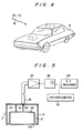
- Fig. 4 shows that when external electromagnetic waves W such as broadcast waves pass through a vehicle body B made of conductive metal, surface currents I are induced at various points of the vehicle body B at levels corresponding to the intensities of electromagnetic waves passing therethrough.
- the present invention is aimed only at electromagnetic waves which belong to relatively high frequency bands of 50MHz or greater, such as FM waves, television waves and others.
- the distribution of the surface currents induced on the vehicle body by electromangetic waves within the above described particular wave bands is measured with a view to identifying a position on the vehicle body which is high in surface current density and low in noise and at which a pick-up may be located.
- the distribution of surface currents is determined by simulation using a computer and also by measuring actual intensities of surface currents at various positions on a vehicle.
- the measurement is carried out by the use of a probe which can operate in accordance with the same principle as that of a pick-up actually located on the vehicle body at the desired position. Such a probe is moved on the vehicle body over the entire surface thereof to measure the level of surface currents at various positions on the vehicle body.
- Fig. 5 shows the general construction of such a probe P which is constructed in accordance with substantially the same principle as that of the pick-up described hereinafter.
- the probe P is composed of a casing 10 of electrically conductive material for preventing interference by external electromagnetic waves and a loop coil 12 is secured to the interior of the casing 10.
- the casing 10 includes an opening 10a formed therein through which a portion of the loop coil 12 is exposed to the exterior.
- the exposed portion of the loop coil 12 is positioned in close proximity to the surface of the vehicle body B to detect magnetic flux induced by surface currents on the vehicle body B.
- Another portion of the loop coil 12 is connected to the casing 10 through a short-circuiting line 14.
- the loop coil 12 further includes an output end 16 connected to a core 20 in a coaxial cable 18.
- Still another portion of the loop coil 12 includes a capacitor 22 for causing the frequency of the loop coil 12 to resonate relative to the desired frequency to be measured so as to increase the efficiency of the pick-up.
- the output of the probe P is amplified by a high-frequency voltage amplifier 24 and the resulting output voltage is measured by a high-frequency voltmeter 26.
- This coil voltage output is read through a value indicated by the high-frequency voltmeter 26 and a voltage corresponding to the value indicated by the voltmeter 26 is recorded by an XY recorder 28 to provide the distribution of surface currents at the various positions on the vehicle body.
- Signals indicative of various positions are fed from a potentiometer 30 to the input of the XY recorder 28, whereby the high-frequency surface currents at each of the positions thereof can be ascertained.
- Fig. 6 shows a declination ⁇ which is formed by the high-frequency surface currents I and the loop coil 12 of the pick-up, and, as shown in this figure, a magnetic flux ⁇ caused by the currents I crosses the loop coil 12 so as to generate a detected voltage V at the loop coil 12.
- ⁇ is 0, that is, when the surface currents I are parallel to the loop coil 12 of the pick-up, the maximum level of voltage can be obtained and the direction in which the surface currents I flow when the maximum voltage is obtained can be found by rotating the probe P at the respective points of measurement.
- Figs. 8 and 9 shows the magnitude and the direction of the high-frequency surface currents generated at the respective positions on the vehicle body at a frequency of 80MHz which is found on the basis of both the results obtained from measurement by the probe P and a computer simulation.
- the magnitude of the surface currents is distributed in such a manner that current density is high at the portions along the edge of each flat portion of the vehicle body while it is extremely low at the center of each flat portion thereof.
- Fig. 10 is a graph showing the distribution of the surface currents which appear along the line between points A and B on the trunk (boot) lid. As clearly shown in this figure, the distribution characteristics are such that the maximum level of currents flow at the opposite ends of the lid while the current value decreases from the ends of the lid to the center thereof.
- the disposition of the pick-up in the vicinity of a peripheral edge portion of the trunk lid enables the detection of the currents concentratedly flowing near this peripheral edge portion.
- Fig. 11 shows the current distribution along the chain line shown in Fig. 8 running over the roof plate of the vehicle body
- Fig. 12 shows that along the same chain line where it runs over the bonnet of the engine compartment.
- the maximum level of current is conducted at both ends of the roof plate and the engine compartment bonnet, respectively, and, conversely, the current values decrease toward the center thereof.
- broadcast waves can be picked up with proper sensitivity in the vicinity of each peripheral edge of the vehicle body.
- the pick-up mounting position is not limited to the bonnet or the roof plate noted above and the system may be applied to a pillar or a fender (wing) in a similar manner.
- the pick-up is mounted in such a manner that, as an example, the length of the loop antenna is located in close proximity to and along the peripheral edge portion of a vehicle body portion).
- the pick-up mounting zone along the peripheral edge is set within a range which is dependant upon the carrier frequencies of broadcast waves whereby excellent sensitivity can be achieved in practical terms.
- the distribution characteristics shown in Figs. 10 to 12 are those of the vehicle body currents with respect to an FM broadcast frequency of 80 MHz in which, as described above, the value of each surface current is lowered in accordance with the distance from the end or edge of each vehicle body portion. As can be seen from these characteristics, since a satisfactory sensitivity can be actually achieved within a current lowering range of 6 dB or less, remarkably excellent sensitivity can be accomplished within 4.5 cm from the edge.
- the pick-up is disposed in close proximity to an edge portion of a metal vehicle body portion, and is preferably located within the above-noted margin from the edge, thereby accomplishing a proper reception effect.
- the pick-up may be located within 3.6 cm from the edge of the vehicle body portion. Hence, as the carrier frequency f increases, the pick-up mounting position is limited to a progressively narrower area extremely close to the edge.
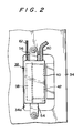
- Figs. 1 to 3 show one preferred embodiment in accordance with the present invention in which the pick-up is disposed in close proximity to the rear edge of the roof plate.
- Fig. 1 shows a roof plate 32 in an exposed state.
- the metal roof plate 32 with a rear window frame 34 constituting the peripheral edge is connected to a rear glass 36.
- a pick-up 38 includes a casing 40 made of metal for preventing external magnetic flux from reaching the interior, while the interior of the casing 40 contains a loop antenna 42, thus constituting an electromagentic coupling type of pick-up.
- the construction is analogous to the foregoing probe containing a loop coil which, as described above, is used to examine the surface current distribution on the vehicle body.
- Fig. 3 is a lateral cross-sectional view in which the pick-up 38 is secured to the roof plate 32.
- the roof plate 32 includes a roof panel 44 and the rear window frame 34 is secured to one end of the roof panel 44.
- the rear glass 36 is secured to the roof panel 44 by a fastener 46 and a dam 48 which airtightly adhere to each other by the medium of an adhesive 50.
- a moulding 52 is secured between the roof panel 44 and the rear glass 36.
- a roof trim (garnish) 64 is secured to the roof panel 44 inward of the rear window frame 34 of the roof plate 32 (inside the vehicle body), and an edge moulding 66 is fixed to the ends of the roof trim 64 and the rear window frame 34 in combination.
- An edge-moulding mounting retainer 68 for mounting the edge moulding 66 is disposed in the space between the rear window frame 34 and the roof trim 64.
- the retainer 68 is separated from the rear window frame 34 by spacers 70 and 72 thereby facilitating the concentration of surface currents.
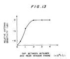
- Fig. 13 is a graph showing variations in antenna sensitivity with respect to the gap between the rear window frame 34 and the retainer 68, that is, the varied values of a surface current density which reaches the maximum at about 2 ⁇ 10 ⁇ 3 ⁇ wavelength.
- the degree of concentration of surface currents flowing at each edge of the vehicle body can be enhanced by separating the retainer 68 from the rear window frame 34 by a distance corresponding to the above mentioned gap.
- An opening 34a is formed in a portion of the rear window frame 34 and the casing 40 of the pick-up 38 is inserted into the opening 34a in such a manner that the loop antenna 42 of the pick-up 38 is disposed in face-to-face relationship with the edge of the retainer 68.
- the loop antenna 42 of the pick-up 38 is disposed in close proximity to the edge of the retainer 68 and along the length thereof.
- the retainer 68 is separated from the rear window frame 34 by a dimension approximately equivalent to (2 ⁇ 10 ⁇ 3 ⁇ wavelength).
- the longitudinal length is made substantially equal to a wavelength in the television band, for example, about half a wavelength with respect to a low frequency band (1 to 3 chs in Japan) of the VHF band, about one wavelength with respect to a high frequency band (4 to 12 chs in Japan) of the same band and about (2 to 4 ⁇ wavelength) with respect to the UHF band. Therefore, concentration of surface currents in these frequency bands is further facilitated, whereby high sensitivity reception can be accomplished.
- the casing 40 of the pick-up 38 has an opening 40a through which the longitudinal side of the loop antenna 42 is exposed, and the portion of the loop antenna 42 which is exposed through the casing 40 made of electrically conductive material is disposed in close proximity to and in face-to-face relationship with the edge of the edge-moulding mounting retainer 68.
- magnetic flux induced by high-frequency surface currents flowing in the edge portion of the retainer 68 is positively captured by the loop antenna 42 within the casing 40, and additionally, the casing 40 positively prevents external magnetic flux from reaching the interior thereof, thereby enabling the currents induced on the vehicle body to be detected with high sensitivity by the pick-up 38.
- L-shaped brackets 54 and 56 are connected to the opposite ends of the casing 40 by using fastening means such as bolts and the brackets 54 and 56 are threadedly secured to the rear window frame 34.
- a circuit section 58 which is connected to the loop antenna 42 is incorporated into the casing 40 of the pick-up 38 and a detected signal is processed by a preamplifier or similar arranged in the circuit section 58. Furthermore, the high-frequency detected signal thus obtained is taken off through a coaxial cable 60 and is processed by the same circuit as that used in the above-mentioned measurement of surface current distribution.
- the circuit section 58 is supplied with electricity and signals for controlling the circuit section 58 through a cable 62.
- the loop antenna 42 is constituted by a single-turn antenna and has a structure in which the coil thereof is insulation-coated so that it may be disposed in physical contact with the edge-moulding mounting retainer 68 in electrically isolated relationship therebetween, being forced against the end surface of the retainer 68. This further strongly forces magnetic flux caused by surface currents to cross the loop antenna 42.
- the side of the loop antenna 42 which is exposed through the casing 40 is disposed within 4.5 cm from the edge of the retainer 68, thereby enabling the detection of vehicle body surface currents flowing in the edge portion of the retainer 68 due to the induction caused by broadcast waves of 50 MHz or greater, particularly FM-band or TV-band frequencies.
- Fig. 9 clearly shows the direction of flow of the vehicle body surface currents in this instance in which the currents flow along the edge portions of the vehicle body. Therefore, in accordance with this embodiment, the loop antenna 46 is disposed such that the length thereof extends along the edge of the retainer 68.
- a broadcast wave receiving antenna for relatively high frequency bands such as the VHF band is formed by utilizing high-frequency surface currents developed at particular portions of a vehicle body, specifically in the peripheral edge of the edge-moulding mounting retainer whose longitudinal length is substantially equal to the wavelength of the television band, thus enabling a high-density, high-quality and low-noise detection.
Landscapes
- Engineering & Computer Science (AREA)
- Remote Sensing (AREA)
- Details Of Aerials (AREA)
- Support Of Aerials (AREA)
- Fittings On The Vehicle Exterior For Carrying Loads, And Devices For Holding Or Mounting Articles (AREA)
Priority Applications (1)
| Application Number | Priority Date | Filing Date | Title |
|---|---|---|---|
| AT86302159T ATE95343T1 (de) | 1985-03-27 | 1986-03-24 | Fahrzeugantennensystem. |
Applications Claiming Priority (2)
| Application Number | Priority Date | Filing Date | Title |
|---|---|---|---|
| JP64690/85 | 1985-03-27 | ||
| JP60064690A JPS61222303A (ja) | 1985-03-27 | 1985-03-27 | 自動車用アンテナ装置 |
Publications (3)
| Publication Number | Publication Date |
|---|---|
| EP0196209A2 EP0196209A2 (en) | 1986-10-01 |
| EP0196209A3 EP0196209A3 (en) | 1988-06-01 |
| EP0196209B1 true EP0196209B1 (en) | 1993-09-29 |
Family
ID=13265397
Family Applications (1)
| Application Number | Title | Priority Date | Filing Date |
|---|---|---|---|
| EP86302159A Expired - Lifetime EP0196209B1 (en) | 1985-03-27 | 1986-03-24 | Automobile antenna system |
Country Status (7)
| Country | Link |
|---|---|
| US (1) | US4792807A (da) |
| EP (1) | EP0196209B1 (da) |
| JP (1) | JPS61222303A (da) |
| AT (1) | ATE95343T1 (da) |
| CA (1) | CA1252882A (da) |
| DE (1) | DE3689079T2 (da) |
| DK (1) | DK171851B1 (da) |
Families Citing this family (4)
| Publication number | Priority date | Publication date | Assignee | Title |
|---|---|---|---|---|
| DE102005050256A1 (de) * | 2005-10-20 | 2007-05-16 | Gm Global Tech Operations Inc | Kraftfahrzeug mit optimal positioniertem Antennenverbindungsstecker |
| US7973722B1 (en) * | 2007-08-28 | 2011-07-05 | Apple Inc. | Electronic device with conductive housing and near field antenna |
| US20130342326A1 (en) * | 2012-06-22 | 2013-12-26 | United States Of America As Represented By The Administrator Of The National Aeronautics And Spac | Systems, apparatuses, and methods for transparent and ubiquitous sensing technology |
| CN112105147B (zh) * | 2020-09-24 | 2021-11-16 | 湖北亿咖通科技有限公司 | 一种车载娱乐系统主机 |
Citations (1)
| Publication number | Priority date | Publication date | Assignee | Title |
|---|---|---|---|---|
| EP0181120A2 (en) * | 1984-10-26 | 1986-05-14 | Toyota Jidosha Kabushiki Kaisha | Automobile antenna system |
Family Cites Families (64)
| Publication number | Priority date | Publication date | Assignee | Title |
|---|---|---|---|---|
| FR824159A (fr) * | 1936-07-11 | 1938-02-02 | Opel Adam Ag | Antenne pour la réception d'émissions de t. s. f. dans les voitures automobiles |
| US2200674A (en) * | 1939-05-04 | 1940-05-14 | Jr Eugene F Mcdonald | Radio apparatus |
| US2404093A (en) * | 1941-06-28 | 1946-07-16 | Rca Corp | Antenna |
| US2474794A (en) * | 1944-01-17 | 1949-06-28 | Measurements Corp | Attenuator |
| US2481978A (en) * | 1947-01-22 | 1949-09-13 | Joseph B Clough | Automobile radio coupler and method of communication |
| US2520986A (en) * | 1947-10-22 | 1950-09-05 | Motorola Inc | Vehicular antenna system |
| US2575471A (en) * | 1950-04-13 | 1951-11-20 | Philco Corp | Vehicular antenna system |
| DE889618C (de) * | 1951-09-27 | 1953-09-10 | Lorenz C Ag | Kraftwagenantennenanlage |
| US2740113A (en) * | 1952-01-03 | 1956-03-27 | Bendix Aviat Corp | Magnetic antenna systems |
| US2774811A (en) * | 1954-03-02 | 1956-12-18 | Shanok Abraham | Antenna and trim |
| US3007164A (en) * | 1955-04-22 | 1961-10-31 | Ross A Davis | Slot antenna which is fed at two points |
| US2971191A (en) * | 1955-07-18 | 1961-02-07 | Ross A Davis | Slot type antenna having an autotransformer coupling circuit |
| US2950479A (en) * | 1955-12-05 | 1960-08-23 | Gen Electric | Loop antenna utilizing conductive cabinet |
| US3066293A (en) * | 1956-03-16 | 1962-11-27 | Ross A Davis | Antenna system with output means in parallel with resonating means |
| US2859441A (en) * | 1957-06-21 | 1958-11-04 | Rosenbaum Jacob | Automobile radio antenna |
| DE1131762B (de) * | 1957-10-15 | 1962-06-20 | Arnaldo Piccinini | Rundfunkempfaenger mit in Rahmenbauart ausgebildeter und einen Ferritkern aufweisender Gehaeuseantenne fuer Kraftfahzeuge |
| US3210766A (en) * | 1962-02-15 | 1965-10-05 | Ralph O Parker | Slot type antenna with tuning circuit |
| US3364487A (en) * | 1964-12-01 | 1968-01-16 | Rosario J. Maheux | Portable radio receiver antenna coupler set |
| DE1949828A1 (de) * | 1968-10-04 | 1970-04-30 | Portenseigne Ets Marcel | Verfahren und Vorrichtung zum Empfangen radiofrequenter Signale |
| JPS4836583B1 (da) * | 1969-06-13 | 1973-11-06 | ||
| JPS5033076Y1 (da) * | 1969-12-09 | 1975-09-26 | ||
| DE7015306U (de) * | 1970-04-24 | 1970-09-24 | Kolbe & Co Hans | Kraftfahrzeugantenne. |
| US3717876A (en) * | 1971-04-23 | 1973-02-20 | Volkers Res Corp | Ferrite antenna coupled to radio frequency currents in vehicle body |
| US3742508A (en) * | 1971-06-01 | 1973-06-26 | Gen Motors Corp | Inconspicuous vehicle mounted radio antenna |
| US3823403A (en) * | 1971-06-09 | 1974-07-09 | Univ Ohio State Res Found | Multiturn loop antenna |
| US3794997A (en) * | 1971-09-30 | 1974-02-26 | Toyota Motor Co Ltd | Vehicle with apparatus for detecting potential collisions |
| HU170360B (da) * | 1973-05-23 | 1977-05-28 | ||
| JPS5322418A (en) * | 1973-07-09 | 1978-03-01 | Mita Industrial Co Ltd | Multicolor diazo copying method |
| US3916413A (en) * | 1973-12-21 | 1975-10-28 | Ross Alan Davis | Remotely tuned conductive-body antenna system |
| US3961330A (en) * | 1973-12-21 | 1976-06-01 | Ross Alan Davis | Antenna system utilizing currents in conductive body |
| US3961292A (en) * | 1974-01-02 | 1976-06-01 | Ross Alan Davis | Radio frequency transformer |
| US3972048A (en) * | 1974-11-29 | 1976-07-27 | Ross Alan Davis | FM-AM windshield antenna |
| US4003056A (en) * | 1975-05-20 | 1977-01-11 | Ross Alan Davis | Windshield antenna system with resonant element and cooperating resonant conductive edge |
| US4080603A (en) * | 1976-07-12 | 1978-03-21 | Howard Belmont Moody | Transmitting and receiving loop antenna with reactive loading |
| JPS5334826A (en) * | 1976-09-10 | 1978-03-31 | Nippon Chem Ind Co Ltd:The | Production of stabilized iron oxide pigment |
| DE2701921A1 (de) * | 1977-01-19 | 1978-07-20 | Angel Dr Ing Jotzoff | Dem wagen integriertes antennengebilde insbesondere fuer autoradios |
| DE2733478B2 (de) * | 1977-07-25 | 1980-04-17 | Hans Heinrich Prof. Dr. Dr.-Ing.E.H. 8035 Gauting Meinke | Antenne in Form eines Kraftfahrzeuges |
| DE2745475A1 (de) * | 1977-10-08 | 1979-04-12 | Juergen Fischer | Antenne fuer kraftfahrzeuge |
| JPS54128653A (en) * | 1978-03-30 | 1979-10-05 | Nippon Gakki Seizo Kk | Antenna unit for receiver |
| DE2821202A1 (de) * | 1978-05-13 | 1979-11-22 | Juergen Keck | Durch eine kapazitaetsdiode abgestimmte elektronische autoantenne |
| US4217591A (en) * | 1978-09-20 | 1980-08-12 | The United States Of America As Represented By The Secretary Of The Army | High frequency roll-bar loop antenna |
| JPS5827681B2 (ja) * | 1978-09-29 | 1983-06-10 | 日本国有鉄道 | 車両用誘導無線ル−プアンテナの取付構造 |
| JPS5588407A (en) * | 1978-12-25 | 1980-07-04 | Matsushita Electric Ind Co Ltd | Antenna device |
| US4317121A (en) * | 1980-02-15 | 1982-02-23 | Lockheed Corporation | Conformal HF loop antenna |
| JPS56156031A (en) * | 1980-05-07 | 1981-12-02 | Nissan Motor Co Ltd | Diversity receiver for vehicle |
| JPS56168441A (en) * | 1980-05-30 | 1981-12-24 | Nissan Motor Co Ltd | Diversity receiver for car |
| US4339827A (en) * | 1980-11-25 | 1982-07-13 | Rca Corporation | Automatic tuning circuit arrangement with switched impedances |
| JPS5870640A (ja) * | 1981-10-22 | 1983-04-27 | Toyota Motor Corp | ダイバ−シテイ受信システム |
| JPS5870642A (ja) * | 1981-10-22 | 1983-04-27 | Toyota Motor Corp | 自動車用受信装置 |
| JPS5944861A (ja) * | 1982-09-07 | 1984-03-13 | Fujitsu Ltd | 半導体装置およびその製造方法 |
| US4499606A (en) * | 1982-12-27 | 1985-02-12 | Sri International | Reception enhancement in mobile FM broadcast receivers and the like |
| US4566133A (en) * | 1982-12-27 | 1986-01-21 | Commtech International | Switched diversity method and apparatus for FM receivers |
| US4506267A (en) * | 1983-01-26 | 1985-03-19 | Geophysical Survey Systems, Inc. | Frequency independent shielded loop antenna |
| JPS59181732A (ja) * | 1983-03-31 | 1984-10-16 | Toshiba Corp | 携帯用無線機におけるダイバ−シチ−受信方式 |
| JPS59195811A (ja) * | 1983-04-20 | 1984-11-07 | Nippon Denso Co Ltd | 内燃機関用同時点火コイル |
| JPS601010A (ja) * | 1983-06-15 | 1985-01-07 | Mitsubishi Heavy Ind Ltd | 車両空調装置 |
| JPS601012A (ja) * | 1983-06-17 | 1985-01-07 | Nissan Motor Co Ltd | 車両用空調装置 |
| JPS601011A (ja) * | 1983-06-17 | 1985-01-07 | Nissan Motor Co Ltd | 車両用空調装置 |
| JPS601009A (ja) * | 1983-06-18 | 1985-01-07 | Kayaba Ind Co Ltd | 車両の姿勢制御方法 |
| JPS601008A (ja) * | 1983-06-20 | 1985-01-07 | Tokico Ltd | 車高調整用緩衝器 |
| JPS60129464A (ja) * | 1983-12-17 | 1985-07-10 | Riken Corp | カム駒及びその製造方法 |
| JPS60169204A (ja) * | 1984-10-09 | 1985-09-02 | Toyota Motor Corp | 車両用アンテナ装置 |
| JPS60172804A (ja) * | 1984-10-09 | 1985-09-06 | Toyota Motor Corp | 車両用アンテナ装置 |
| CA1254654A (en) * | 1984-11-15 | 1989-05-23 | Junzo Ohe | Automobile antenna system |
-
1985
- 1985-03-27 JP JP60064690A patent/JPS61222303A/ja active Pending
-
1986
- 1986-03-21 CA CA000504749A patent/CA1252882A/en not_active Expired
- 1986-03-24 DE DE86302159T patent/DE3689079T2/de not_active Expired - Fee Related
- 1986-03-24 EP EP86302159A patent/EP0196209B1/en not_active Expired - Lifetime
- 1986-03-24 AT AT86302159T patent/ATE95343T1/de not_active IP Right Cessation
- 1986-03-25 US US06/843,630 patent/US4792807A/en not_active Expired - Lifetime
- 1986-03-26 DK DK141886A patent/DK171851B1/da not_active IP Right Cessation
Patent Citations (1)
| Publication number | Priority date | Publication date | Assignee | Title |
|---|---|---|---|---|
| EP0181120A2 (en) * | 1984-10-26 | 1986-05-14 | Toyota Jidosha Kabushiki Kaisha | Automobile antenna system |
Also Published As
| Publication number | Publication date |
|---|---|
| CA1252882A (en) | 1989-04-18 |
| DE3689079D1 (de) | 1993-11-04 |
| DK141886A (da) | 1986-09-28 |
| EP0196209A3 (en) | 1988-06-01 |
| US4792807A (en) | 1988-12-20 |
| DK171851B1 (da) | 1997-07-07 |
| JPS61222303A (ja) | 1986-10-02 |
| ATE95343T1 (de) | 1993-10-15 |
| DK141886D0 (da) | 1986-03-26 |
| EP0196209A2 (en) | 1986-10-01 |
| DE3689079T2 (de) | 1994-02-10 |
Similar Documents
| Publication | Publication Date | Title |
|---|---|---|
| EP0183523B1 (en) | Automobile antenna system | |
| EP0187446B1 (en) | Automobile antenna | |
| US4811024A (en) | Automobile antenna | |
| EP0181120B1 (en) | Automobile antenna system | |
| US4717920A (en) | Automobile antenna system | |
| EP0223398B1 (en) | Vehicle antenna system | |
| EP0196209B1 (en) | Automobile antenna system | |
| EP0180462B1 (en) | Automobile antenna system | |
| EP0182614B1 (en) | Automobile antenna system | |
| JPS61120504A (ja) | 自動車用アンテナのピツクアツプ | |
| JPS61127204A (ja) | 自動車用アンテナ装置 | |
| JPS61129907A (ja) | 自動車用アンテナ装置 | |
| JPH0652849B2 (ja) | 自動車用アンテナのピツクアツプ | |
| JPS61127206A (ja) | 自動車用アンテナ装置 | |
| JPS61136303A (ja) | 自動車用アンテナ装置 | |
| JPS61112403A (ja) | 自動車用アンテナ装置 | |
| JPS61105907A (ja) | 自動車用アンテナ装置 | |
| JPS62104301A (ja) | 自動車用アンテナ装置 | |
| JPS62102606A (ja) | 自動車用アンテナ装置 | |
| JPS61105906A (ja) | 自動車用アンテナ装置 | |
| JPS61129904A (ja) | 自動車用アンテナ装置 | |
| JPS62104204A (ja) | 自動車用アンテナ装置 | |
| JPH0612847B2 (ja) | 自動車用アンテナ装置 | |
| JPS61129906A (ja) | 車両用アンテナ装置 | |
| JPS623506A (ja) | 自動車用アンテナ装置 |
Legal Events
| Date | Code | Title | Description |
|---|---|---|---|
| PUAI | Public reference made under article 153(3) epc to a published international application that has entered the european phase |
Free format text: ORIGINAL CODE: 0009012 |
|
| AK | Designated contracting states |
Kind code of ref document: A2 Designated state(s): AT CH DE FR GB LI SE |
|
| PUAL | Search report despatched |
Free format text: ORIGINAL CODE: 0009013 |
|
| AK | Designated contracting states |
Kind code of ref document: A3 Designated state(s): AT CH DE FR GB LI SE |
|
| 17P | Request for examination filed |
Effective date: 19880920 |
|
| 17Q | First examination report despatched |
Effective date: 19910214 |
|
| GRAA | (expected) grant |
Free format text: ORIGINAL CODE: 0009210 |
|
| AK | Designated contracting states |
Kind code of ref document: B1 Designated state(s): AT CH DE FR GB LI SE |
|
| PG25 | Lapsed in a contracting state [announced via postgrant information from national office to epo] |
Ref country code: SE Effective date: 19930929 Ref country code: LI Effective date: 19930929 Ref country code: CH Effective date: 19930929 Ref country code: AT Effective date: 19930929 |
|
| REF | Corresponds to: |
Ref document number: 95343 Country of ref document: AT Date of ref document: 19931015 Kind code of ref document: T |
|
| REF | Corresponds to: |
Ref document number: 3689079 Country of ref document: DE Date of ref document: 19931104 |
|
| ET | Fr: translation filed | ||
| REG | Reference to a national code |
Ref country code: CH Ref legal event code: PL |
|
| PLBE | No opposition filed within time limit |
Free format text: ORIGINAL CODE: 0009261 |
|
| STAA | Information on the status of an ep patent application or granted ep patent |
Free format text: STATUS: NO OPPOSITION FILED WITHIN TIME LIMIT |
|
| 26N | No opposition filed | ||
| PGFP | Annual fee paid to national office [announced via postgrant information from national office to epo] |
Ref country code: GB Payment date: 19960315 Year of fee payment: 11 Ref country code: FR Payment date: 19960315 Year of fee payment: 11 |
|
| PGFP | Annual fee paid to national office [announced via postgrant information from national office to epo] |
Ref country code: DE Payment date: 19960328 Year of fee payment: 11 |
|
| PG25 | Lapsed in a contracting state [announced via postgrant information from national office to epo] |
Ref country code: GB Effective date: 19970324 |
|
| GBPC | Gb: european patent ceased through non-payment of renewal fee |
Effective date: 19970324 |
|
| PG25 | Lapsed in a contracting state [announced via postgrant information from national office to epo] |
Ref country code: FR Free format text: LAPSE BECAUSE OF NON-PAYMENT OF DUE FEES Effective date: 19971128 |
|
| PG25 | Lapsed in a contracting state [announced via postgrant information from national office to epo] |
Ref country code: DE Effective date: 19971202 |
|
| REG | Reference to a national code |
Ref country code: FR Ref legal event code: ST |