EP0201255A2 - Tête magnétique et son procédé de fabrication - Google Patents
Tête magnétique et son procédé de fabrication Download PDFInfo
- Publication number
- EP0201255A2 EP0201255A2 EP86303186A EP86303186A EP0201255A2 EP 0201255 A2 EP0201255 A2 EP 0201255A2 EP 86303186 A EP86303186 A EP 86303186A EP 86303186 A EP86303186 A EP 86303186A EP 0201255 A2 EP0201255 A2 EP 0201255A2
- Authority
- EP
- European Patent Office
- Prior art keywords
- magnetic
- gap
- head
- magnetic alloy
- ferrite
- Prior art date
- Legal status (The legal status is an assumption and is not a legal conclusion. Google has not performed a legal analysis and makes no representation as to the accuracy of the status listed.)
- Granted
Links
Images


Classifications
-
- G—PHYSICS
- G11—INFORMATION STORAGE
- G11B—INFORMATION STORAGE BASED ON RELATIVE MOVEMENT BETWEEN RECORD CARRIER AND TRANSDUCER
- G11B5/00—Recording by magnetisation or demagnetisation of a record carrier; Reproducing by magnetic means; Record carriers therefor
- G11B5/127—Structure or manufacture of heads, e.g. inductive
-
- G—PHYSICS
- G11—INFORMATION STORAGE
- G11B—INFORMATION STORAGE BASED ON RELATIVE MOVEMENT BETWEEN RECORD CARRIER AND TRANSDUCER
- G11B5/00—Recording by magnetisation or demagnetisation of a record carrier; Reproducing by magnetic means; Record carriers therefor
- G11B5/127—Structure or manufacture of heads, e.g. inductive
- G11B5/187—Structure or manufacture of the surface of the head in physical contact with, or immediately adjacent to the recording medium; Pole pieces; Gap features
- G11B5/1871—Shaping or contouring of the transducing or guiding surface
-
- G—PHYSICS
- G11—INFORMATION STORAGE
- G11B—INFORMATION STORAGE BASED ON RELATIVE MOVEMENT BETWEEN RECORD CARRIER AND TRANSDUCER
- G11B5/00—Recording by magnetisation or demagnetisation of a record carrier; Reproducing by magnetic means; Record carriers therefor
- G11B5/127—Structure or manufacture of heads, e.g. inductive
- G11B5/187—Structure or manufacture of the surface of the head in physical contact with, or immediately adjacent to the recording medium; Pole pieces; Gap features
-
- Y—GENERAL TAGGING OF NEW TECHNOLOGICAL DEVELOPMENTS; GENERAL TAGGING OF CROSS-SECTIONAL TECHNOLOGIES SPANNING OVER SEVERAL SECTIONS OF THE IPC; TECHNICAL SUBJECTS COVERED BY FORMER USPC CROSS-REFERENCE ART COLLECTIONS [XRACs] AND DIGESTS
- Y10—TECHNICAL SUBJECTS COVERED BY FORMER USPC
- Y10T—TECHNICAL SUBJECTS COVERED BY FORMER US CLASSIFICATION
- Y10T29/00—Metal working
- Y10T29/49—Method of mechanical manufacture
- Y10T29/49002—Electrical device making
- Y10T29/4902—Electromagnet, transformer or inductor
- Y10T29/49021—Magnetic recording reproducing transducer [e.g., tape head, core, etc.]
- Y10T29/49032—Fabricating head structure or component thereof
- Y10T29/49036—Fabricating head structure or component thereof including measuring or testing
- Y10T29/49043—Depositing magnetic layer or coating
-
- Y—GENERAL TAGGING OF NEW TECHNOLOGICAL DEVELOPMENTS; GENERAL TAGGING OF CROSS-SECTIONAL TECHNOLOGIES SPANNING OVER SEVERAL SECTIONS OF THE IPC; TECHNICAL SUBJECTS COVERED BY FORMER USPC CROSS-REFERENCE ART COLLECTIONS [XRACs] AND DIGESTS
- Y10—TECHNICAL SUBJECTS COVERED BY FORMER USPC
- Y10T—TECHNICAL SUBJECTS COVERED BY FORMER US CLASSIFICATION
- Y10T29/00—Metal working
- Y10T29/49—Method of mechanical manufacture
- Y10T29/49002—Electrical device making
- Y10T29/4902—Electromagnet, transformer or inductor
- Y10T29/49021—Magnetic recording reproducing transducer [e.g., tape head, core, etc.]
- Y10T29/49032—Fabricating head structure or component thereof
- Y10T29/49048—Machining magnetic material [e.g., grinding, etching, polishing]
- Y10T29/49052—Machining magnetic material [e.g., grinding, etching, polishing] by etching
-
- Y—GENERAL TAGGING OF NEW TECHNOLOGICAL DEVELOPMENTS; GENERAL TAGGING OF CROSS-SECTIONAL TECHNOLOGIES SPANNING OVER SEVERAL SECTIONS OF THE IPC; TECHNICAL SUBJECTS COVERED BY FORMER USPC CROSS-REFERENCE ART COLLECTIONS [XRACs] AND DIGESTS
- Y10—TECHNICAL SUBJECTS COVERED BY FORMER USPC
- Y10T—TECHNICAL SUBJECTS COVERED BY FORMER US CLASSIFICATION
- Y10T29/00—Metal working
- Y10T29/49—Method of mechanical manufacture
- Y10T29/49002—Electrical device making
- Y10T29/4902—Electromagnet, transformer or inductor
- Y10T29/49021—Magnetic recording reproducing transducer [e.g., tape head, core, etc.]
- Y10T29/49032—Fabricating head structure or component thereof
- Y10T29/49055—Fabricating head structure or component thereof with bond/laminating preformed parts, at least two magnetic
- Y10T29/49057—Using glass bonding material
-
- Y—GENERAL TAGGING OF NEW TECHNOLOGICAL DEVELOPMENTS; GENERAL TAGGING OF CROSS-SECTIONAL TECHNOLOGIES SPANNING OVER SEVERAL SECTIONS OF THE IPC; TECHNICAL SUBJECTS COVERED BY FORMER USPC CROSS-REFERENCE ART COLLECTIONS [XRACs] AND DIGESTS
- Y10—TECHNICAL SUBJECTS COVERED BY FORMER USPC
- Y10T—TECHNICAL SUBJECTS COVERED BY FORMER US CLASSIFICATION
- Y10T29/00—Metal working
- Y10T29/49—Method of mechanical manufacture
- Y10T29/49002—Electrical device making
- Y10T29/4902—Electromagnet, transformer or inductor
- Y10T29/49021—Magnetic recording reproducing transducer [e.g., tape head, core, etc.]
- Y10T29/49032—Fabricating head structure or component thereof
- Y10T29/49067—Specified diverse magnetic materials
Definitions
- the present invention relates to a magnetic head for use in a magnetic recording and reproducing unit and a method of making the same and provides a magnetic head which is excellent in the efficiency of recording data onto a magnetic tape having high coercive force and of reproducing the recorded data, by constructing the magnetic head core by use of both a high permeability ferrite magnetic material and a magnetic alloy having a high saturation magnetic flux density such as a amorphous alloy or the like.
- Magnetic tapes made of Fe or Co alloy powder have been used in practice to improve the recording density but a coercive force Hc of a magnetic tape made of the alloy powder becomes a high value ranging from 1300 to 1500 Oe.
- a metal head wherein a sendust or an amorphous material is used is useful, and conventionally metal heads of a variety construction have been proposed.
- the head core is formed solely of the magnetic alloy, the eddy current loss is great and in case it is used in the range of high frequency such as in video signal, characteristics of the head is remarkably damaged.
- a protrusion is provided on the surface of the ferrite by mechanical processing and a magnetic alloy material is deposited on both side faces of the above protrusion by sputtering to form a head gap by the above alloy magnetic layer so that the head gap and the junction portion between the ferrite and the magnetic alloy are not parallel to each other.
- a magnetic alloy material is deposited on both side faces of the above protrusion by sputtering to form a head gap by the above alloy magnetic layer so that the head gap and the junction portion between the ferrite and the magnetic alloy are not parallel to each other.
- Japanese Patent Laid-Open Publication No. 175122/1983 grooves are provided along a ferrite material, and a magnetic alloy material is filled within the above grooves to obtain the similar effect as in the above prior art. Further, in Japanese Patent Laid-Open Publication No.
- an inclined portion is provided on the surface of the ferrite by mechanical processing, and on the inclined portion a magnetic alloy material is deposited to have a thickness corresponding to a track width of the head, while the head gap portion is formed of a magnetic alloy material, and a head gap and a junction portion formed between the ferrite and the magnetic alloy materials are made unparallel to each other.
- any one of the above-described prior arts involves a complicated process in manufacturing the head, showing disadvantages in applying it to the mass production.
- An object of the present invention is to eliminate the prior art problem caused in the composite type magnetic head composed of the magnetic core made of, for example, a Mn-Zn ferrite and a magnetic alloy such.as amorphous magnetic alloy, i.e. problems of the reduction of SN ratio with respect to recording and reproducing signals due to the action of the junction of both magnetic materials as the pseudo-gap, while providing a magnetic head appropriate for the mass production and a method of making the same.
- Another object of the present invention is to provide a composite type magnetic head composed of the Mn-Zn ferrite and the magnetic alloy such as the amorphous alloy and a method of making the same, wherein, during recording, it is possible to provide a recording magnetic field by which even in a case of the metal tape having the high Hc the magnetic head can sufficiently record thereon while the loss suffered during reproducing can be reduced to thereby obtain a great reproduction output.
- the magnetic core is formed of both a high permeability ferrite and a magnetic alloy, and the magnetic alloy is disposed adjacent the head gap.
- a corrugated portion is provided along the junction portion between the above ferrite and the magnetic alloy, while a height of the corrugated portion is made equivalent to or more than the longest wavelength in both luminance signals and color signals which are recorded on the magnetic recording medium, and a distance between two adjacent crests or bottoms of the corrugation is made smaller than the width of a head track.
- the method of making the magnetic head according to the present invention comprises following seven steps: a first step of forming a parallel slit-like resist coating film having a pitch smaller than a width of track of the magnetic head, on a face Q of a parallelopipedon-shaped block made of the high permeability ferrite, and subjecting the ferrite block to electrolytic etching within an electrolytic solution to form a corrugation having a height not less than a value of the longest wavelength of luminance signals and color signals recorded on a tape; a second step of providing a layer of a magnetic alloy such as an amorphous magnetic alloy by sputtering on said corrugation; a third step of providing grooves along an edge including the magnetic alloy layer, substantially parallelly to said corrugation to define a track having a predetermined width; a fouth step of filling a non-magnetic material in said grooves, and polishing said face Q to form a mirror-like face to thereby provide a first magnetic core portion; a fifth step of
- the magnetic core is formed by use of both high permeability ferrite and magnetic alloy, a head gap portion being formed of the magnetic alloy.
- the notched grooves are provided at both end portions of the gap, and within the groove a non-magnetic material such as glass or the like is filled.
- a length of the magnetic alloy from the surface of the head in the direction of the depth of the gap is made smaller than a distance between the surface of the head and the lower end of a window for a coil winding and also smaller than a length of the notched groove with respect to the direction of depth of the gap.
- Figs. la and lb are enlarged perspective views illustrating an example of the magnetic head according to the invention, in which Fig. la there are removed coil windings 10 and terminals 12.
- reference numerals 1 and 2 show the magnetic core made of the Mn-Zn ferrite material.
- Magnetic alloys 3 and 4 such as the amorphous alloy of Co82.9 Nb 10.9 Zr 4.0 Ta 2 . 2 or sendust of Fe 85 Si 9 .
- the magnetic head according to the present invention is characterized in that the boundary portion between magnetic cores 1 and 2 and the magnetic alloys 3 and 4 is shaped in the alternate concave and convex form (corrugated form) and in that a height D of 4 to 6 ⁇ m defined between the crest and the bottom thereof is made equivalent to or more than the longest wavelength of the luminance signals and the color signals existing in video signals which are recorded onto the magnetic tape.
- a height D of 4 to 6 ⁇ m defined between the crest and the bottom thereof is made equivalent to or more than the longest wavelength of the luminance signals and the color signals existing in video signals which are recorded onto the magnetic tape.
- the wavelength of color signals which was converted into a low frequency is the longest, that is, about 5 ⁇ m. Consequently, in this case, the height of the corrugation is made not less than 5 ⁇ m.
- the color signals which are picked up as interface signals at the point A on the junction portion 8 become having an inversed phase in comparison with other interface signals which are picked up at a point B at which the distance L therebetween corresponds to the half wavelength, with the result that they are negated each other, causing no disturbance.
- the interface signals since at points on the junction portions 8 and 8' between magnetic cores 1 and 2 and magnetic alloys 3 and 4 which points are separated by the half wavelength, the interface signals have respectively inversed phases with each other, they are negated as a whole, so that the disturbance caused by the pseudo-gap can be eliminated.
- the magnetic head according to the invention is characterized in that the distance P of about 20 ⁇ m defined between adjacent two crests or bottoms of the corrugation is made smaller than the track width W of about 30 ⁇ m of the head. Consequently, every points on the junctions 8 and 8' will have a point which is offset by the half wavelength somewhere on the junction portion, which therefore allows to negate the interface signals.
- the above distance P is preferably made smaller than the effective width of the track which is recorded onto the magnetic tape.
- the present invention also provides a method for readily making the magnetic head having features as specified above.
- One example of the method is hereinafter described with reference to Fig. 3 and so on.
- a parallel slit-like resist coating layer 26 having a smaller pitch P of about 20 pm than the track width of the video head was formed on the surface A of the Mn-Zn ferrite substrate 25.
- the ferrite substrate thus obtained was subjected to the electrolytic etching within the electrolytic solution, with the result that, as shown in Fig. 3 (b), a parallel slit-like corrugation was formed on the surface Q and the surface of the ferrite substrate 25 exhibits a corrugated surface Q'.
- the pitch P of about 20 ⁇ m of the corrugation becomes equal to the pitch P of the parallel slit-like resist coating film.
- the height D of 4 - 6 ⁇ m of the corrugation can be controlled by the period of time of the electrolytic etching and, as shown above, is made equal to or more than the value of the longest wavelength existing in the video signals which are recorded on the magnetic tape.
- the magnetic alloy 27 having a high saturation magnetic flux density such as an amorphous one was deposited by sputtering to have an appropriate thickness E of 30 - 40 ⁇ m on the surface Q'.
- the thickness E of magnetic alloy 27 is greater than the height D of the corrugation of the surface Q'.
- notched grooves 29 were provided, as shown in Fig. 3 (e), at one edge 28 of the magnetic alloy layer 27 to thereby form track portions 30.
- the width of the track portion 30 was made equal to the width W of about 30 ⁇ m of the track of the head.
- the track portion 30 there is no limitation regarding the positional relationship between the corrugation present at the junction portion located between the ferrite and the magnetic alloy and the track portion 30, because in the track portion 30 there is included a corrugation having at least one cycle in view of the fact that the distance P' of about 20 ⁇ m between adjacent two crests or bottoms thereof is smaller than the width W of about 30 ⁇ m of the track portion 30. Then, as shown in Fig. 3 (f), the molten glass was filled into the notched grooves 29. As the occasion demands, a groove 32 may be provided rearwardly of the ferrite substrate 25, in which groove the glass 31 can be also filled.
- the magnetic head according to the invention was obtained by cutting the gap bar through the substantially central portion of the notched grooves 29 at a predetermined angle relative to the gap 34.
- the corrugation of the substrate 25 is defined parallel to the surface F
- the parallel-slit-like resist coating film 26 may be formed at a certain angle relative to the surface F, as shown in Fig. 4.
- the parallel slit-like resist coating film need not be rectilinear but may be curved as shown in Fig. 5 without nullifying the advantage obtained in the invention.
- the corrugation is formed onto the surface of the ferrite substrate of Fig. 3 by using the large flat ferrite substrate and the magnetic alloy was deposited onto the surface of the corrugation by sputtering, it becomes possible to improve the efficiency of the mass production system.
- points e and f of the convex portion of the ferrite surface can be formed in the sharp angle protrusion, as shown in Fig. 6, by properly selecting the conditions of electrolytic etching.
- the height D thereof can be enlarged to reduce the affect of the pseudo-gap to a great extent.
- the second feature of the present invention is that positions of the convex portions e and f are made asymmetrical relative to the head gap 5. Namely, convex portions e and f are provided at positions where a straight line connecting convex portions e and f does not intersect at a right angle with the head gap 5. In case points of convex portions e and f form sharp angle, the magnetic potential of the protrusion can be increased, so that convex portions e and f are apt to act as gap. However, since, in this invention, the straight line g does not intersect at a right angle with the head gap 5, i.e.
- the track portion 30 When in the manufacturing process of the head in Fig. 3 (e) the track portion 30 is formed, the track portion can be formed irrespectively of the position of the convex portions provided in the junction position between the ferrite substrate 25 and the magnetic alloy 27. Consequently, when the gap bar is formed, as shown in Fig. 3 (g), by making the left and right cores butt against each other, since the position of the convex portion, which is provided at the junction portion between the ferrite material on the magnetic cores and the magnetic alloys, are respectively freely defined, they scarcely have a symmetrical position relative to the gap.
- Figs. 7a and 7b show another embodiment of the magnetic head according to the invention in which Fig. 7a there are removed magnetic coils 10 and terminals 12, wherein the performance of the head is improved.
- the feature of the embodiment, depicted in Fig. 7 is that the thickness of magnetic alloys 3' and 4' disposed on both side of the rear gap 5' is made smaller than that of magnetic alloys 3 and 4 disposed on both sides of the head gap 5.
- the surface of the magnetic alloy on the ferrite substrate 25 is polished in such a way shown in Fig. 8 (a) that the surface of the magnetic alloy 27 was flattened and inclined so that the thickness T 1 of 10 - 25 ⁇ m at side H of the magnetic alloy was made greater than that T 2 of 0 - 5 ⁇ m at the rear portion thereof.
- the inclination of the magnetic alloy was made greater during polishing, as shown in Fig. 8 (b), such that in the vicinity of the rear portion G the protruding portion S of the ferrite substrate 25 was exposed to the surface of the magnetic alloy 27. Then, the head track was formed on the side of magnetic alloy having a greater thickness.
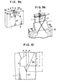
- Figs. 9a and 9b show still another embodiment of the composite type magnetic head composed of the ferrite magnetic material and the magnetic alloy such as the amorphous one magnetic alloy in which Fig. 9a there are removed magnetic coils 10 and terminals 12, which is excellent in the performance of recording and reproducing and is readily produced.
- magnetic alloys 3 and 4 were disposed only on both sides of the head gap 5 and not at the portion of the rear gap 5'.
- Fig. 10 shows an enlarged view when the gap portion is viewed from the direction of the arrow X, wherein a bonding material 6 was removed. 29 denotes a notched groove restricting the width of track of the head.
- the length K of 800 - 900 ⁇ m of magnetic alloys 3 and 4 disposed on both sides of the gap 5 which extends from the surface of the head to the depth of the gap was set to be shorter than a distance J of 700 - 800 ⁇ m defined between the surface of the head and the lower end of the window 7 for coil winding and shorter than the distance I of 500 - 600 ⁇ m defined between the surface of the head and the lower end of the notched groove 29 restricting the width of the track.
- the magnetic alloy having the high saturation magnetic flux density such as the amorphous one was only disposed on the gap portion 5, with the result that during recording there can be obtained a recording magnetic field sufficiently high to effect the recording even with respect to the metal tape having a high Hc.
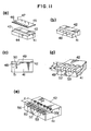
- FIG. 11 shows an example of the manufacturing process of the magnetic head depicted in Fig. 9.
- a recessed portion 43 was defined on a part of one surface 42 of the block 41 of the ferrite magnetic material to define a stepped portion 44.
- the resist film was applied on the surface 42 on the ferrite block 41 and on the surface of the stepped portion 44, a mask 45 having a parallel slit-like pattern 46 was superimposed thereonto and the pattern 46 was printed onto the stepped portion 44 by rediating the light 47.
- the material thus obtained was subjected to the electrolytic etching, as shown in Fig. 3 (b), so that the corrugated surface 48 was formed on the surface of the stepped portion 44 while the surface 42 was maintained in the state of original plane surface without undergoing the etching action.
- Fig. 3 (b) the material thus obtained was subjected to the electrolytic etching, as shown in Fig. 3 (b), so that the corrugated surface 48 was formed on the surface of the stepped portion 44 while the surface 42 was maintained in the state of original plane surface without undergoing the etching action.
- the magnetic alloy 49 such as the amorphous one was deposited by sputtering onto the plane 42 of the ferrite block 41 and on the corrugated surface 48. Subsequently, the surface of the magnetic alloy 49 was polished up to a position as indicated by the dotted line 50 to obtain the magnetic core block in which the magnetic alloy 49 is left on the corrugated surface 48 and in which the magnetic alloy was removed regarding the surface 42. Next, grooves restricting the track which grooves form a predetermined angle 6 of about 12° relative to the polished surface 50 and reach the ferrite material 41 was provided, as shown by the dotted line 51, on the magnetic alloy 49 on the above corrugated surface 48 to obtain the half body of the magnetic core having a shape as depicted in Fig.
- track restricting grooves 52 are sequentially defined within the magnetic alloy 49 to form the track portion 53.
- the depth M of 150 - 200 ⁇ m of the groove 52 was made greater than the thickness N of 10 - 25 ⁇ m of the magnetic alloy 49, while the length I of the groove 52 was made greater than the length K of the magnetic alloy 49.
- the non-magnetic material 54 such as the glass or the like is filled into the grooves 52.
- the window 55 for coil winding was provided on the surface 42. The distance between the lower end of the window 55 and the front surface 56 of the block 41 was made shorter than the length I of the track defining grooves 52.
Landscapes
- Engineering & Computer Science (AREA)
- Manufacturing & Machinery (AREA)
- Magnetic Heads (AREA)
Applications Claiming Priority (8)
| Application Number | Priority Date | Filing Date | Title |
|---|---|---|---|
| JP93014/85 | 1985-04-30 | ||
| JP60093014A JPS61250808A (ja) | 1985-04-30 | 1985-04-30 | 磁気ヘツドおよびその製造方法 |
| JP107372/85 | 1985-05-20 | ||
| JP60107372A JPS61265714A (ja) | 1985-05-20 | 1985-05-20 | 磁気ヘツド |
| JP60147564A JPS628311A (ja) | 1985-07-04 | 1985-07-04 | 磁気ヘツド |
| JP147564/85 | 1985-07-04 | ||
| JP61042239A JPS62200508A (ja) | 1986-02-27 | 1986-02-27 | 磁気ヘツド |
| JP42239/86 | 1986-02-27 |
Publications (3)
| Publication Number | Publication Date |
|---|---|
| EP0201255A2 true EP0201255A2 (fr) | 1986-11-12 |
| EP0201255A3 EP0201255A3 (en) | 1987-08-26 |
| EP0201255B1 EP0201255B1 (fr) | 1991-07-17 |
Family
ID=27461174
Family Applications (1)
| Application Number | Title | Priority Date | Filing Date |
|---|---|---|---|
| EP86303186A Expired - Lifetime EP0201255B1 (fr) | 1985-04-30 | 1986-04-28 | Tête magnétique et son procédé de fabrication |
Country Status (4)
| Country | Link |
|---|---|
| US (2) | US4769898A (fr) |
| EP (1) | EP0201255B1 (fr) |
| KR (1) | KR910000790B1 (fr) |
| DE (1) | DE3680236D1 (fr) |
Cited By (3)
| Publication number | Priority date | Publication date | Assignee | Title |
|---|---|---|---|---|
| DE3741208A1 (de) * | 1986-12-05 | 1988-06-09 | Hitachi Ltd | Magnetkopf-vorrichtung |
| EP0352889A3 (en) * | 1988-07-26 | 1990-12-05 | Matsushita Electric Industrial Co., Ltd. | Magnetic head and method for maufacturing same |
| US6445180B1 (en) * | 2000-06-28 | 2002-09-03 | Baker Hughes Incorporated | Nuclear magnetic resonance tool with active RF spoiler antenna |
Families Citing this family (17)
| Publication number | Priority date | Publication date | Assignee | Title |
|---|---|---|---|---|
| JPS63257904A (ja) * | 1987-04-15 | 1988-10-25 | Pioneer Electronic Corp | 磁気ヘツドの製造方法 |
| US5228185A (en) * | 1988-04-05 | 1993-07-20 | Matsushita Electric Industrial Co., Ltd. | Method of manufacturing a magnetic head |
| US5208965A (en) * | 1989-01-17 | 1993-05-11 | Victor Company Of Japan, Ltd. | Method for producing magnetic head having track regulation grooves formed at tape sliding surface |
| JP2759271B2 (ja) * | 1989-01-17 | 1998-05-28 | 日本ビクター株式会社 | 磁気ヘッドとその製造方法 |
| DE4030326C2 (de) * | 1989-09-27 | 1995-01-12 | Mitsubishi Electric Corp | Gerät zur magnetischen Aufzeichnung und Wiedergabe mit mehreren Verbund-Magnetköpfen und Verfahren zur Herstellung eines bei diesem Gerät verwendbaren Verbund-Magnetkopfes |
| US5267392A (en) * | 1992-03-04 | 1993-12-07 | Ampex Systems Corporation | Method of manufacturing a laminated high frequency magnetic transducer |
| EP0650628B1 (fr) * | 1992-07-17 | 1997-09-24 | Ampex Systems Corporation | Transducteur a tete composite en metal et ferrite et procede de fabrication correspondant |
| JPH0714115A (ja) * | 1993-06-28 | 1995-01-17 | Ngk Insulators Ltd | 磁気ヘッド用コア |
| US6104862A (en) * | 1994-12-19 | 2000-08-15 | Hitachi, Ltd. | Video signal recording and reproducing apparatus compatible with analog and digital video signal recording and reproducing |
| US5768072A (en) * | 1995-06-16 | 1998-06-16 | Sanyo Electric Co., Ltd. | Magnetic head for magnetic recording and reproduction |
| EP0768640A3 (fr) * | 1995-10-13 | 1998-11-11 | Ampex Corporation | Tête magnétique à petit noyau à support latéral non magnétique |
| JPH10247309A (ja) * | 1997-03-05 | 1998-09-14 | Matsushita Electric Ind Co Ltd | 回転ヘッド装置の製造方法,磁気ヘッドユニットの製造方法,回転ヘッド装置および磁気ヘッドユニット |
| FR2774797B1 (fr) * | 1998-02-11 | 2000-03-10 | Commissariat Energie Atomique | Procede de realisation d'un ensemble a plusieurs tetes magnetiques et ensemble a tetes multiples obtenu par ce procede |
| US6950277B1 (en) * | 2002-10-25 | 2005-09-27 | Maxtor Corporation | Concave trailing edge write pole for perpendicular recording |
| US7535674B2 (en) * | 2004-09-09 | 2009-05-19 | Hitachi Global Storage Technologies Netherlands B.V. | Narrow pitch tape head array using an orthogonal backgap |
| US7869160B1 (en) * | 2005-04-27 | 2011-01-11 | Western Digital (Fremont), Llc | Perpendicular recording head with shaped pole surfaces for higher linear data densities |
| JP2012216687A (ja) * | 2011-03-31 | 2012-11-08 | Sony Corp | 受電コイル、受電装置及び非接触電力伝送システム |
Family Cites Families (10)
| Publication number | Priority date | Publication date | Assignee | Title |
|---|---|---|---|---|
| US4425701A (en) * | 1980-10-17 | 1984-01-17 | Matsushita Electric Industrial Co., Ltd. | Methods of making magnetic recording heads |
| JPS5855513A (ja) * | 1981-09-28 | 1983-04-01 | Nippon Kokan Kk <Nkk> | 溶銑の予備処理方法 |
| JPS58161127A (ja) * | 1982-03-19 | 1983-09-24 | Hitachi Ltd | 複合型磁気ヘツドおよびその製造方法 |
| JPS58175122A (ja) * | 1982-04-07 | 1983-10-14 | Hitachi Ltd | 磁気ヘッドおよびその製造方法 |
| JPS58182118A (ja) * | 1982-04-19 | 1983-10-25 | Victor Co Of Japan Ltd | 磁気ヘツド及びその製造法 |
| JPS59207415A (ja) * | 1983-05-11 | 1984-11-24 | Hitachi Ltd | 複合型磁気ヘツドおよびその製造方法 |
| JPS6089807A (ja) * | 1983-10-21 | 1985-05-20 | Sanyo Electric Co Ltd | 磁気ヘツド |
| JPS60125906A (ja) * | 1983-12-10 | 1985-07-05 | Sony Corp | 磁気ヘツド |
| US4819113A (en) * | 1984-03-29 | 1989-04-04 | Sony Corporation | Magnetic transducer head with inclined magnetic gap |
| JPS61126614A (ja) * | 1984-11-21 | 1986-06-14 | Victor Co Of Japan Ltd | 磁気ヘツド及びその製造方法 |
-
1986
- 1986-04-25 KR KR1019860003213A patent/KR910000790B1/ko not_active Expired
- 1986-04-28 DE DE8686303186T patent/DE3680236D1/de not_active Expired - Lifetime
- 1986-04-28 EP EP86303186A patent/EP0201255B1/fr not_active Expired - Lifetime
-
1987
- 1987-04-22 US US07/041,283 patent/US4769898A/en not_active Expired - Lifetime
-
1988
- 1988-04-01 US US07/175,605 patent/US4888658A/en not_active Expired - Fee Related
Cited By (3)
| Publication number | Priority date | Publication date | Assignee | Title |
|---|---|---|---|---|
| DE3741208A1 (de) * | 1986-12-05 | 1988-06-09 | Hitachi Ltd | Magnetkopf-vorrichtung |
| EP0352889A3 (en) * | 1988-07-26 | 1990-12-05 | Matsushita Electric Industrial Co., Ltd. | Magnetic head and method for maufacturing same |
| US6445180B1 (en) * | 2000-06-28 | 2002-09-03 | Baker Hughes Incorporated | Nuclear magnetic resonance tool with active RF spoiler antenna |
Also Published As
| Publication number | Publication date |
|---|---|
| KR860008526A (ko) | 1986-11-15 |
| US4769898A (en) | 1988-09-13 |
| US4888658A (en) | 1989-12-19 |
| DE3680236D1 (de) | 1991-08-22 |
| EP0201255B1 (fr) | 1991-07-17 |
| EP0201255A3 (en) | 1987-08-26 |
| KR910000790B1 (ko) | 1991-02-08 |
Similar Documents
| Publication | Publication Date | Title |
|---|---|---|
| US4769898A (en) | Method of producing a magnetic head | |
| EP0125891B1 (fr) | Tête magnétique de type composé et son procédé de fabrication | |
| US4775909A (en) | Magnetic head using a magnetic thin film and first, second and third core members | |
| US5157569A (en) | Thin film magnetic head | |
| US5003688A (en) | Method of producing a magnetic head core having track-width defining cut outs formed on opposite side of a magnetic gap | |
| GB2204439A (en) | A method of making magnetic heads | |
| US5084129A (en) | Method of producing composite type, metal-in-gap magnetic head core | |
| KR930006583B1 (ko) | 자기헤드의 제조방법 | |
| KR960005114B1 (ko) | 자기 헤드 | |
| EP0195235A2 (fr) | Tête magnétique et méthode de fabrication | |
| JP3104185B2 (ja) | 磁気ヘッド | |
| JPS62200508A (ja) | 磁気ヘツド | |
| KR100200809B1 (ko) | 자기헤드 및 그 제조방법 | |
| JP2556479B2 (ja) | 磁気ヘツド | |
| JP3576574B2 (ja) | 磁気ヘッド | |
| KR960008040Y1 (ko) | 적층자기헤드 | |
| JP2539334Y2 (ja) | 滋気ヘッド | |
| JPH0548244Y2 (fr) | ||
| KR19980024692A (ko) | 자기 헤드 | |
| JPH0561681B2 (fr) | ||
| JPH02267709A (ja) | 磁気ヘッド | |
| JPS61250808A (ja) | 磁気ヘツドおよびその製造方法 | |
| JPS61265714A (ja) | 磁気ヘツド | |
| JPS628311A (ja) | 磁気ヘツド | |
| JPH0778851B2 (ja) | 磁気ヘッドの製造方法 |
Legal Events
| Date | Code | Title | Description |
|---|---|---|---|
| PUAI | Public reference made under article 153(3) epc to a published international application that has entered the european phase |
Free format text: ORIGINAL CODE: 0009012 |
|
| AK | Designated contracting states |
Kind code of ref document: A2 Designated state(s): DE FR GB |
|
| PUAL | Search report despatched |
Free format text: ORIGINAL CODE: 0009013 |
|
| AK | Designated contracting states |
Kind code of ref document: A3 Designated state(s): DE FR GB |
|
| 17P | Request for examination filed |
Effective date: 19880205 |
|
| 17Q | First examination report despatched |
Effective date: 19890724 |
|
| GRAA | (expected) grant |
Free format text: ORIGINAL CODE: 0009210 |
|
| AK | Designated contracting states |
Kind code of ref document: B1 Designated state(s): DE FR GB |
|
| REF | Corresponds to: |
Ref document number: 3680236 Country of ref document: DE Date of ref document: 19910822 |
|
| ET | Fr: translation filed | ||
| PLBE | No opposition filed within time limit |
Free format text: ORIGINAL CODE: 0009261 |
|
| STAA | Information on the status of an ep patent application or granted ep patent |
Free format text: STATUS: NO OPPOSITION FILED WITHIN TIME LIMIT |
|
| 26N | No opposition filed | ||
| PGFP | Annual fee paid to national office [announced via postgrant information from national office to epo] |
Ref country code: DE Payment date: 19960429 Year of fee payment: 11 |
|
| REG | Reference to a national code |
Ref country code: GB Ref legal event code: 746 Effective date: 19960822 |
|
| PGFP | Annual fee paid to national office [announced via postgrant information from national office to epo] |
Ref country code: FR Payment date: 19970409 Year of fee payment: 12 |
|
| PGFP | Annual fee paid to national office [announced via postgrant information from national office to epo] |
Ref country code: GB Payment date: 19970421 Year of fee payment: 12 |
|
| PG25 | Lapsed in a contracting state [announced via postgrant information from national office to epo] |
Ref country code: DE Free format text: LAPSE BECAUSE OF NON-PAYMENT OF DUE FEES Effective date: 19980101 |
|
| PG25 | Lapsed in a contracting state [announced via postgrant information from national office to epo] |
Ref country code: GB Free format text: LAPSE BECAUSE OF NON-PAYMENT OF DUE FEES Effective date: 19980428 |
|
| PG25 | Lapsed in a contracting state [announced via postgrant information from national office to epo] |
Ref country code: FR Free format text: THE PATENT HAS BEEN ANNULLED BY A DECISION OF A NATIONAL AUTHORITY Effective date: 19980430 |
|
| GBPC | Gb: european patent ceased through non-payment of renewal fee |
Effective date: 19980428 |
|
| REG | Reference to a national code |
Ref country code: FR Ref legal event code: ST |