EP0201582B1 - Vorrichtung zur geschwindigkeitsvorwahl eines erdbewegungsgerätes mit innerem verbrennungsmotor, insbesondere dieselmotor - Google Patents
Vorrichtung zur geschwindigkeitsvorwahl eines erdbewegungsgerätes mit innerem verbrennungsmotor, insbesondere dieselmotor Download PDFInfo
- Publication number
- EP0201582B1 EP0201582B1 EP85905910A EP85905910A EP0201582B1 EP 0201582 B1 EP0201582 B1 EP 0201582B1 EP 85905910 A EP85905910 A EP 85905910A EP 85905910 A EP85905910 A EP 85905910A EP 0201582 B1 EP0201582 B1 EP 0201582B1
- Authority
- EP
- European Patent Office
- Prior art keywords
- speed
- engine
- setting
- resting
- working
- Prior art date
- Legal status (The legal status is an assumption and is not a legal conclusion. Google has not performed a legal analysis and makes no representation as to the accuracy of the status listed.)
- Expired
Links
- 238000002485 combustion reaction Methods 0.000 title description 5
- 230000000284 resting effect Effects 0.000 claims abstract description 26
- 238000010276 construction Methods 0.000 claims 2
- 239000000446 fuel Substances 0.000 abstract description 11
- 230000004913 activation Effects 0.000 abstract 2
- 230000000694 effects Effects 0.000 abstract 1
- 238000002347 injection Methods 0.000 description 6
- 239000007924 injection Substances 0.000 description 6
- 238000009412 basement excavation Methods 0.000 description 4
- 230000003321 amplification Effects 0.000 description 1
- 238000006243 chemical reaction Methods 0.000 description 1
- 230000008602 contraction Effects 0.000 description 1
- 238000010586 diagram Methods 0.000 description 1
- 238000003199 nucleic acid amplification method Methods 0.000 description 1
Images


Classifications
-
- F—MECHANICAL ENGINEERING; LIGHTING; HEATING; WEAPONS; BLASTING
- F02—COMBUSTION ENGINES; HOT-GAS OR COMBUSTION-PRODUCT ENGINE PLANTS
- F02D—CONTROLLING COMBUSTION ENGINES
- F02D41/00—Electrical control of supply of combustible mixture or its constituents
- F02D41/02—Circuit arrangements for generating control signals
- F02D41/04—Introducing corrections for particular operating conditions
- F02D41/08—Introducing corrections for particular operating conditions for idling
- F02D41/083—Introducing corrections for particular operating conditions for idling taking into account engine load variation, e.g. air-conditionning
-
- F—MECHANICAL ENGINEERING; LIGHTING; HEATING; WEAPONS; BLASTING
- F02—COMBUSTION ENGINES; HOT-GAS OR COMBUSTION-PRODUCT ENGINE PLANTS
- F02B—INTERNAL-COMBUSTION PISTON ENGINES; COMBUSTION ENGINES IN GENERAL
- F02B3/00—Engines characterised by air compression and subsequent fuel addition
- F02B3/06—Engines characterised by air compression and subsequent fuel addition with compression ignition
Definitions
- the present invention relates to a speed setting device of the type stated in the preamble of claim 1.
- a diesel engine normally has a regulator for controlling, via a lever on the fuel injection pump, the amount of fuel supplied to the combustion chamber of the engine, to drive the engine at a predetermined speed.
- the engine usually is placed in the rear part of a rotatable machine superstructure, and the above-mentioned speed control can be actuated manually and variably from the driver's seat by means of a hand-wheel, as well as by steps by means of a push-button on the control lever, said hand-wheel and said push-button being adapted, via an electromechanical control system, to transmit the movement to the lever on the fuel injection pump.
- the engine shall operate at a speed suitable for the type of work.
- the operator Before or during excavation, the operator can set, for instance by means of a hand-wheel, an initial speed which, together with the speed control device, provides an operating speed suitable for the work.
- the engine speed is increased automatically from resting speed to working speed. If required, the device permits manual stepwise in- crease/decrease of the engine speed during work, and automatic return to resting speed when no work is carried out.
- a prior art device for a speed control, SE-C-394 903 comprises a hydromechanical control means connected to the operating system of the work unit of the machine, said system actuating the lever of the fuel injection pump.
- the automatic engine control varies between a variably settable resting speed and the racing speed. This arrangement was intended to reduce automatically the engine speed when no excavating movement takes place, and to increase the motor speed when excavation is carried out. In this manner, fuel comsumption is reduced and, at the same time, also the high noise level period.
- Other automatic idling systems in excavators utilise, in principle, a pneumatic cylinder, the piston rod of which is connected to the lever on the fuel injection pump of the engine. The cylinder is activated by means of a pressure control device in the hydraulic circuit, or by an electric switch on the control lever. These means provide for automatic control only between a resting speed/ idling speed and a maximum speed.
- DE-A-3 307 596 describes a device providing an electric shifting signal which after amplification reverses a pneumatic solenoid valve for reversing the fuel regulator lever of the engine from a working speed position to an idling speed position and vice versa.
- EP-A-166 546 describes a control device for a contraction engine having three speed levels, EP-A-166 546 is a state of the art according to Art. 54(3).
- the present invention affords completely different speed setting possibilities well suited to make excavation work more effective and to further minimise fuel consumption and to reduce the noise level.
- its eletromechanical unit has but few moving parts and may be readily adapted to different speed control patterns.
- the speed setting possibilities are realised by means of the arrangement as defined in the characterising clause of the appended claims.
- Fig. 1 provides, in the form of a block diagram, a basic functional description of the device, while Fig. 2 describes the function in more detail.
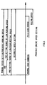
- Fig. 5 shows possible engine speed settings.
- the speed setting device which has been designed for internal combustion engines, especially diesel engines, in earth- working machines, comprises a system which is actuated in a specific manner and sets the diesel engine speed by means of a d.c. servomotor, the output shaft of which is fixedly connected to the control lever of the fuel injection pump of the diesel engine.
- a d.c. servomotor the output shaft of which is fixedly connected to the control lever of the fuel injection pump of the diesel engine.
- the system, and thus the speed of the diesel engine, is actuated by the manual control means 14 (levers, pedals etc.) of the machine, a push-button 16 on the control lever, and means 10 for manual setting of the engine speed.
- a so-called fuelmiser unit 3 is provided for changing to fixedly set resting speeds.
- the fuelmiser unit 3 can be manually connected or disconnected by means of a special switch 8.
- the diesel engine speed corresponds directly to the output signals from the speed determination unit 4 (i.e. the reference value corresponds to the actual working speed).
- the output diesel engine speed is indicated by a speed indicator 11. If required, the speed of the diesel engine M can be quickly changed manually by means of the push-button 16 on the control lever.
- the speed setting signals which determine the actual value to the d.c. servomotor 20 and which thus control the engine speed are as follows:
- Fig. 2 illustrates in more detail the function of the speed setting device for the diesel engine of the excavating machine.
- the device comprises a d.c. motor unit 1, a regulator unit 2, a fuelmiser unit 3 with a control unit 6, a speed determination unit 4 comprising a control unit ESC 5 (Engine Speed Control) and a signal converter 15.
- the d.c. motor unit 1 which has an output shaft including a gear and a sensor showing the rotation of the motor unit output shaft, is fixedly connected to the control lever 7 of the fuel injection pump of the diesel engine, said pump controlling the engine speed.
- the motor unit 1 sets the control lever 7 for engine speed control by means of the regulator unit 2, the input signal y (reference value) of which is determined by the speed determination unit 4 and the fuelmiser unit 3.
- the feedback value x of the regulator unit 2 corresponds to the angle of rotation 0 of the output shaft of the d.c. motor unit 1.
- the feedback value x is indicated by, for example, a rotary potentiometer of linear characteristic.
- an adjustable fixed stop which the lever 7 strikes in the event of a movement greater than the angular deflection of full speed.
- the output signal u (input signal to the fuelmiser unit 3) of the speed determination unit 4 preferably corresponds to the determined actual working speed of the diesel engine.
- the input signals of the speed determination unit 4 are an input signal from the manual speed setting device 10 and from the speed indicator 11 of the diesel engine, and a constant input signal from the setting means 9.
- the actual engine speed (low, variable or high) is indicated on, for example, a display in the driver's cabin.
- the output signal u corresponding to the actual working speed may be obtained for three predetermined working speeds.
- One of these working speeds, the variable working speed w 2 is manually and variably settable from the driver's seat.
- the variable working speed is determined by, for example, the hand-wheel for setting the accelerator 10 on the instrument panel. A complete clockwise turn of the hand-wheel gives a diesel engine working speed corresponding to full engine speed (so-called racing speed), and a complete counter-clockwise turn of the hand-wheel gives the lowest engine speed (idling speed).
- the low working speed (corresponding to the signal w ⁇ ) is obtained by direct signal conversion in the signal converter 15 of the variable speed (corresponding to the signal w 2 ) settable from the driver's seat.
- the high working speed (corresponding to signal w 3 ) is obtained by means of the setting means 9 (for example a potentiometer) which is set to a value corresponding to the racing speed of the diesel engine.
- the control unit 5, ESC (Engine Speed Control) of the speed determination unit 4 changes the actual working speed if, due to actuation of the manually settable speed setting device 10, the variable working speed exceeds a predetermined value of the low working speed (for example about 900 rpm), in the manner described below for the embodiment also illustrated in Fig. 3.
- a predetermined value of the low working speed for example about 900 rpm
- the actual reference value for setting the diesel engine speed is finally determined by the fuelmiser unit 3, the input signals of which are obtained, besides from the speed determination unit 4 (signal u), from sensors in the manual control means 14 of the working machine, the engine speed indicator 11 and the fuelmiser switch 8.
- the fuelmiser unit can be connected or disconnected by the switch 8. This implies that, when the fuelmiser unit is disconnected, its input and output signals merely consist of the output signal u of the speed determination unit 4, i.e. the fuelmiser unit does not, in the disconnected position, actuate the engine speed (the reference value corresponds to the actual working speed).
- the fuelmiser unit 3 is used for reducing the combustion engine speed from the actual working speed to the preset fixed resting speed, when the machine is not working, and for increasing the speed when the machine is working.
- the output signal y (the reference value of the regulator unit 2) of the fuelmiser unit 3 is then provided, by the control unit 6, with a signal corresponding to three alternative speed possibilities:
- the low and high resting speeds are set at suitable constant values by the setting means 13 and 12.
- the fuelmiser unit is inactive, i.e. its output signal corresponds directly to the output signal of the speed determination unit 4 (i.e. the reference value corresponds to the actual working speed) when
- the reference value y corresponds to the actual working speed (signal u).
- the reference value speed is changed in the manner indicated below and shown in Fig. 4.
- Fig. 5 illustrates the different speed setting possibilities available.
- the fixed speeds (low/high resting speed and low/high working speed) preset for the automatic speed setting are placed in an order and a dimension such that the speed setting can be effected in the most convenient manner by means of the above-mentioned automatic setting possibilities.
- speed setting in the present case may occur either manually or automatically, and that the automatic setting may occur between a settable lower speed which is higher than (for instance 300) the idling speed and an upper engine speed limited by the racing speed.
Landscapes
- Engineering & Computer Science (AREA)
- Chemical & Material Sciences (AREA)
- Combustion & Propulsion (AREA)
- Mechanical Engineering (AREA)
- General Engineering & Computer Science (AREA)
- Control Of Vehicle Engines Or Engines For Specific Uses (AREA)
- Electrical Control Of Air Or Fuel Supplied To Internal-Combustion Engine (AREA)
- Operation Control Of Excavators (AREA)
Claims (8)
Priority Applications (1)
| Application Number | Priority Date | Filing Date | Title |
|---|---|---|---|
| AT85905910T ATE42131T1 (de) | 1984-11-07 | 1985-11-06 | Vorrichtung zur geschwindigkeitsvorwahl eines erdbewegungsgeraetes mit innerem verbrennungsmotor, insbesondere dieselmotor. |
Applications Claiming Priority (2)
| Application Number | Priority Date | Filing Date | Title |
|---|---|---|---|
| SE8405565A SE454905B (sv) | 1984-11-07 | 1984-11-07 | Anordning for varvtalsinstellning av en motor i en arbetsmaskin |
| SE8405565 | 1984-11-07 |
Publications (2)
| Publication Number | Publication Date |
|---|---|
| EP0201582A1 EP0201582A1 (de) | 1986-11-20 |
| EP0201582B1 true EP0201582B1 (de) | 1989-04-12 |
Family
ID=20357644
Family Applications (1)
| Application Number | Title | Priority Date | Filing Date |
|---|---|---|---|
| EP85905910A Expired EP0201582B1 (de) | 1984-11-07 | 1985-11-06 | Vorrichtung zur geschwindigkeitsvorwahl eines erdbewegungsgerätes mit innerem verbrennungsmotor, insbesondere dieselmotor |
Country Status (8)
| Country | Link |
|---|---|
| US (1) | US4779591A (de) |
| EP (1) | EP0201582B1 (de) |
| DE (1) | DE3569407D1 (de) |
| DK (1) | DK159887C (de) |
| FI (1) | FI82294C (de) |
| NO (1) | NO162676C (de) |
| SE (1) | SE454905B (de) |
| WO (1) | WO1986002975A1 (de) |
Families Citing this family (23)
| Publication number | Priority date | Publication date | Assignee | Title |
|---|---|---|---|---|
| DE3609838A1 (de) * | 1986-03-22 | 1987-09-24 | Bosch Gmbh Robert | Stellzylinder |
| JP2831377B2 (ja) * | 1988-07-04 | 1998-12-02 | 日立建機株式会社 | 建設機械の原動機回転数制御装置 |
| JP2671137B2 (ja) * | 1988-08-31 | 1997-10-29 | スズキ株式会社 | 船外機エンジンのアイドリング回転速度制御システム |
| JPH05147460A (ja) * | 1991-11-27 | 1993-06-15 | Kubota Corp | 芝刈機のエンジン操作装置 |
| US5353762A (en) * | 1993-05-10 | 1994-10-11 | Briggs & Stratton Corporation | Modular automatic speed changing system |
| DE4414333A1 (de) * | 1994-04-25 | 1995-10-26 | Bayer Ag | Substituierte Pyridylpyrazole |
| US5445014A (en) * | 1994-08-12 | 1995-08-29 | Briggs & Stratton Corporation | Electronic engine load and revolution sensing device |
| US5586536A (en) * | 1995-11-29 | 1996-12-24 | Samsung Heavy Industries Co., Ltd. | Apparatus for and method of controlling engine RPM in hydraulic construction equipment |
| DE19733842C2 (de) * | 1997-08-05 | 2001-12-06 | Pietsch Max Kg Gmbh & Co | Verbrennungskraftmaschine mit einer Einrichtung zur Drehzahlansteuerung |
| US6286987B1 (en) | 1999-10-29 | 2001-09-11 | Cummins Engine Company, Inc. | System and method for controlling the speed of an engine providing power to a concrete mixing drum |
| US6694240B1 (en) | 2002-08-29 | 2004-02-17 | Caterpillar Inc | Control system for and method of operating a work machine |
| JP3971348B2 (ja) * | 2003-06-25 | 2007-09-05 | 日立建機株式会社 | 建設機械のエンジン制御装置 |
| JP4318170B2 (ja) * | 2003-08-25 | 2009-08-19 | 株式会社小松製作所 | 建設機械 |
| US7165530B2 (en) * | 2005-06-01 | 2007-01-23 | Caterpillar Inc | Method for controlling a variable-speed engine |
| FI119394B (fi) | 2005-12-02 | 2008-10-31 | Ponsse Oyj | Menetelmä metsäkoneen voimanlähteen ohjauksessa |
| US7343897B2 (en) * | 2006-03-22 | 2008-03-18 | Gm Global Technology Operations, Inc. | Engine control system with user-commanded engine speed adjustments in varying increments |
| US7900739B2 (en) | 2006-12-12 | 2011-03-08 | Cnh America Llc | Control system for a vehicle system with a continously variable transmission |
| US20090018745A1 (en) * | 2006-12-31 | 2009-01-15 | Caterpillar Inc | System and method for operating a machine |
| JP5121405B2 (ja) * | 2007-11-13 | 2013-01-16 | 株式会社小松製作所 | 建設機械のエンジン制御装置 |
| US8463527B2 (en) * | 2009-06-29 | 2013-06-11 | Superior Diesel, Inc. | Electronic diesel engine control device and method for automatic idle-down |
| JP5439083B2 (ja) * | 2009-07-31 | 2014-03-12 | 三菱重工業株式会社 | エンジンおよび該エンジンの回転数制御装置および回転数制御方法 |
| ITMO20110304A1 (it) * | 2011-11-28 | 2013-05-29 | Cnh Italia Spa | Engine control device for a work vehicle. |
| JP6001162B2 (ja) * | 2013-03-25 | 2016-10-05 | 日立建機株式会社 | 作業機械のエンジン回転数制御装置 |
Citations (2)
| Publication number | Priority date | Publication date | Assignee | Title |
|---|---|---|---|---|
| EP0166546A1 (de) * | 1984-05-31 | 1986-01-02 | Kabushiki Kaisha Komatsu Seisakusho | Vorrichtung zur Steuerung der Drehzahl eines auf einem Baufahrzeug angeordneten Motors |
| DE3307596C2 (de) * | 1983-01-04 | 1991-01-03 | Liebherr-Hydraulikbagger Gmbh, 7951 Kirchdorf | Vorrichtung zur Steuerung der Drehzahl eines Dieselmotors eines Hydraulikbaggers oder dergleichen |
Family Cites Families (6)
| Publication number | Priority date | Publication date | Assignee | Title |
|---|---|---|---|---|
| US2721072A (en) * | 1953-02-24 | 1955-10-18 | Caterpillar Tractor Co | Engine governor control for torque converter output shaft |
| US4373850A (en) * | 1980-02-14 | 1983-02-15 | Durham M E | Automatic fuel control system |
| US4372265A (en) * | 1980-07-14 | 1983-02-08 | Kasiewicz Stanley Joseph | Control circuit for engine speed governor with power take off |
| US4370961A (en) * | 1980-09-15 | 1983-02-01 | Derek Brown | Fuel rate control for internal combustion engines |
| US4422420A (en) * | 1981-09-24 | 1983-12-27 | Trw Inc. | Method and apparatus for fuel control in fuel injected internal combustion engines |
| JPS60157946U (ja) * | 1984-03-30 | 1985-10-21 | 株式会社小松製作所 | 油圧駆動車両のエンジン制御装置 |
-
1984
- 1984-11-07 SE SE8405565A patent/SE454905B/sv not_active IP Right Cessation
-
1985
- 1985-11-06 US US06/887,108 patent/US4779591A/en not_active Expired - Fee Related
- 1985-11-06 WO PCT/SE1985/000439 patent/WO1986002975A1/en not_active Ceased
- 1985-11-06 EP EP85905910A patent/EP0201582B1/de not_active Expired
- 1985-11-06 DE DE8585905910T patent/DE3569407D1/de not_active Expired
-
1986
- 1986-06-25 DK DK300786A patent/DK159887C/da active
- 1986-07-02 FI FI862819A patent/FI82294C/fi not_active IP Right Cessation
- 1986-07-04 NO NO862708A patent/NO162676C/no unknown
Patent Citations (2)
| Publication number | Priority date | Publication date | Assignee | Title |
|---|---|---|---|---|
| DE3307596C2 (de) * | 1983-01-04 | 1991-01-03 | Liebherr-Hydraulikbagger Gmbh, 7951 Kirchdorf | Vorrichtung zur Steuerung der Drehzahl eines Dieselmotors eines Hydraulikbaggers oder dergleichen |
| EP0166546A1 (de) * | 1984-05-31 | 1986-01-02 | Kabushiki Kaisha Komatsu Seisakusho | Vorrichtung zur Steuerung der Drehzahl eines auf einem Baufahrzeug angeordneten Motors |
Also Published As
| Publication number | Publication date |
|---|---|
| FI862819A0 (fi) | 1986-07-02 |
| US4779591A (en) | 1988-10-25 |
| NO862708D0 (no) | 1986-07-04 |
| NO162676B (no) | 1989-10-23 |
| SE454905B (sv) | 1988-06-06 |
| FI82294C (fi) | 1991-02-11 |
| DK159887B (da) | 1990-12-24 |
| DK159887C (da) | 1991-05-21 |
| DE3569407D1 (en) | 1989-05-18 |
| SE8405565D0 (sv) | 1984-11-07 |
| SE8405565L (sv) | 1986-05-08 |
| EP0201582A1 (de) | 1986-11-20 |
| NO862708L (no) | 1986-07-04 |
| FI82294B (fi) | 1990-10-31 |
| NO162676C (no) | 1990-01-31 |
| WO1986002975A1 (en) | 1986-05-22 |
| DK300786A (da) | 1986-08-21 |
| FI862819A7 (fi) | 1986-07-02 |
| DK300786D0 (da) | 1986-06-25 |
Similar Documents
| Publication | Publication Date | Title |
|---|---|---|
| EP0201582B1 (de) | Vorrichtung zur geschwindigkeitsvorwahl eines erdbewegungsgerätes mit innerem verbrennungsmotor, insbesondere dieselmotor | |
| EP0522171B1 (de) | Hydraulisches steuerungssystem für hydraulische erdbaumaschine | |
| EP0287670B1 (de) | Steuerregelungsvorrichtung für hydraulische konstruktionsmaschinen | |
| US5685377A (en) | Auto-return function for a bulldozer ripper | |
| EP1550803B1 (de) | Antriebsaggregatsteuerung einer baumaschine | |
| JPH07103593B2 (ja) | 積み込み作業車両の制御装置及び方法 | |
| US4774921A (en) | Method and system for controlling an engine | |
| US6073442A (en) | Apparatus and method for controlling a variable displacement pump | |
| US5479908A (en) | Engine speed control device | |
| JP2854899B2 (ja) | 油圧建設機械の駆動制御装置 | |
| KR100805990B1 (ko) | 유압구동제어장치 | |
| EP0159835A1 (de) | Verfahren und Vorrichtung zum Regeln eines Motors | |
| US5025770A (en) | Apparatus and engine to provide power to the apparatus | |
| JP2854898B2 (ja) | 油圧建設機械の駆動制御装置 | |
| JP2866178B2 (ja) | 作業車両の油圧駆動装置 | |
| JP3248549B2 (ja) | オートアクセル装置 | |
| JP3347847B2 (ja) | 作業機械の操作装置 | |
| KR950002127B1 (ko) | 굴삭기의 정지작업 제어방법 | |
| JP2805477B2 (ja) | 建設機械の動力制御方法及び装置 | |
| JPH0447400Y2 (de) | ||
| JPH03135844A (ja) | 油圧走行車両の原動機回転数制御装置 | |
| JPH0663251B2 (ja) | 油圧シヨベルの油圧制御装置 | |
| JPH02167935A (ja) | 油圧式建設機械の原動機回転数制御装置 | |
| JPH01113536A (ja) | 建設機械の原動機回転数制御装置 | |
| JPH0782767A (ja) | 建設機械のトレーラ積込モード切換装置 |
Legal Events
| Date | Code | Title | Description |
|---|---|---|---|
| PUAI | Public reference made under article 153(3) epc to a published international application that has entered the european phase |
Free format text: ORIGINAL CODE: 0009012 |
|
| 17P | Request for examination filed |
Effective date: 19860620 |
|
| AK | Designated contracting states |
Kind code of ref document: A1 Designated state(s): AT BE CH DE FR GB IT LI LU NL SE |
|
| 17Q | First examination report despatched |
Effective date: 19870529 |
|
| ITF | It: translation for a ep patent filed | ||
| GRAA | (expected) grant |
Free format text: ORIGINAL CODE: 0009210 |
|
| AK | Designated contracting states |
Kind code of ref document: B1 Designated state(s): AT BE CH DE FR GB IT LI LU NL SE |
|
| REF | Corresponds to: |
Ref document number: 42131 Country of ref document: AT Date of ref document: 19890415 Kind code of ref document: T |
|
| REF | Corresponds to: |
Ref document number: 3569407 Country of ref document: DE Date of ref document: 19890518 |
|
| ET | Fr: translation filed | ||
| PLBE | No opposition filed within time limit |
Free format text: ORIGINAL CODE: 0009261 |
|
| STAA | Information on the status of an ep patent application or granted ep patent |
Free format text: STATUS: NO OPPOSITION FILED WITHIN TIME LIMIT |
|
| 26N | No opposition filed | ||
| PGFP | Annual fee paid to national office [announced via postgrant information from national office to epo] |
Ref country code: LU Payment date: 19911107 Year of fee payment: 7 |
|
| PGFP | Annual fee paid to national office [announced via postgrant information from national office to epo] |
Ref country code: AT Payment date: 19911115 Year of fee payment: 7 |
|
| PGFP | Annual fee paid to national office [announced via postgrant information from national office to epo] |
Ref country code: CH Payment date: 19911125 Year of fee payment: 7 |
|
| ITTA | It: last paid annual fee | ||
| PGFP | Annual fee paid to national office [announced via postgrant information from national office to epo] |
Ref country code: NL Payment date: 19911130 Year of fee payment: 7 |
|
| EPTA | Lu: last paid annual fee | ||
| PG25 | Lapsed in a contracting state [announced via postgrant information from national office to epo] |
Ref country code: LU Free format text: LAPSE BECAUSE OF NON-PAYMENT OF DUE FEES Effective date: 19921106 Ref country code: AT Effective date: 19921106 |
|
| PG25 | Lapsed in a contracting state [announced via postgrant information from national office to epo] |
Ref country code: LI Effective date: 19921130 Ref country code: CH Effective date: 19921130 |
|
| PG25 | Lapsed in a contracting state [announced via postgrant information from national office to epo] |
Ref country code: NL Effective date: 19930601 |
|
| NLV4 | Nl: lapsed or anulled due to non-payment of the annual fee | ||
| REG | Reference to a national code |
Ref country code: CH Ref legal event code: PL |
|
| EAL | Se: european patent in force in sweden |
Ref document number: 85905910.7 |
|
| PGFP | Annual fee paid to national office [announced via postgrant information from national office to epo] |
Ref country code: GB Payment date: 19981014 Year of fee payment: 14 |
|
| PGFP | Annual fee paid to national office [announced via postgrant information from national office to epo] |
Ref country code: FR Payment date: 19981109 Year of fee payment: 14 |
|
| PGFP | Annual fee paid to national office [announced via postgrant information from national office to epo] |
Ref country code: BE Payment date: 19981110 Year of fee payment: 14 |
|
| PGFP | Annual fee paid to national office [announced via postgrant information from national office to epo] |
Ref country code: SE Payment date: 19981116 Year of fee payment: 14 |
|
| PGFP | Annual fee paid to national office [announced via postgrant information from national office to epo] |
Ref country code: DE Payment date: 19990129 Year of fee payment: 14 |
|
| PG25 | Lapsed in a contracting state [announced via postgrant information from national office to epo] |
Ref country code: GB Free format text: LAPSE BECAUSE OF NON-PAYMENT OF DUE FEES Effective date: 19991106 |
|
| PG25 | Lapsed in a contracting state [announced via postgrant information from national office to epo] |
Ref country code: SE Free format text: LAPSE BECAUSE OF NON-PAYMENT OF DUE FEES Effective date: 19991107 |
|
| PG25 | Lapsed in a contracting state [announced via postgrant information from national office to epo] |
Ref country code: BE Free format text: LAPSE BECAUSE OF NON-PAYMENT OF DUE FEES Effective date: 19991130 |
|
| BERE | Be: lapsed |
Owner name: AKERMANS VERKSTAD A.B. Effective date: 19991130 |
|
| GBPC | Gb: european patent ceased through non-payment of renewal fee |
Effective date: 19991106 |
|
| EUG | Se: european patent has lapsed |
Ref document number: 85905910.7 |
|
| PG25 | Lapsed in a contracting state [announced via postgrant information from national office to epo] |
Ref country code: FR Free format text: LAPSE BECAUSE OF NON-PAYMENT OF DUE FEES Effective date: 20000731 |
|
| PG25 | Lapsed in a contracting state [announced via postgrant information from national office to epo] |
Ref country code: DE Free format text: LAPSE BECAUSE OF NON-PAYMENT OF DUE FEES Effective date: 20000901 |
|
| REG | Reference to a national code |
Ref country code: FR Ref legal event code: ST |