EP0203368A1 - Procédé et dispositif pour la fabrication de laminés revêtus de cuivre - Google Patents
Procédé et dispositif pour la fabrication de laminés revêtus de cuivre Download PDFInfo
- Publication number
- EP0203368A1 EP0203368A1 EP86105597A EP86105597A EP0203368A1 EP 0203368 A1 EP0203368 A1 EP 0203368A1 EP 86105597 A EP86105597 A EP 86105597A EP 86105597 A EP86105597 A EP 86105597A EP 0203368 A1 EP0203368 A1 EP 0203368A1
- Authority
- EP
- European Patent Office
- Prior art keywords
- press
- belt
- copper
- reaction zone
- vertical
- Prior art date
- Legal status (The legal status is an assumption and is not a legal conclusion. Google has not performed a legal analysis and makes no representation as to the accuracy of the status listed.)
- Granted
Links
Images


Classifications
-
- B—PERFORMING OPERATIONS; TRANSPORTING
- B30—PRESSES
- B30B—PRESSES IN GENERAL
- B30B5/00—Presses characterised by the use of pressing means other than those mentioned in the preceding groups
- B30B5/04—Presses characterised by the use of pressing means other than those mentioned in the preceding groups wherein the pressing means is in the form of an endless band
- B30B5/06—Presses characterised by the use of pressing means other than those mentioned in the preceding groups wherein the pressing means is in the form of an endless band co-operating with another endless band
-
- B—PERFORMING OPERATIONS; TRANSPORTING
- B32—LAYERED PRODUCTS
- B32B—LAYERED PRODUCTS, i.e. PRODUCTS BUILT-UP OF STRATA OF FLAT OR NON-FLAT, e.g. CELLULAR OR HONEYCOMB, FORM
- B32B15/00—Layered products comprising a layer of metal
- B32B15/14—Layered products comprising a layer of metal next to a fibrous or filamentary layer
-
- B—PERFORMING OPERATIONS; TRANSPORTING
- B32—LAYERED PRODUCTS
- B32B—LAYERED PRODUCTS, i.e. PRODUCTS BUILT-UP OF STRATA OF FLAT OR NON-FLAT, e.g. CELLULAR OR HONEYCOMB, FORM
- B32B15/00—Layered products comprising a layer of metal
- B32B15/04—Layered products comprising a layer of metal comprising metal as the main or only constituent of a layer, which is next to another layer of the same or of a different material
-
- B—PERFORMING OPERATIONS; TRANSPORTING
- B32—LAYERED PRODUCTS
- B32B—LAYERED PRODUCTS, i.e. PRODUCTS BUILT-UP OF STRATA OF FLAT OR NON-FLAT, e.g. CELLULAR OR HONEYCOMB, FORM
- B32B15/00—Layered products comprising a layer of metal
- B32B15/20—Layered products comprising a layer of metal comprising aluminium or copper
-
- B—PERFORMING OPERATIONS; TRANSPORTING
- B32—LAYERED PRODUCTS
- B32B—LAYERED PRODUCTS, i.e. PRODUCTS BUILT-UP OF STRATA OF FLAT OR NON-FLAT, e.g. CELLULAR OR HONEYCOMB, FORM
- B32B37/00—Methods or apparatus for laminating, e.g. by curing or by ultrasonic bonding
- B32B37/10—Methods or apparatus for laminating, e.g. by curing or by ultrasonic bonding characterised by the pressing technique, e.g. using action of vacuum or fluid pressure
- B32B37/1027—Pressing using at least one press band
-
- B—PERFORMING OPERATIONS; TRANSPORTING
- B32—LAYERED PRODUCTS
- B32B—LAYERED PRODUCTS, i.e. PRODUCTS BUILT-UP OF STRATA OF FLAT OR NON-FLAT, e.g. CELLULAR OR HONEYCOMB, FORM
- B32B38/00—Ancillary operations in connection with laminating processes
-
- B—PERFORMING OPERATIONS; TRANSPORTING
- B32—LAYERED PRODUCTS
- B32B—LAYERED PRODUCTS, i.e. PRODUCTS BUILT-UP OF STRATA OF FLAT OR NON-FLAT, e.g. CELLULAR OR HONEYCOMB, FORM
- B32B5/00—Layered products characterised by the non- homogeneity or physical structure, i.e. comprising a fibrous, filamentary, particulate or foam layer; Layered products characterised by having a layer differing constitutionally or physically in different parts
- B32B5/22—Layered products characterised by the non- homogeneity or physical structure, i.e. comprising a fibrous, filamentary, particulate or foam layer; Layered products characterised by having a layer differing constitutionally or physically in different parts characterised by the presence of two or more layers which are next to each other and are fibrous, filamentary, formed of particles or foamed
- B32B5/24—Layered products characterised by the non- homogeneity or physical structure, i.e. comprising a fibrous, filamentary, particulate or foam layer; Layered products characterised by having a layer differing constitutionally or physically in different parts characterised by the presence of two or more layers which are next to each other and are fibrous, filamentary, formed of particles or foamed one layer being a fibrous or filamentary layer
- B32B5/26—Layered products characterised by the non- homogeneity or physical structure, i.e. comprising a fibrous, filamentary, particulate or foam layer; Layered products characterised by having a layer differing constitutionally or physically in different parts characterised by the presence of two or more layers which are next to each other and are fibrous, filamentary, formed of particles or foamed one layer being a fibrous or filamentary layer another layer next to it also being fibrous or filamentary
-
- C—CHEMISTRY; METALLURGY
- C25—ELECTROLYTIC OR ELECTROPHORETIC PROCESSES; APPARATUS THEREFOR
- C25D—PROCESSES FOR THE ELECTROLYTIC OR ELECTROPHORETIC PRODUCTION OF COATINGS; ELECTROFORMING; APPARATUS THEREFOR
- C25D7/00—Electroplating characterised by the article coated
- C25D7/06—Wires; Strips; Foils
- C25D7/0614—Strips or foils
-
- H—ELECTRICITY
- H05—ELECTRIC TECHNIQUES NOT OTHERWISE PROVIDED FOR
- H05K—PRINTED CIRCUITS; CASINGS OR CONSTRUCTIONAL DETAILS OF ELECTRIC APPARATUS; MANUFACTURE OF ASSEMBLAGES OF ELECTRICAL COMPONENTS
- H05K3/00—Apparatus or processes for manufacturing printed circuits
- H05K3/02—Apparatus or processes for manufacturing printed circuits in which the conductive material is applied to the surface of the insulating support and is thereafter removed from such areas of the surface which are not intended for current conducting or shielding
- H05K3/022—Processes for manufacturing precursors of printed circuits, i.e. copper-clad substrates
- H05K3/025—Processes for manufacturing precursors of printed circuits, i.e. copper-clad substrates by transfer of thin metal foil formed on a temporary carrier, e.g. peel-apart copper
-
- B—PERFORMING OPERATIONS; TRANSPORTING
- B32—LAYERED PRODUCTS
- B32B—LAYERED PRODUCTS, i.e. PRODUCTS BUILT-UP OF STRATA OF FLAT OR NON-FLAT, e.g. CELLULAR OR HONEYCOMB, FORM
- B32B2260/00—Layered product comprising an impregnated, embedded, or bonded layer wherein the layer comprises an impregnation, embedding, or binder material
- B32B2260/02—Composition of the impregnated, bonded or embedded layer
- B32B2260/021—Fibrous or filamentary layer
-
- B—PERFORMING OPERATIONS; TRANSPORTING
- B32—LAYERED PRODUCTS
- B32B—LAYERED PRODUCTS, i.e. PRODUCTS BUILT-UP OF STRATA OF FLAT OR NON-FLAT, e.g. CELLULAR OR HONEYCOMB, FORM
- B32B2260/00—Layered product comprising an impregnated, embedded, or bonded layer wherein the layer comprises an impregnation, embedding, or binder material
- B32B2260/04—Impregnation, embedding, or binder material
- B32B2260/046—Synthetic resin
-
- H—ELECTRICITY
- H05—ELECTRIC TECHNIQUES NOT OTHERWISE PROVIDED FOR
- H05K—PRINTED CIRCUITS; CASINGS OR CONSTRUCTIONAL DETAILS OF ELECTRIC APPARATUS; MANUFACTURE OF ASSEMBLAGES OF ELECTRICAL COMPONENTS
- H05K1/00—Printed circuits
- H05K1/02—Details
- H05K1/03—Use of materials for the substrate
- H05K1/0313—Organic insulating material
- H05K1/0353—Organic insulating material consisting of two or more materials, e.g. two or more polymers, polymer + filler, + reinforcement
- H05K1/0366—Organic insulating material consisting of two or more materials, e.g. two or more polymers, polymer + filler, + reinforcement reinforced, e.g. by fibres, fabrics
-
- H—ELECTRICITY
- H05—ELECTRIC TECHNIQUES NOT OTHERWISE PROVIDED FOR
- H05K—PRINTED CIRCUITS; CASINGS OR CONSTRUCTIONAL DETAILS OF ELECTRIC APPARATUS; MANUFACTURE OF ASSEMBLAGES OF ELECTRICAL COMPONENTS
- H05K2203/00—Indexing scheme relating to apparatus or processes for manufacturing printed circuits covered by H05K3/00
- H05K2203/01—Tools for processing; Objects used during processing
- H05K2203/0147—Carriers and holders
- H05K2203/0152—Temporary metallic carrier, e.g. for transferring material
-
- H—ELECTRICITY
- H05—ELECTRIC TECHNIQUES NOT OTHERWISE PROVIDED FOR
- H05K—PRINTED CIRCUITS; CASINGS OR CONSTRUCTIONAL DETAILS OF ELECTRIC APPARATUS; MANUFACTURE OF ASSEMBLAGES OF ELECTRICAL COMPONENTS
- H05K2203/00—Indexing scheme relating to apparatus or processes for manufacturing printed circuits covered by H05K3/00
- H05K2203/06—Lamination
- H05K2203/068—Features of the lamination press or of the lamination process, e.g. using special separator sheets
-
- H—ELECTRICITY
- H05—ELECTRIC TECHNIQUES NOT OTHERWISE PROVIDED FOR
- H05K—PRINTED CIRCUITS; CASINGS OR CONSTRUCTIONAL DETAILS OF ELECTRIC APPARATUS; MANUFACTURE OF ASSEMBLAGES OF ELECTRICAL COMPONENTS
- H05K2203/00—Indexing scheme relating to apparatus or processes for manufacturing printed circuits covered by H05K3/00
- H05K2203/07—Treatments involving liquids, e.g. plating, rinsing
- H05K2203/0703—Plating
- H05K2203/0726—Electroforming, i.e. electroplating on a metallic carrier thereby forming a self-supporting structure
-
- H—ELECTRICITY
- H05—ELECTRIC TECHNIQUES NOT OTHERWISE PROVIDED FOR
- H05K—PRINTED CIRCUITS; CASINGS OR CONSTRUCTIONAL DETAILS OF ELECTRIC APPARATUS; MANUFACTURE OF ASSEMBLAGES OF ELECTRICAL COMPONENTS
- H05K2203/00—Indexing scheme relating to apparatus or processes for manufacturing printed circuits covered by H05K3/00
- H05K2203/15—Position of the PCB during processing
- H05K2203/1545—Continuous processing, i.e. involving rolls moving a band-like or solid carrier along a continuous production path
-
- Y—GENERAL TAGGING OF NEW TECHNOLOGICAL DEVELOPMENTS; GENERAL TAGGING OF CROSS-SECTIONAL TECHNOLOGIES SPANNING OVER SEVERAL SECTIONS OF THE IPC; TECHNICAL SUBJECTS COVERED BY FORMER USPC CROSS-REFERENCE ART COLLECTIONS [XRACs] AND DIGESTS
- Y10—TECHNICAL SUBJECTS COVERED BY FORMER USPC
- Y10T—TECHNICAL SUBJECTS COVERED BY FORMER US CLASSIFICATION
- Y10T156/00—Adhesive bonding and miscellaneous chemical manufacture
- Y10T156/10—Methods of surface bonding and/or assembly therefor
- Y10T156/1052—Methods of surface bonding and/or assembly therefor with cutting, punching, tearing or severing
- Y10T156/1084—Methods of surface bonding and/or assembly therefor with cutting, punching, tearing or severing of continuous or running length bonded web
-
- Y—GENERAL TAGGING OF NEW TECHNOLOGICAL DEVELOPMENTS; GENERAL TAGGING OF CROSS-SECTIONAL TECHNOLOGIES SPANNING OVER SEVERAL SECTIONS OF THE IPC; TECHNICAL SUBJECTS COVERED BY FORMER USPC CROSS-REFERENCE ART COLLECTIONS [XRACs] AND DIGESTS
- Y10—TECHNICAL SUBJECTS COVERED BY FORMER USPC
- Y10T—TECHNICAL SUBJECTS COVERED BY FORMER US CLASSIFICATION
- Y10T156/00—Adhesive bonding and miscellaneous chemical manufacture
- Y10T156/15—Combined or convertible surface bonding means and/or assembly means
-
- Y—GENERAL TAGGING OF NEW TECHNOLOGICAL DEVELOPMENTS; GENERAL TAGGING OF CROSS-SECTIONAL TECHNOLOGIES SPANNING OVER SEVERAL SECTIONS OF THE IPC; TECHNICAL SUBJECTS COVERED BY FORMER USPC CROSS-REFERENCE ART COLLECTIONS [XRACs] AND DIGESTS
- Y10—TECHNICAL SUBJECTS COVERED BY FORMER USPC
- Y10T—TECHNICAL SUBJECTS COVERED BY FORMER US CLASSIFICATION
- Y10T156/00—Adhesive bonding and miscellaneous chemical manufacture
- Y10T156/19—Delaminating means
- Y10T156/195—Delaminating roller means
- Y10T156/1956—Roller pair delaminating means
Definitions
- the invention relates to a method for producing copper-clad laminates according to the preamble of claim 1 and an apparatus for performing this method.
- Such copper-clad laminates serve as the starting material for printed circuit boards and consist of a core of several layers of insulating material which is impregnated with a precondensed resin.
- phenolic resin-impregnated hard papers or epoxy resin-impregnated glass fiber fabrics the so-called prepreg.
- An electrolytically deposited copper foil of high purity is located on one or both surfaces of the core. The prepreg is pressed together with the copper foil under the action of heat to form the electrical laminate.
- the starting materials for the production of electrical laminates ie the resin-impregnated core layers and the copper foil, are available in rolls on rolls.
- the electrolytically deposited copper foils are produced with the help of a stainless steel drum, which dips part of the surface into a bath that contains copper ions in solution. In the bathroom there is an anode opposite the drum. The drum is switched as a cathode. Copper ions are then deposited on the part of the drum surface in the bath due to the electrical field located between the anode and cathode.
- the copper foil can be continuously removed from the uniformly rotating drum and wound up (see G. Leonida, Handbook of printed circuit design, manufacture, components & assembly, published in Electrochemical Publications Limited, 1981). Methods have also become known in which the copper film is not deposited on rotating drums but on strip-shaped belts (see DE-OS 28 39 481).
- the disadvantage of this known method is the two-stage process.
- the copper foils are electrolytically deposited as described, then rolled up and stored temporarily until they are pressed with the laminate. It is imperative that dust particles settle on the surface of the copper foil due to electrostatic attraction during storage and in particular also when the copper foil is being unwound in front of the double belt press.
- the dust particles that are on the surface of the copper foil that faces away from the laminate lead to inferior electrolaminates by being pressed into the surface of the copper foil during pressing and causing defects there.
- wipers are arranged in front of the double belt press to remove the dust before it enters the double belt press, it has been shown that this measure does not succeed in removing all the adhering dust.
- ultra-thin copper foils are desirable in and of itself, since both the etching time and the material consumption are significantly reduced when the electrical laminate is further processed into printed circuit boards.
- thick copper foil cannot be used due to the undercut of the conductor tracks and the use of ultra-thin foils is therefore essential.
- the present invention has for its object to provide a continuous process with surface pressure that avoids intermediate storage of the sensitive copper foil, the risk of defects due to dust, wrinkles or pore formation on the copper foil very much reduced and also the use of ultra-thin copper foils without the otherwise usual, expensive carrier allowed.
- the advantages that can be achieved with the invention consist in particular in the fact that the continuous process no longer proceeds in two stages, but in one stage. This eliminates the need for intermediate storage and additional handling of the copper foil and the associated risk of damage to the copper foil. Since the surface of the copper foil on the finished electrical laminate is continuously covered by the press belt until after pressing, no dust particles can settle on this surface, thus eliminating the risk of defects in the electrical laminate. Due to the direct deposition of the copper foil on the press belt, it receives the temperature of the press belt during the deposition, thereby avoiding wrinkles. With the advantageous use of the tampon electroplating method, the risk of micropores in the copper foil is completely eliminated due to the constant stress on the surface of the deposited foil. The thin copper foil is constantly carried by the press belt before pressing, which completely eliminates the need for an additional support for an ultra-thin copper foil. The method according to the invention increases the quality of the product and significantly reduces its cost.
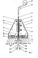
- the device shown in FIG. 1 is a vertically installed double belt press, so that its longitudinal axis is vertical.
- this double belt press 1 does not have four but six deflection drums 2, 3, 4, 5, 6, 7.
- three of these deflection drums 2, 3, 4 are arranged such that they sit at the corners of a right-angled triangle , the right angle being at the deflection drum 2.
- the press belts 8 and 9 are tensioned by means of hydraulic cylinders 10 and 11, which are fastened to the deflection drums 4 and 6, respectively.
- the deflection drums rotate in accordance with the arrows shown in FIG. 1, so that the press belts move in the direction of the arrow.
- a trough 12 is arranged below the horizontal catheter of the right-angled triangle in such a way that it extends along the press belt stretched between the deflection drums 2 and 3.
- the tub 12 is filled with an electrolyte 14, which consists of a copper sulfate solution.
- the tub 12 is filled to the extent that the outer surface of the press belt 8 is covered with the electrolyte 14.
- a plate 15 which in an appropriate distance from the part of the outer surface of the press belt which is immersed in the tub 12.
- This plate 15 has the same width as the press belt 8 and preferably a length which corresponds to the smallest distance between two peripheral points of the two deflection drums 2 and 3.
- the plate 16 is at a short distance from the press belt 8.
- a liquid metal 81 for example mercury (see also FIG. 4).
- the edges of the plate 16 are equipped with sliding seals 80 lying on the inner surface of the press belt, so that the liquid metal cannot escape from this intermediate space.
- the plates 15 and 16 are made of lead.
- the plate 15 located in the tub 12 is connected to the positive pole of a DC voltage source via a line with a sufficiently large cross section, so that it acts as an anode.
- the plate 16 attached to the inner surface of the press belt is connected to the negative pole of the same DC voltage source, so that that part of the press belt 8 which slides along the plate 16 and has electrical contact with the plate 16 via the liquid metal 81 made of mercury, than Cathode works.
- copper atoms are now deposited from the electrolyte 14 in the trough 12 on the location of the outer surface of the press belt 8 which acts as a cathode, opposite the anode 15.
- the layer thickness of the copper layer on the belt surface increases during the passage through the trough 12 and the layer thickness reaches its maximum value at the deflection drum 3 when it leaves the trough 12. This becomes direct according to the method according to the invention on the press belt galvanically deposited copper foil 17 is then transported with the press belt in the direction of the reaction zone 18 of the double belt press.
- the dimensioning of the DC voltage source which is usually represented by a mains transformer with a subsequent rectifier, is carried out according to the known laws of electrolysis.
- the temperature of the electrolyte in the tub 12 is constantly checked by means of temperature sensors mounted in the tub and kept constant by supplying appropriately tempered electrolytes.
- the used electrolyte is replaced at the same time by supplying it with fresh electrolyte, since the deposition of the copper ions on the strip surface reduces its concentration accordingly.
- both the temperature and the concentration of the electrolyte are constant over the entire deposition period.
- the plate 15, which is the anode In order to automatically keep the concentration of copper ions in the electrolyte constant, it is also possible to manufacture the plate 15, which is the anode, from copper and to use an acidic copper sulfate solution as the electrolyte liquid. During the electrolysis process, as many copper ions from the anode dissolve as copper ions from the electrolyte are reduced on the strip surface and are deposited there. The anode is of course used up and must be replaced from time to time with a new copper plate.
- the press belt 8 with the copper foil 17 electroplated on its surface moves at a uniform speed and leaves the electrolyte bath in the tub 12 at the deflection drum 3.
- the copper foil 17 is transported further to the deflection drum 4 with the press belt 8.
- the surface which is now on top can be treated for better adhesion of the copper foil 17 to the core layer.
- Such a treatment belonging to the prior art can be, for example, an etching of the copper foil surface or the deposition of strongly bud-forming brass coatings on the copper foil surface opposite the press belt.
- the copper foil 17 resting on the press belt 8 is deflected on the deflection drum 4 such that it now moves into the reaction zone 18 of the double belt press 1.
- webs 21a, 21b, 22a, 22b which consist of glass fiber fabric impregnated with epoxy resin, are also introduced into the reaction zone 18.
- These glass fiber webs form the core of the electrical laminate and are continuously drawn off from unwinding units 19a, 19b, 20a, 20b, which are located in the vicinity of the deflection drums 4 and 6.
- the core of the electrical laminate is formed by four layers of glass fiber webs. However, depending on the desired thickness and stability of the electrical laminate, more or fewer glass fiber webs can be used.
- all unwinding units can also be located at the deflection drum 4 or 6, or the unwinding units can be divided into the individual deflection drums according to the available space.
- the copper foils, glass fiber sheets as well as the electrical laminate are drawn exaggeratedly thick in relation to the double belt press for reasons of illustration.
- the second half of the press belt 25 consists of the Deflection drums 5, 6, 7 and the press belt 9, on the underside along the deflection drums 5 and 7 also a tub 13 is mounted. Analogous to the tub 12, this tub 13 contains an electrolyte liquid 14 and an anode 15. On the inside of the press belt 9 there is also a cathode 16 opposite the anode, the power supply being effected via liquid mercury, as explained further above, so that the Press belt 9 deposits a copper foil 23. This copper foil 23 is transported with the press belt 9 to the deflection drum 6 and deflected there into the reaction zone 18.
- the press belt unit 25 instead of on the press belt unit 24 as described.
- the reaction zone 18 there is the copper foil 17 on the press belt 8, on the surface facing away from the press belt 8 the impregnated glass fiber web 21a lies.
- the remaining glass fiber webs are in turn stacked on this glass fiber web 21a in the order 21b, 22b and 22a.
- the second surface of the web 22a lies against the press belt 9.
- a double-sided laminated electrical laminate is shown in FIG. 1, so that the web 22a lies against the surface of the copper foil 23.
- this copper foil 23 lies on the press belt 9 with the second surface. It should be noted in particular that if a surface treatment for improving the adhesion of the copper foil to the glass fiber core has taken place, the treated surface now rests on the respective glass fiber web 21a or 22a.
- the epoxy resin is cured by the pressure exerted on the material web in the reaction zone 18 and possibly with the additional use of heat, while the material web moves continuously through the reaction zone 18 and the glass fiber webs 21a, 21b, 22b, 22a are bonded to one another as well as to the adjacent copper foils 17, 23 connected to a solid unit, the so-called electrolaminate.
- the reaction zone can be divided into a heating zone which begins at the inlet into the double belt press at the deflection drums 4 and 6 and into a cooling zone which ends at the outlet at the deflection drums 2 and 5. This allows the material web to be cooled under pressure after the resin has hardened, which further improves the quality of the electrical laminate.
- the press belts 8 and 9 are deflected again and run into the tubs 12 and 13 of the electrolyte bath, where they are again coated with a copper foil.
- the now hardened electrolaminate separates, the surface of which consists of the copper foils 17 and 23 from the respective press belts 8 and 9. This separation generally presents no difficulties, since the copper galvanized onto the press belts made of stainless steel does not work well adheres to the surface of the press belt and in particular does not form a bond with this surface.
- the electrolaminate web 33 After the electrolaminate web 33 has left the double belt press, it is divided into individual plates according to the requirements by a cross-cutting saw which is not shown in FIG. 1. These copper-clad plates can be stacked in pallets for removal. Alternatively, if it is a flexible electrical laminate, the electrical laminate web 33 can be deflected with a deflection roller 32 and wound up into a roll in a winding unit 34.
- FIG. 2 A device for carrying out the method according to the invention, which operates in accordance with FIG. 1 and the above description, but in which the outlet and inlet are reversed, is shown in FIG. 2.
- the press belts 8 and 9 now move in the opposite direction according to the arrows .
- the copper foils 17 and 23 reach their maximum thicknesses when leaving the electrolyte bath at the deflection drums 2 and 5.
- the glass fiber webs impregnated with resin are now unwound from unwinding rollers 35a, 35b, 35c, 35d, which are located in the vicinity of the deflection drums 2 and 5, now run into the inlet of the double belt press at the deflection drums 2 and 5 and are pressed in the reaction zone 18 with the copper foils 17 and 23.
- the electrical laminate web 36 leaves the double belt press at the upper end at the deflection drums 4 and 6 and, if it is a flexible electrical laminate, is deflected with the deflection roller 37 so that it can be wound onto a roll in the winding unit 38.
- the electrical laminate web 36 can be cut behind the deflection drums 4 and 6 into panels of the desired size.
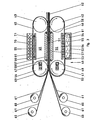
- FIG. 3 A further exemplary embodiment for carrying out the method according to the invention can be seen in FIG. 3.
- an ordinary double belt press as used for the production of decorative laminates.
- this double belt press is together with the unwind and open winding units set up rotated by 90 degrees to a longitudinal axis, so that the broad side of the press belts is now vertical, ie the double belt press is upright.
- This double belt press 40 has two adjacent press belt units 49, 50, in each of which two deflection drums 41, 42 and 43, 44 are mounted.
- An endless press belt 45, 46 is tensioned around two of these deflection drums, which in turn consists of a high-tensile stainless steel.
- the tension of the press belts 45, 46 is applied by hydraulic cylinders 47, 48, which are attached to the deflection rollers 41, 44.
- the deflection drums move in accordance with the arrows shown, so that the two press belts 45, 46 move in opposite directions.
- a trough 52 on the outer surface of the press belt 46, the height of which trough encompasses the entire broad side of the press belt.
- This tub 52 is equipped at the edges with seals 53 which slide against the press belt 46.
- the electrolyte liquid 54 which in turn consists of a copper sulfate solution.
- the tub 52 is further subjected to negative pressure, so that when the press belt 46 moves, supported by the seals 53, no electrolyte liquid emerges from the tub.
- the slide strips 56 are made of a metal and slidely touch the press belt 46.
- the support plate 55 is connected to the negative pole of the DC voltage source, so that the part of the press belt 46 located in the electrolyte 54 acts as a cathode via the slide strips 56.
- the tub 52 is made of a highly conductive metal and is connected to the positive pole of the DC voltage source, whereby the tub 52 itself is connected as an anode.
- a film 59 made of copper is deposited on the press belt strand located in the electrolyte, which is continuously moved through the trough 52, the maximum thickness of which is reached when the press belt strand has reached the 'delimitation of the trough 52 on the left in the drawing.
- the copper foil 59 lying on the press belt 46 is then deflected on the deflection drum 41 and introduced into the reaction zone 51.
- unwinding units 60 located in front of the double belt press with respect to the direction of movement of the material web, which, like the double belt press, are arranged vertically upright, webs 61 are continuously drawn off and pulled through the double belt press between the two copper foils 59, 69.
- These tracks 61 in turn consist of glass fiber fabric impregnated with epoxy resin.
- the number of unwinding units 60 depends on the desired structure of the core layer of the electrical laminate.
- the glass fiber webs are pressed together with the two copper foils under the action of heat to form an electrical laminate 62, which continuously leaves the double belt press 40 on the right-hand side in the drawing.
- FIG. 3 A further expedient embodiment of the method according to the invention is shown in FIG. 3 with the double belt unit 49 lying on the left in the forward direction.
- the galvanization of the copper foil 69 on the press belt 45 is carried out there by the tampon method known per se.
- a plate 70 which is connected to the positive pole of the direct voltage source and thus acts as an anode and is made of platinum, is covered with a sponge-like felt fabric 71.
- This felt fabric 71 has a certain width, so that the distance of the anode 70 from the press belt 45 is very precisely defined.
- the felt fabric 71 is impregnated with the electrolyte liquid consisting of copper sulfate.
- the press belt 45 is again connected as a cathode. Since a very small distance between anode 70 and press belt 45 is possible with the aid of the felt fabric, high current densities and thus high deposition rates of copper on the press belt surface 45 are obtained.
- the felt fabric 71 also serves as a kind of vessel for the electrolyte liquid. This advantageously eliminates the need for complex sealing devices which are necessary in the trough-shaped bath 52 in order to prevent the electrolyte liquid from flowing out.
- the electrolyte liquid can also be continuously moved through the felt fabric 71 with a pump.
- electrolyte liquids can also be used which are provided with certain additives in order to achieve an improved deposition of the copper. Such electrolyte liquids are known per se in the galvanizing process using the tampon process.
- the tampon method described can also be used for the double belt unit lying on the right in the forward direction in FIG. 3. If it appears desirable, the devices according to FIGS. 1 and 2 can also be provided with such a felt fabric 71 instead of the tub with the electrolyte liquid.
Landscapes
- Engineering & Computer Science (AREA)
- Chemical & Material Sciences (AREA)
- Manufacturing & Machinery (AREA)
- Microelectronics & Electronic Packaging (AREA)
- Electrochemistry (AREA)
- Materials Engineering (AREA)
- Metallurgy (AREA)
- Organic Chemistry (AREA)
- Mechanical Engineering (AREA)
- Chemical Kinetics & Catalysis (AREA)
- Physics & Mathematics (AREA)
- Fluid Mechanics (AREA)
- Laminated Bodies (AREA)
- Electroplating Methods And Accessories (AREA)
- Production Of Multi-Layered Print Wiring Board (AREA)
- Manufacturing Of Printed Wiring (AREA)
Applications Claiming Priority (2)
| Application Number | Priority Date | Filing Date | Title |
|---|---|---|---|
| DE19853515629 DE3515629A1 (de) | 1985-05-02 | 1985-05-02 | Verfahren und vorrichtung zur herstellung kupferkaschierter laminate |
| DE3515629 | 1985-05-02 |
Publications (2)
| Publication Number | Publication Date |
|---|---|
| EP0203368A1 true EP0203368A1 (fr) | 1986-12-03 |
| EP0203368B1 EP0203368B1 (fr) | 1989-03-08 |
Family
ID=6269529
Family Applications (1)
| Application Number | Title | Priority Date | Filing Date |
|---|---|---|---|
| EP86105597A Expired EP0203368B1 (fr) | 1985-05-02 | 1986-04-23 | Procédé et dispositif pour la fabrication de laminés revêtus de cuivre |
Country Status (6)
| Country | Link |
|---|---|
| US (1) | US4687528A (fr) |
| EP (1) | EP0203368B1 (fr) |
| JP (1) | JPS61255858A (fr) |
| CN (1) | CN1019369B (fr) |
| DE (2) | DE3515629A1 (fr) |
| SU (2) | SU1438636A3 (fr) |
Cited By (4)
| Publication number | Priority date | Publication date | Assignee | Title |
|---|---|---|---|---|
| WO1988006647A1 (fr) * | 1987-03-02 | 1988-09-07 | M & T Laminates Limited | Production de materiau dielectrique cuivre |
| DE3811467A1 (de) * | 1988-04-06 | 1989-10-19 | Siempelkamp Gmbh & Co | Verfahren und anlage zur kontinuierlichen herstellung von bahnfoermigem basismaterial fuer leiterplatten |
| EP0363794A3 (fr) * | 1988-10-14 | 1991-10-16 | Kurt Held | Procédé et appareil pour fabriquer en continu des laminates |
| US5662761A (en) * | 1992-07-21 | 1997-09-02 | Amp-Akzo Lin Lam Vof | Method of manufacturing a UD-reinforced PWB laminate |
Families Citing this family (29)
| Publication number | Priority date | Publication date | Assignee | Title |
|---|---|---|---|---|
| JPS63136695A (ja) * | 1986-11-28 | 1988-06-08 | 三菱電機株式会社 | シ−ルド板の製造方法および装置 |
| JPS63285998A (ja) * | 1987-05-18 | 1988-11-22 | Mitsubishi Electric Corp | 多層基板の製造方法および装置 |
| JPS63285997A (ja) * | 1987-05-18 | 1988-11-22 | Mitsubishi Electric Corp | 多層基板の製造方法および装置 |
| US5149394A (en) * | 1988-10-14 | 1992-09-22 | Kurt Held | Method and apparatus for continuously fabricating laminates |
| US5034087A (en) * | 1989-11-16 | 1991-07-23 | Doboy Packaging Machinery, Inc. | Self-adjusting heat seal bar |
| DE4118249C2 (de) * | 1991-06-04 | 1994-10-27 | Guenther Dr Schwarz | Verfahren und Vorrichtung zur Massenkonservierung von Archivalien |
| US5806177A (en) * | 1995-10-31 | 1998-09-15 | Sumitomo Bakelite Company Limited | Process for producing multilayer printed circuit board |
| DE19541406C1 (de) * | 1995-11-07 | 1996-10-17 | Held Kurt | Verfahren und Vorrichtung zur Herstellung von harzimprägnierten Schichtpreßstoffen |
| US7056403B2 (en) * | 1999-01-12 | 2006-06-06 | Hunter Douglas Inc. | Apparatus for producing non-woven fabric |
| US6883213B2 (en) * | 1999-01-12 | 2005-04-26 | Hunter Douglas Inc. | Apparatus for producing non-woven fabric |
| CA2355710C (fr) * | 1999-01-12 | 2008-03-18 | Hunter Douglas Inc. | Etoffe non tissee et procede et appareil de fabrication d'une telle etoffe |
| US7090743B2 (en) * | 1999-09-20 | 2006-08-15 | Hunter Douglas Inc. | Pressure laminator apparatus |
| US6805771B1 (en) | 1999-09-20 | 2004-10-19 | Hunter Douglas Industries B.V. | Pressure laminator apparatus and non woven fabric formed thereby |
| CA2384370C (fr) * | 1999-09-20 | 2009-03-10 | Hunter Douglas Inc. | Appareil de contrecollage a pression et tissu non tisse forme au moyen de cet appareil |
| US6926055B1 (en) | 1999-09-20 | 2005-08-09 | Hunter Douglas Inc. | Non-woven composite fabric and method and apparatus for manufacturing same |
| JP2001138437A (ja) * | 1999-11-17 | 2001-05-22 | Sumitomo Bakelite Co Ltd | 積層板の製造方法 |
| EP1302293B1 (fr) * | 2000-07-14 | 2007-11-14 | Mitsubishi Rayon Co., Ltd. | Procede de production d'une feuille en matiere carbonnee |
| US7017244B2 (en) * | 2002-06-03 | 2006-03-28 | Hunter Douglas Inc. | Beam winding apparatus |
| US7695486B2 (en) * | 2002-10-02 | 2010-04-13 | Linda Dixon | Intradermal color introducing needle device, and apparatus and method involving the same |
| CN1813084B (zh) * | 2003-06-27 | 2010-05-05 | 京瓷株式会社 | 金属镀膜的形成方法、电子部件制造方法及镀膜形成装置 |
| US8246808B2 (en) * | 2008-08-08 | 2012-08-21 | GM Global Technology Operations LLC | Selective electrochemical deposition of conductive coatings on fuel cell bipolar plates |
| JP5602152B2 (ja) * | 2009-01-07 | 2014-10-08 | スウェディッシュ バイオミメティックス 3000 リミテッド | 二重移動相の装置および方法 |
| US20110318590A1 (en) * | 2009-03-25 | 2011-12-29 | Du Pont-Mitsui Polychemicals Co., Ltd. | Metal layer-attached film for electronic component, method for producing the film, and use thereof |
| JPWO2013191026A1 (ja) * | 2012-06-22 | 2016-05-26 | 株式会社シンク・ラボラトリー | プリント回路基板の製造装置並びに製造方法 |
| CN103668374B (zh) * | 2013-12-19 | 2016-05-18 | 湖南永盛新材料股份有限公司 | 一种宽幅不锈钢带单面镀铜的方法及电镀槽 |
| CN108187965B (zh) * | 2018-02-11 | 2023-03-21 | 刘希文 | 一种输送带式面压力覆膜涂装工艺及装置 |
| US10960615B2 (en) * | 2018-11-13 | 2021-03-30 | The Boeing Company | System and method for laminating a composite laminate along a continuous loop lamination path |
| CN109591426B (zh) * | 2018-12-05 | 2019-09-13 | 广东嘉元科技股份有限公司 | 一种覆铜箔板的制备装置 |
| CN113696498B (zh) * | 2021-08-25 | 2023-03-31 | 开显工业自动化科技(苏州)有限公司 | 无限延续的带式复合材料挤压成型装置 |
Citations (4)
| Publication number | Priority date | Publication date | Assignee | Title |
|---|---|---|---|---|
| DE1704785A1 (de) * | 1967-12-30 | 1971-05-27 | Kalle Ag | Verfahren zum Herstellen eines Verbundmaterials mit einer Metallschicht |
| US4399183A (en) * | 1979-12-27 | 1983-08-16 | E. I. Du Pont De Nemours And Company | Web-supported membrane |
| DE3212152A1 (de) * | 1982-04-01 | 1983-10-13 | Doduco KG Dr. Eugen Dürrwächter, 7530 Pforzheim | Vorrichtung zum selektiven galvanischen beschichten eines bandes |
| EP0120192A2 (fr) * | 1983-03-01 | 1984-10-03 | Kurt Held | Procédé de fabrication continue d'électrolaminés revêtus de cuivre et dispositif pour l'exécution dudit procédé |
Family Cites Families (10)
| Publication number | Priority date | Publication date | Assignee | Title |
|---|---|---|---|---|
| US3043728A (en) * | 1958-03-17 | 1962-07-10 | Nat Res Corp | Apparatus and process for metallic vapor coating |
| GB1226199A (fr) * | 1967-12-30 | 1971-03-24 | ||
| US3857681A (en) * | 1971-08-03 | 1974-12-31 | Yates Industries | Copper foil treatment and products produced therefrom |
| US3984598A (en) * | 1974-02-08 | 1976-10-05 | Universal Oil Products Company | Metal-clad laminates |
| FR2390517A1 (fr) * | 1977-05-10 | 1978-12-08 | Coppertron Sa | Installation pour l'electro-production de cuivre en feuilles destinees a etre appliquees en particulier sur des materiaux dielectriques |
| DE2820196A1 (de) * | 1978-05-09 | 1979-11-15 | Califoil Inc | Verfahren zur herstellung einer duennen kupferfolie |
| DE3023827C2 (de) * | 1980-06-25 | 1985-11-21 | Siemens AG, 1000 Berlin und 8000 München | Anlage zum galvanischen Abscheiden von Aluminium |
| US4587166A (en) * | 1983-02-16 | 1986-05-06 | Ampex Corporation | Plated magnetic recording material and process for making same |
| DE3342678C2 (de) * | 1983-11-25 | 1995-08-31 | Held Kurt | Verfahren und Vorrichtung zur kontinuierlichen Herstellung metallkaschierter Laminate |
| DE3413434A1 (de) * | 1984-04-10 | 1985-10-17 | Dielektra GmbH, 5000 Köln | Verfahren zum kontinuierlichen herstellen von kupferkaschiertem basismaterial fuer leiterplatten |
-
1985
- 1985-05-02 DE DE19853515629 patent/DE3515629A1/de not_active Withdrawn
-
1986
- 1986-04-23 EP EP86105597A patent/EP0203368B1/fr not_active Expired
- 1986-04-23 DE DE8686105597T patent/DE3662240D1/de not_active Expired
- 1986-04-24 US US06/855,791 patent/US4687528A/en not_active Expired - Fee Related
- 1986-04-28 SU SU864027358A patent/SU1438636A3/ru active
- 1986-04-30 CN CN86103035A patent/CN1019369B/zh not_active Expired
- 1986-05-01 JP JP61099521A patent/JPS61255858A/ja active Granted
-
1987
- 1987-03-22 SU SU874202615A patent/SU1542430A3/ru active
Patent Citations (4)
| Publication number | Priority date | Publication date | Assignee | Title |
|---|---|---|---|---|
| DE1704785A1 (de) * | 1967-12-30 | 1971-05-27 | Kalle Ag | Verfahren zum Herstellen eines Verbundmaterials mit einer Metallschicht |
| US4399183A (en) * | 1979-12-27 | 1983-08-16 | E. I. Du Pont De Nemours And Company | Web-supported membrane |
| DE3212152A1 (de) * | 1982-04-01 | 1983-10-13 | Doduco KG Dr. Eugen Dürrwächter, 7530 Pforzheim | Vorrichtung zum selektiven galvanischen beschichten eines bandes |
| EP0120192A2 (fr) * | 1983-03-01 | 1984-10-03 | Kurt Held | Procédé de fabrication continue d'électrolaminés revêtus de cuivre et dispositif pour l'exécution dudit procédé |
Cited By (4)
| Publication number | Priority date | Publication date | Assignee | Title |
|---|---|---|---|---|
| WO1988006647A1 (fr) * | 1987-03-02 | 1988-09-07 | M & T Laminates Limited | Production de materiau dielectrique cuivre |
| DE3811467A1 (de) * | 1988-04-06 | 1989-10-19 | Siempelkamp Gmbh & Co | Verfahren und anlage zur kontinuierlichen herstellung von bahnfoermigem basismaterial fuer leiterplatten |
| EP0363794A3 (fr) * | 1988-10-14 | 1991-10-16 | Kurt Held | Procédé et appareil pour fabriquer en continu des laminates |
| US5662761A (en) * | 1992-07-21 | 1997-09-02 | Amp-Akzo Lin Lam Vof | Method of manufacturing a UD-reinforced PWB laminate |
Also Published As
| Publication number | Publication date |
|---|---|
| SU1542430A3 (ru) | 1990-02-07 |
| JPH032661B2 (fr) | 1991-01-16 |
| US4687528A (en) | 1987-08-18 |
| CN86103035A (zh) | 1986-11-12 |
| JPS61255858A (ja) | 1986-11-13 |
| DE3662240D1 (en) | 1989-04-13 |
| SU1438636A3 (ru) | 1988-11-15 |
| EP0203368B1 (fr) | 1989-03-08 |
| CN1019369B (zh) | 1992-12-09 |
| DE3515629A1 (de) | 1986-11-06 |
Similar Documents
| Publication | Publication Date | Title |
|---|---|---|
| EP0203368B1 (fr) | Procédé et dispositif pour la fabrication de laminés revêtus de cuivre | |
| DE1621184C3 (de) | Vorrichtung zum einseitigen Galvanisieren von Metallbändern | |
| WO2010034300A2 (fr) | Écran de sérigraphie | |
| EP0120192A2 (fr) | Procédé de fabrication continue d'électrolaminés revêtus de cuivre et dispositif pour l'exécution dudit procédé | |
| EP1051886A2 (fr) | Dispositif de traitement electrolytique de carte de circuits et de feuilles conductrices | |
| DE2758031A1 (de) | Verfahren zum herstellen von metallfolien | |
| DE3149519A1 (de) | Verfahren und vorrichtung zur galvanisierung /verzinkung) von metallband | |
| DE19717489B4 (de) | Anordnung zur elektrogalvanischen Metallbeschichtung eines Bandes | |
| DE2108787C2 (de) | Vorrichtung zur Galvanisierung von Blechen mit einer mit einem kathodischen Kontaktring versehenen Trommel | |
| DE3100634C2 (de) | Vorrichtung zum Galvanisieren eines Bandes aus elektrisch leitendem Material | |
| DE2615326C2 (de) | Verfahren und Einrichtung zum selektiven kontinuierlichen oder intermittierenden Galvanisieren eines rechteckigen flächigen Materials | |
| DE19727132C2 (de) | Verfahren und Vorrichtung zur Herstellung einer Prägestruktur auf einem der Oberflächenformung von Preßlaminaten dienenden Prägewerkzeug | |
| DE3320078A1 (de) | Anordnung und verfahren zur herstellung von geschichteten einheiten | |
| EP0030334A1 (fr) | Appareil d'électrolyse pour le renforcement galvanique de feuilles en matière synthétique sous forme de bandes préalablement revêtues d'une couche conductrice | |
| DE1521306B2 (de) | Verfahren zum elektrolytischen oder chemischen aufbringen von elektrischen leitungszuegen | |
| DE3036444A1 (de) | Verfahren und vorrichtung zum elektrisch leitenden verbinden von bahnenmaterial | |
| DE19633797B4 (de) | Vorrichtung zum Galvanisieren von elektronischen Leiterplatten oder dergleichen | |
| WO1994003655B1 (fr) | Procede et dispositif de traitement electrolytique d'articles particulierement plats | |
| DE3423734C1 (de) | Anlage zur elektrolytischen Oberflaechenbeschichtung eines Metallbandes,insbesondere zur Verzinkung von Stahlband | |
| DE1621626B1 (de) | Verfahren und vorrichtung zur kontinuierlichen oberflaechenbehandlung der kantenbereiche von metallblech | |
| EP0859071B1 (fr) | Procédé de revêtement sélectif galvanique d'éléments de contact électrique | |
| DE69032213T2 (de) | Harz-Laminat, Verfahren und Vorrichtung zum Herstellen dessen und Verfahren zum Herstellen einer Harzschicht für das Harz-Laminat. | |
| DE2009118A1 (de) | Verfahren und Vorrichtung zur kontinuierlichen Elektroplattierung einer Seite eines Stahlbandes | |
| DE1222558B (de) | Verfahren und Vorrichtung zur Herstellung gedruckter, elektrischer Schaltungsmuster | |
| WO2007140949A1 (fr) | Dispositif de déposition galvanique de surfaces et système de galvanisation |
Legal Events
| Date | Code | Title | Description |
|---|---|---|---|
| PUAI | Public reference made under article 153(3) epc to a published international application that has entered the european phase |
Free format text: ORIGINAL CODE: 0009012 |
|
| AK | Designated contracting states |
Kind code of ref document: A1 Designated state(s): DE FR GB IT SE |
|
| 17P | Request for examination filed |
Effective date: 19861219 |
|
| 17Q | First examination report despatched |
Effective date: 19871111 |
|
| ITF | It: translation for a ep patent filed | ||
| GRAA | (expected) grant |
Free format text: ORIGINAL CODE: 0009210 |
|
| AK | Designated contracting states |
Kind code of ref document: B1 Designated state(s): DE FR GB IT SE |
|
| GBT | Gb: translation of ep patent filed (gb section 77(6)(a)/1977) | ||
| REF | Corresponds to: |
Ref document number: 3662240 Country of ref document: DE Date of ref document: 19890413 |
|
| ET | Fr: translation filed | ||
| PLBE | No opposition filed within time limit |
Free format text: ORIGINAL CODE: 0009261 |
|
| STAA | Information on the status of an ep patent application or granted ep patent |
Free format text: STATUS: NO OPPOSITION FILED WITHIN TIME LIMIT |
|
| 26N | No opposition filed | ||
| ITTA | It: last paid annual fee | ||
| EAL | Se: european patent in force in sweden |
Ref document number: 86105597.8 |
|
| PGFP | Annual fee paid to national office [announced via postgrant information from national office to epo] |
Ref country code: FR Payment date: 19950428 Year of fee payment: 10 |
|
| PGFP | Annual fee paid to national office [announced via postgrant information from national office to epo] |
Ref country code: DE Payment date: 19951222 Year of fee payment: 10 |
|
| PGFP | Annual fee paid to national office [announced via postgrant information from national office to epo] |
Ref country code: SE Payment date: 19960314 Year of fee payment: 11 |
|
| PGFP | Annual fee paid to national office [announced via postgrant information from national office to epo] |
Ref country code: GB Payment date: 19961023 Year of fee payment: 11 |
|
| PG25 | Lapsed in a contracting state [announced via postgrant information from national office to epo] |
Ref country code: FR Effective date: 19961227 |
|
| PG25 | Lapsed in a contracting state [announced via postgrant information from national office to epo] |
Ref country code: DE Effective date: 19970101 |
|
| REG | Reference to a national code |
Ref country code: FR Ref legal event code: ST |
|
| PG25 | Lapsed in a contracting state [announced via postgrant information from national office to epo] |
Ref country code: GB Effective date: 19970423 |
|
| PG25 | Lapsed in a contracting state [announced via postgrant information from national office to epo] |
Ref country code: SE Effective date: 19970424 |
|
| GBPC | Gb: european patent ceased through non-payment of renewal fee |
Effective date: 19970423 |
|
| EUG | Se: european patent has lapsed |
Ref document number: 86105597.8 |
|
| PG25 | Lapsed in a contracting state [announced via postgrant information from national office to epo] |
Ref country code: IT Free format text: LAPSE BECAUSE OF NON-PAYMENT OF DUE FEES;WARNING: LAPSES OF ITALIAN PATENTS WITH EFFECTIVE DATE BEFORE 2007 MAY HAVE OCCURRED AT ANY TIME BEFORE 2007. THE CORRECT EFFECTIVE DATE MAY BE DIFFERENT FROM THE ONE RECORDED. Effective date: 20050423 |