EP0203553A2 - Système de pinces - Google Patents
Système de pinces Download PDFInfo
- Publication number
- EP0203553A2 EP0203553A2 EP86107067A EP86107067A EP0203553A2 EP 0203553 A2 EP0203553 A2 EP 0203553A2 EP 86107067 A EP86107067 A EP 86107067A EP 86107067 A EP86107067 A EP 86107067A EP 0203553 A2 EP0203553 A2 EP 0203553A2
- Authority
- EP
- European Patent Office
- Prior art keywords
- gripper
- spindle
- gas pressure
- grippers
- pressure spring
- Prior art date
- Legal status (The legal status is an assumption and is not a legal conclusion. Google has not performed a legal analysis and makes no representation as to the accuracy of the status listed.)
- Granted
Links
- 230000006835 compression Effects 0.000 description 7
- 238000007906 compression Methods 0.000 description 7
- 239000011324 bead Substances 0.000 description 3
- 238000009434 installation Methods 0.000 description 2
- CYJRNFFLTBEQSQ-UHFFFAOYSA-N 8-(3-methyl-1-benzothiophen-5-yl)-N-(4-methylsulfonylpyridin-3-yl)quinoxalin-6-amine Chemical compound CS(=O)(=O)C1=C(C=NC=C1)NC=1C=C2N=CC=NC2=C(C=1)C=1C=CC2=C(C(=CS2)C)C=1 CYJRNFFLTBEQSQ-UHFFFAOYSA-N 0.000 description 1
- 238000010276 construction Methods 0.000 description 1
Images


Classifications
-
- B—PERFORMING OPERATIONS; TRANSPORTING
- B41—PRINTING; LINING MACHINES; TYPEWRITERS; STAMPS
- B41F—PRINTING MACHINES OR PRESSES
- B41F21/00—Devices for conveying sheets through printing apparatus or machines
- B41F21/10—Combinations of transfer drums and grippers
- B41F21/104—Gripper details
Definitions
- the invention relates to a gripper system for preferably a cylinder of a sheet-fed rotary printing press, according to the preamble of patent claim 1.
- One-piece grippers for cylinders or drums of rotary printing machines have become known, for example, from DE-PS 27 25 035.
- This patent describes a one-piece gripper with a gripper tip, which is fastened directly to a pivotable gripper spindle by means of a screw and is pivotably supported thereon.
- a compression spring is arranged, the abutment of which lies on the gripper spindle and the point of engagement on the gripper finger.
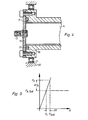
- the gripper contact force F A is set depending on the deflection path X. Due to the torsion of the grippers wave, caused by the sum of the individual gripper bearing forces, and by inaccuracies when setting the individual grippers, the deflection paths X of the individual grippers are of course different. Desirable are now gripper "with a spring characteristic" very “stiff" and for a short fürfederungsweg X 1 merges into a horizontal line at a desired contact force F A target (X 1), that is, the gripper pad force F A independently of the deflection paths X would (Fig. 9 dash-dotted line).
- the invention has for its object to provide a gripper system for sheet-fed rotary printing machines, in which the spring characteristic of the gripper can be designed such that the characteristic curve is relatively steep for a short deflection path, i.e. the contact force increases and, after reaching a certain deflection path, the characteristic curve changes into a horizontal or in the vicinity of a horizontal, so that the contact force is approximately independent of the deflection path.
- a gripper spindle 1 consists of a tube 2.
- the gripper spindle 1 is mounted in a known manner at its two ends in bearings 5 in a pit of a rubber or transfer cylinder 10.
- a roller lever At one end of the gripper spindle 1, to drive this, a roller lever, not shown, is attached.
- the gripper spindle 1 At the locations of the gripper spindle 1, at which the gripper 3 to be attached, the gripper spindle 1 is provided over a circumference of, for example 110 0, each with a recess. 4
- the recess 4 ends in an extension 6.
- the extension 6 is wider than a length of a hook bearing shaft 7 of the gripper 3. This extension 6 allows the hook 3 in a simple manner from the gripper spindle 1 Removing b zw.
- V-shaped receptacles 8 are incorporated in the interior of the tube 2.
- Receptacles 8 and gripper bearing shaft 7 each form a bearing point in which the gripper 3 can be pivoted.
- An elastic, pressure-resistant hose 9 is arranged within the tube 2 of the gripper spindle 1.
- An outer diameter D of the tube 9 corresponds approximately to an inner diameter d of the tube 2.
- the tube 2 can be sealed at both ends 11 in the manner as shown in FIG. 4, for example.
- a cover 12 is screwed onto both ends 11 of the tube 2.
- the covers 12 each have a check valve 13 which open into an interior 14 of the hose 9.
- the ends 11 of the tube 2 are each provided with a circular recess 16.
- These punctures 16 serve as receptacles for an annular bead 17 at both ends of the hose 9.
- the cover 12 When the cover 12 is screwed on, the bead 17 is pressed against a wall of the puncture 16 and thus the ends of the hose 9 are sealed.
- the hose 9 is filled with compressed air via the check valve 13 and acts in the gas-filled state as a prestressed gas pressure spring.
- a gripper foot 33 of the gripper 3 reaches through the recess 4 and is supported on the hose 9 (gas pressure spring 9).
- Each of the one-piece grippers 3 has an on adjusting device 18 or 19 for changing an angular position c6 of a gripper tip 23 of the gripper 3 around the gripper bearing shaft 7.
- the gripper tip 23 can hereby be adjusted to the associated gripper support 15.
- the setting device 18 consists of a threaded bore 21 and a grub screw 22 which can be screwed into and out of it.
- the threaded bore 21 is located near a gripper tip 23.
- the adjusting device 19 for the gripper 3 consists of a threaded bore 24 in the tube 2, a screw 26 screwed into the threaded bore 24, a spring cup 27 placed on the screw 26 and a compression spring 29 supported between the tube 2 and a spring cup base 28
- Wall 31 of the spring cup 27 is supported on one end 32 of the gripper foot 33 of the gripper 3.
- the remaining part of the wall 31 has a non-positive connection with the tube 2 only via the compression spring 29 (FIG. 7).
- the hose 9 sealed at both ends within the tube 2 thus forms a gas pressure spring in which the deformation path is small in relation to the enclosed gas volume.
- gas springs With frictionless isentropic (adiabatic) compression, gas springs almost ideally show the behavior desired for grippers.
Landscapes
- Supply, Installation And Extraction Of Printed Sheets Or Plates (AREA)
- Feeding Of Articles By Means Other Than Belts Or Rollers (AREA)
- Manipulator (AREA)
Applications Claiming Priority (2)
| Application Number | Priority Date | Filing Date | Title |
|---|---|---|---|
| DE19853519293 DE3519293A1 (de) | 1985-05-30 | 1985-05-30 | Greifersystem |
| DE3519293 | 1985-05-30 |
Publications (3)
| Publication Number | Publication Date |
|---|---|
| EP0203553A2 true EP0203553A2 (fr) | 1986-12-03 |
| EP0203553A3 EP0203553A3 (en) | 1987-09-23 |
| EP0203553B1 EP0203553B1 (fr) | 1989-08-09 |
Family
ID=6271944
Family Applications (1)
| Application Number | Title | Priority Date | Filing Date |
|---|---|---|---|
| EP86107067A Expired EP0203553B1 (fr) | 1985-05-30 | 1986-05-23 | Système de pinces |
Country Status (3)
| Country | Link |
|---|---|
| EP (1) | EP0203553B1 (fr) |
| JP (1) | JPH07102678B2 (fr) |
| DE (2) | DE3519293A1 (fr) |
Cited By (1)
| Publication number | Priority date | Publication date | Assignee | Title |
|---|---|---|---|---|
| US5395151A (en) * | 1992-12-02 | 1995-03-07 | Ferag Ag | Gripper for a conveying device for conveying single-sheet or multi-sheet printed products |
Families Citing this family (2)
| Publication number | Priority date | Publication date | Assignee | Title |
|---|---|---|---|---|
| DE4221929C2 (de) * | 1992-07-03 | 1997-11-20 | Heidelberger Druckmasch Ag | Greifersteuerung für Bogengreifer an einem bogenführenden Zylinder oder dergleichen in einer Druckmaschine |
| DE19927695A1 (de) | 1998-07-06 | 2000-01-13 | Heidelberger Druckmasch Ag | Greifer für einen bogentransportierenden Zylinder oder Trommel einer Rotationsdruckmaschine |
Family Cites Families (4)
| Publication number | Priority date | Publication date | Assignee | Title |
|---|---|---|---|---|
| DE1100043B (de) * | 1958-08-15 | 1961-02-23 | Leipziger Buchbindereimaschine | Greifer an Druck- und Buchbinderei-Maschinen zum Erfassen und Festhalten von Bogen aus Papier, Pappe oder aehnlichem Material |
| JPS52105009A (en) * | 1976-02-26 | 1977-09-03 | Komori Printing Mach | Paper gripper for sheet printing machine |
| DE2725035C3 (de) * | 1977-06-03 | 1979-11-22 | Koenig & Bauer Ag, 8700 Wuerzburg | Greifer |
| ES230780Y (es) * | 1977-08-26 | 1978-07-01 | Conjunto de pinza y abrazadera para el transporte de laminasen maquinas litograficas. |
-
1985
- 1985-05-30 DE DE19853519293 patent/DE3519293A1/de active Granted
-
1986
- 1986-05-23 EP EP86107067A patent/EP0203553B1/fr not_active Expired
- 1986-05-23 DE DE8686107067T patent/DE3664882D1/de not_active Expired
- 1986-05-30 JP JP61123831A patent/JPH07102678B2/ja not_active Expired - Lifetime
Cited By (2)
| Publication number | Priority date | Publication date | Assignee | Title |
|---|---|---|---|---|
| US5395151A (en) * | 1992-12-02 | 1995-03-07 | Ferag Ag | Gripper for a conveying device for conveying single-sheet or multi-sheet printed products |
| AU658770B2 (en) * | 1992-12-02 | 1995-04-27 | Ferag Ag | Gripper for a conveying device for conveying single-sheet or multi-sheet printing products |
Also Published As
| Publication number | Publication date |
|---|---|
| DE3519293C2 (fr) | 1989-04-20 |
| EP0203553B1 (fr) | 1989-08-09 |
| EP0203553A3 (en) | 1987-09-23 |
| DE3519293A1 (de) | 1986-12-04 |
| JPS61277454A (ja) | 1986-12-08 |
| DE3664882D1 (en) | 1989-09-14 |
| JPH07102678B2 (ja) | 1995-11-08 |
Similar Documents
| Publication | Publication Date | Title |
|---|---|---|
| DE1182914B (de) | Rollmembrankolben | |
| DE3410046A1 (de) | Abstreifvorrichtung fuer foerderbaender | |
| DE3023747C2 (de) | Atemgerät | |
| DE2821100C2 (de) | Regelventil mit Handantrieb | |
| DE2824361C2 (de) | Vorrichtung zum Konstanthalten der in einem Kabel oder dergleichen herrschenden Zugspannung | |
| DE2841116C2 (de) | Vorrichtung zum Abziehen von Hülsen, Lagerringen o.dgl. | |
| EP0118699A2 (fr) | Dispositif de positionnement | |
| EP0203553A2 (fr) | Système de pinces | |
| DE2152302C3 (de) | Stoßfänger für Docks, Schiffsanlegestellen od.dgl | |
| DE2846138B2 (de) | Umformer zur Umformung der Drehbewegung einer Welle in eine geradlinige Bewegung eines Betätigungsgliedes | |
| EP0483535B1 (fr) | Dispositif de serrage pour fixer de fins revêtements sur des cylindres transportant des feuilles dans des rotatives d'impression pour feuilles | |
| DE3608470A1 (de) | Umfuehrtrommel fuer den bogentransport in einer druckmaschine | |
| DE60005496T2 (de) | Differentialsperre | |
| EP0240877A1 (fr) | Recouvrement télescopique | |
| DE2542122B2 (de) | Mechanische Hilfslöseeinrichtung für Federspeicher- oder Kombizylinder | |
| EP0377857B1 (fr) | Dispositif électrique de sécurité d'un système d'accouplement de tambour de transfert de feuilles dans une presse | |
| DE3018022A1 (de) | Bremsvorrichtung fuer fahrzeuge | |
| DE69000285T2 (de) | Klemmvorrichtung. | |
| DE8515787U1 (de) | Greifersystem | |
| DE3614096A1 (de) | Vorrichtung zur momentuebertragung und zur begrenzung des uebertragenen momentes | |
| EP0013746A2 (fr) | Dispositif de serrage de pièces à usiner | |
| DE1293789B (de) | Ventilanordnung einer Kolbenbrennkraftmaschine mit einer Drehvorrichtung | |
| DE2547918B2 (de) | Regelstabantrieb für einen Kernreaktor | |
| DE2221513A1 (de) | Steuerhebelanordnung | |
| DE3914453A1 (de) | Mast fuer ein segelbrett |
Legal Events
| Date | Code | Title | Description |
|---|---|---|---|
| PUAI | Public reference made under article 153(3) epc to a published international application that has entered the european phase |
Free format text: ORIGINAL CODE: 0009012 |
|
| AK | Designated contracting states |
Kind code of ref document: A2 Designated state(s): DE FR GB IT SE |
|
| PUAL | Search report despatched |
Free format text: ORIGINAL CODE: 0009013 |
|
| AK | Designated contracting states |
Kind code of ref document: A3 Designated state(s): DE FR GB IT SE |
|
| 17P | Request for examination filed |
Effective date: 19871202 |
|
| 17Q | First examination report despatched |
Effective date: 19880526 |
|
| ITF | It: translation for a ep patent filed | ||
| GRAA | (expected) grant |
Free format text: ORIGINAL CODE: 0009210 |
|
| AK | Designated contracting states |
Kind code of ref document: B1 Designated state(s): DE FR GB IT SE |
|
| GBT | Gb: translation of ep patent filed (gb section 77(6)(a)/1977) | ||
| ET | Fr: translation filed | ||
| REF | Corresponds to: |
Ref document number: 3664882 Country of ref document: DE Date of ref document: 19890914 |
|
| PLBE | No opposition filed within time limit |
Free format text: ORIGINAL CODE: 0009261 |
|
| STAA | Information on the status of an ep patent application or granted ep patent |
Free format text: STATUS: NO OPPOSITION FILED WITHIN TIME LIMIT |
|
| 26N | No opposition filed | ||
| ITTA | It: last paid annual fee | ||
| EAL | Se: european patent in force in sweden |
Ref document number: 86107067.0 |
|
| PGFP | Annual fee paid to national office [announced via postgrant information from national office to epo] |
Ref country code: GB Payment date: 20010425 Year of fee payment: 16 |
|
| PGFP | Annual fee paid to national office [announced via postgrant information from national office to epo] |
Ref country code: FR Payment date: 20010518 Year of fee payment: 16 |
|
| PGFP | Annual fee paid to national office [announced via postgrant information from national office to epo] |
Ref country code: SE Payment date: 20010521 Year of fee payment: 16 |
|
| REG | Reference to a national code |
Ref country code: GB Ref legal event code: IF02 |
|
| PG25 | Lapsed in a contracting state [announced via postgrant information from national office to epo] |
Ref country code: GB Free format text: LAPSE BECAUSE OF NON-PAYMENT OF DUE FEES Effective date: 20020523 |
|
| PG25 | Lapsed in a contracting state [announced via postgrant information from national office to epo] |
Ref country code: SE Free format text: LAPSE BECAUSE OF NON-PAYMENT OF DUE FEES Effective date: 20020524 |
|
| EUG | Se: european patent has lapsed | ||
| GBPC | Gb: european patent ceased through non-payment of renewal fee |
Effective date: 20020523 |
|
| PG25 | Lapsed in a contracting state [announced via postgrant information from national office to epo] |
Ref country code: FR Free format text: LAPSE BECAUSE OF NON-PAYMENT OF DUE FEES Effective date: 20030131 |
|
| REG | Reference to a national code |
Ref country code: FR Ref legal event code: ST |
|
| PGFP | Annual fee paid to national office [announced via postgrant information from national office to epo] |
Ref country code: DE Payment date: 20030625 Year of fee payment: 18 |
|
| PG25 | Lapsed in a contracting state [announced via postgrant information from national office to epo] |
Ref country code: DE Free format text: LAPSE BECAUSE OF NON-PAYMENT OF DUE FEES Effective date: 20041201 |
|
| PG25 | Lapsed in a contracting state [announced via postgrant information from national office to epo] |
Ref country code: IT Free format text: LAPSE BECAUSE OF NON-PAYMENT OF DUE FEES;WARNING: LAPSES OF ITALIAN PATENTS WITH EFFECTIVE DATE BEFORE 2007 MAY HAVE OCCURRED AT ANY TIME BEFORE 2007. THE CORRECT EFFECTIVE DATE MAY BE DIFFERENT FROM THE ONE RECORDED. Effective date: 20050523 |