EP0205295A2 - Lubrification de laminoirs - Google Patents
Lubrification de laminoirs Download PDFInfo
- Publication number
- EP0205295A2 EP0205295A2 EP86304173A EP86304173A EP0205295A2 EP 0205295 A2 EP0205295 A2 EP 0205295A2 EP 86304173 A EP86304173 A EP 86304173A EP 86304173 A EP86304173 A EP 86304173A EP 0205295 A2 EP0205295 A2 EP 0205295A2
- Authority
- EP
- European Patent Office
- Prior art keywords
- rolls
- casing
- casings
- work
- roll
- Prior art date
- Legal status (The legal status is an assumption and is not a legal conclusion. Google has not performed a legal analysis and makes no representation as to the accuracy of the status listed.)
- Granted
Links
Images


Classifications
-
- B—PERFORMING OPERATIONS; TRANSPORTING
- B21—MECHANICAL METAL-WORKING WITHOUT ESSENTIALLY REMOVING MATERIAL; PUNCHING METAL
- B21B—ROLLING OF METAL
- B21B27/00—Rolls, roll alloys or roll fabrication; Lubricating, cooling or heating rolls while in use
- B21B27/06—Lubricating, cooling or heating rolls
- B21B27/10—Lubricating, cooling or heating rolls externally
-
- B—PERFORMING OPERATIONS; TRANSPORTING
- B21—MECHANICAL METAL-WORKING WITHOUT ESSENTIALLY REMOVING MATERIAL; PUNCHING METAL
- B21B—ROLLING OF METAL
- B21B3/00—Rolling materials of special alloys so far as the composition of the alloy requires or permits special rolling methods or sequences ; Rolling of aluminium, copper, zinc or other non-ferrous metals
- B21B2003/001—Aluminium or its alloys
Definitions
- This invention relates to rolling mills and methods of rolling metal, such as aluminium, in rolling mills.
- the coolant is usually water or is water-based. It has been customary to also include a rolling lubricant, for example, in the form of an oil-water emulsion.
- European Patent Specification No. 0160381A proposes a method of rolling metal in a rolling mill in which liquid coolant is applied to a roll or rolls on the ingoing side of the mill within a casing or casings, unwanted egress of coolant from the casing or casings being prevented by the use of contact seals engaging the roll or rolls.
- Rolling lubricant is independently applied to the work and/or the work rolls at the ingoing side of the mill outside the casing or casings.
- contact seals are used, which are more effective than air seals in preventing escape of moisture. Their use is possible because the rolls at the ingoing side of the mill are at a reasonably low temperature and because the contact seals are lubricated by the coolant. No coolant mist is generated and there is no escape route for the mist even if it were generated.
- the contact seals further act as cleaners for the rolls and prevent particulate material being carried into the roll gap by the rolls and damaging the rolls and the work.
- rolling lubricant is applied separately from the coolant at the ingoing side of the mill and outside the casing or casings.
- the separate application of rolling lubricant is essential because of the effectiveness of the contact seals but, apart from that, it enables the lubricant to be distributed more evenly, makes possible better control of the lubricant, and can result in better efficiency of lubricant usage.
- the contact seals are subject to wear and will require repositioning or replacement when worn in order to ensure effective operation.
- Shut down of the rolling mill for seal maintenance is clearly economically undesirable.
- the positioning of the seals in close proximity to the mill rolls makes maintenance access difficult.
- Regular roll maintenance for example, for regrinding of the work rolls, is an accepted feature of rolling mill operation, whereby the rolls are withdrawn sideways from the mill to a roll change car for transfer to a regrinding or storage station and fresh rolls are then moved into position to define the roll gap.
- the present invention seeks to synchronise seal maintenance with roll maintenance.
- a rolling mill comprising a plurality of rolls, means for directing liquid coolant on to the rolls at the ingoing side of the mill and a casing or casings which during operation enclose the directing means and have contact seals engaging the rolls to prevent unwanted egress of coolant from the casing or casings on to work entering the mill, wherein the means for directing liquid coolant on to the rolls are mounted on one or more backing supports, sealing means are provided between the casing or casings and the backing support or supports and the casing or casings are mounted for withdrawal from the mill for maintenance purposes independently of said one or more backing supports.
- said one or more backing supports are movable away from the mill rolls during maintenance.
- the backing supports may suitably be mounted on a bridle assembly for control of the work tension upstream of the roll gap.
- the bridle assembly may be mounted so that it can be pivoted away from the rolls during maintenance.
- the mill comprises a pair of work rolls each having an associated back-up roll, a separate casing being provided for each work roll having contact seals adapted to engage the work roll and its associated back-up roll.
- the casing or casings are preferably carried by chocks for the work rolls.
- the sealing means preferably comprises an inflatable peripheral seal between the or each backing support and the or each casing.
- the contact seals may be provided with inflatable means for urging the seals into contact with the rolls.
- a preferred form of face seal contacting a roll substantially across its entire width comprises a wiper strip of resilient material held in parallel with a support block of low friction material biased towards the adjacent roll.
- a method of rolling metal in a rolling mill having a plurality of rolls including a pair of work rolls comprises directing liquid coolant from coolant supply means mounted on one or more backing supports on to the rolls at the ingoing side of the mill during operation within a casing or casings having contact seals engaging the rolls to prevent unwanted egress of coolant on to the work entering the mill and wherein said work rolls are periodically withdrawn for maintenance purposes together with said casing or casings independently of said one or more backing supports.
- the rolling mill has upper and lower work rolls 2 and 3, respectively, and upper and lower back-up rolls 4 and 5, respectively.
- the work for example, aluminium strip, is indicated at 6, the direction of movement of the work being from left to right.
- Coolant is applied to the rolls at the ingoing side of the mill, i.e. at the left-hand side of the rolls in the drawings.
- Spray bars 8 are in use located, respectively, above and below the pass line and extend the full length of the rolls and have at closely spaced intervals sets of spray nozzles 9 directed at the work rolls, the back-up rolls and the nips therebetween.
- the spray bars are preferably as described in European Patent Specifications Nos. 0041863B and 0153532A.
- Each spray bar 8 is in use located within an enclosed sealing chamber 10, as shown in Figure 2, which contains totally the coolant discharged by the nozzles 9 and prohibits the egress of coolant on to the strip 6. Used coolant is withdrawn from the chambers via discharge outlet 11, upper and lower chambers being interconnected for this purpose by any suitable means.
- the sealing chambers 10 are each in two separable parts, i.e. an open-backed casing 12 and a backing frame 13.
- Backing frames 13 are interconnected and mounted on the side of a bridle assembly 14, best seen in Figure 1, for control of work tension upstream of the roll gap by means of a series of rollers 15.
- Bridle assembly 14 is pivoted at 7 to a suitable fixed support, so that, during roll maintenance, it can be pivoted away from the rolls by operation of piston and cylinder arrangement 20, as shown in Figure 1.
- Backing frames 13 provide a mounting for the spray bars 8 so that, during rolling, as shown in Figure 2, the bars 8 are enclosed within the sealing chambers 10.
- the open-backed casings 12 are mounted on mounting plates 16 attached to work roll chocks 17 and 18 for the upper and lower work rolls 2 and 3, respectively.
- the open rear face of each casing 12 has a frame 19 against which can seal an inflatable ring seal 21 positioned around the facing periphery 22 of backing frame 13.
- Hydraulically operated piston and cylinder arrangements 23 are each pivotally connected to mounting plates 16 at one end 24 while the other end is attached to the frame 19 of casing 12.
- Springs 30 are connected between plate 16 and casing 12.
- casings 12 are urged towards the roll nips between the rolls 2 and 4 and the rolls 3 and 5 and can accommodate to varying roll diameters and varying nip conformations.
- the inflation of ring seal 21 ensures that the sealing chamber is sealed to prevent egress of coolant while the rolling mill is in operation.
- Casings 12 are provided with face seals 25 and end seals 26. These seals may be constructed as described in co-pending Application No. [85144] and, if required, nip sealing blocks may be incorporated to seal into the nips between the back-up and work rolls.
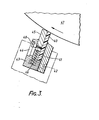
- FIG. 3 An alternative form of face seal is shown in Figure 3.
- Conventional seals comprise a block of suitable seal material, such as polyurethane, removably mounted in a holder from which the seal projects.
- the seal tends to wear along one edge and can be remounted up to four times in the holder to redistribute the wear.
- back-up rolls which normally have a poorer surface finish than that required for work rolls, cause increased wear on the seals.
- a seal which lasts up to 300 hours against a work roll may require replacement after only 30 hours against a back-up roll.
- the seal shown in Figure 3 seeks to extend the wear life of the seal.
- the seal is in the form of an elongate strip 40, for example, of polyurethane, adhered to a metal strip 41 and clamped by screw 42 within a holder 43.
- Holder 4S is apertured to accommodate a seal support block 45, for example, of graphite, loaded by spring 46 so that it will extend from the holder 43 but adjust to the length of strip 40 as the roll, a portion of which is shown at 47, rotates.
- support block 45 will continue to support the block and adjust itself to project to the same extent as strip 40 from holder 43.
- Block 45 can also be adjusted in relation to spring 46 by location screw 48 housed in slot 44.
- the back-up rolls 4 and 5 are moved vertically away from the work rolls to the positions shown in Figure 1.
- the bridle assembly 14 with backing frame 13 and spray bars 8 is pivoted away from the mill.
- the work roll chocks 17 and 18 are then moved transversely, via wheels 28 supported on rails 27 within the mill, on to a roll change car (not shown) provided with rails in alignment with rails 27.
- a suitable transfer device is provided to move the work rolls out through the window provided in the mill housing on to the roll change car.
- the car carries a replacement roll stack, complete with seal casings 12, mounted on further sets of rails which can then be moved into the mill using the transfer device.
- the removed rolls, with the associated casings 12 can then be transferred to, for example, a roll grinding shop. Any necessary maintenance work on the seals can be carried out at the same time.
Landscapes
- Engineering & Computer Science (AREA)
- Mechanical Engineering (AREA)
- Rolls And Other Rotary Bodies (AREA)
- Metal Rolling (AREA)
Priority Applications (1)
| Application Number | Priority Date | Filing Date | Title |
|---|---|---|---|
| AT86304173T ATE58851T1 (de) | 1985-06-10 | 1986-06-02 | Schmierung von walzwerken. |
Applications Claiming Priority (4)
| Application Number | Priority Date | Filing Date | Title |
|---|---|---|---|
| GB858514597A GB8514597D0 (en) | 1985-06-10 | 1985-06-10 | Lubrication of rolling mills |
| GB8514597 | 1985-06-10 | ||
| GB858514599A GB8514599D0 (en) | 1985-06-10 | 1985-06-10 | Lubrication of rolling mills |
| GB8514599 | 1985-06-10 |
Publications (3)
| Publication Number | Publication Date |
|---|---|
| EP0205295A2 true EP0205295A2 (fr) | 1986-12-17 |
| EP0205295A3 EP0205295A3 (en) | 1987-10-07 |
| EP0205295B1 EP0205295B1 (fr) | 1990-12-05 |
Family
ID=26289349
Family Applications (1)
| Application Number | Title | Priority Date | Filing Date |
|---|---|---|---|
| EP86304173A Expired EP0205295B1 (fr) | 1985-06-10 | 1986-06-02 | Lubrification de laminoirs |
Country Status (3)
| Country | Link |
|---|---|
| US (1) | US4709568A (fr) |
| EP (1) | EP0205295B1 (fr) |
| DE (1) | DE3675985D1 (fr) |
Cited By (5)
| Publication number | Priority date | Publication date | Assignee | Title |
|---|---|---|---|---|
| EP0349840A3 (fr) * | 1988-07-06 | 1990-10-10 | Sms Schloemann-Siemag Aktiengesellschaft | Laminoir pour la production des matières à laminer |
| WO1991005621A1 (fr) * | 1989-10-10 | 1991-05-02 | Alcan International Limited | Appareil de confinement du refrigerant pour laminoirs |
| WO1993008938A1 (fr) * | 1991-11-01 | 1993-05-13 | Davy Mckee (Poole) Limited | Ameliorations apportees a des laminoirs |
| WO1998048956A1 (fr) * | 1997-04-30 | 1998-11-05 | Travhydro Plastics Et Isolants Mecanises | Dispositif racleur pour laminoir |
| EP3251762A1 (fr) * | 2016-06-02 | 2017-12-06 | Primetals Technologies Austria GmbH | Dispositif de lubrification pour l'application d'un lubrifiant lors du laminage d'un produit de laminage |
Families Citing this family (5)
| Publication number | Priority date | Publication date | Assignee | Title |
|---|---|---|---|---|
| US5524465A (en) * | 1991-03-29 | 1996-06-11 | Hitachi, Ltd. | Work rolls crossing type mill, rolling system and rolling method |
| DE10043281B4 (de) * | 2000-04-08 | 2004-04-15 | ACHENBACH BUSCHHüTTEN GMBH | Walzenkühl- und/oder Schmiervorrichtung für Kaltbandwalzwerke, insbesondere Feinband- und Folienwalzwerke |
| DE102006049161A1 (de) * | 2006-10-18 | 2008-04-24 | Sms Demag Ag | Walzgerüst mit Stütz- und/oder Arbeitswalzen zum Walzen von Blechen oder Bändern |
| WO2012146536A1 (fr) * | 2011-04-29 | 2012-11-01 | Oelheld Gmbh | Procédé et dispositif de lubrification d'une bande de matériau |
| EP2881186A1 (fr) * | 2013-12-09 | 2015-06-10 | Linde Aktiengesellschaft | Procédé et appareil pour isoler le froid dans un équipement cryogénique |
Family Cites Families (13)
| Publication number | Priority date | Publication date | Assignee | Title |
|---|---|---|---|---|
| US1781798A (en) * | 1928-10-24 | 1930-11-18 | John D Williams | Roll heater |
| US2107541A (en) * | 1934-09-06 | 1938-02-08 | American Rolling Mill Co | Wiping device for rolling mill rolls |
| CA985533A (en) * | 1973-09-14 | 1976-03-16 | Dominion Engineering Works | Entry and delivery guides for cold rolling mills |
| GB1433301A (en) * | 1974-02-19 | 1976-04-28 | Loewy Robertson Eng Co Ltd | Tension bridle for a rolling mill |
| GB1511247A (en) * | 1974-06-11 | 1978-05-17 | Alcan Res & Dev | Method and apparatus for cooling the rolls of rolling mills |
| ATE1622T1 (de) * | 1978-11-03 | 1982-10-15 | Davy-Loewy Limited | Tandem walzwerk. |
| US4272976A (en) * | 1979-06-05 | 1981-06-16 | Mesta Machine Company | Hot strip rolling mill stand |
| DE3168285D1 (en) * | 1980-06-11 | 1985-02-28 | Davy Mckee Poole | Spray unit for rolling mill |
| FR2497828B1 (fr) * | 1981-01-09 | 1986-07-25 | Usinor | Dispositif d'etancheite pour machine de traitement de toles |
| EP0114535A1 (fr) * | 1983-01-21 | 1984-08-01 | Wean United, Inc. | Dispositif pour éliminer un liquide d'une bande en cours de laminage et procédé d'élimination correspondant |
| GB8404387D0 (en) * | 1984-02-20 | 1984-03-28 | Davy Mckee Poole | Applying liquid for rolling mill |
| GB2156255A (en) * | 1984-03-23 | 1985-10-09 | Davy Mckee | Rolling mill |
| GB8514598D0 (en) * | 1985-06-10 | 1985-07-10 | Davy Mckee Poole | Lubrication of rolling mills |
-
1986
- 1986-06-02 DE DE8686304173T patent/DE3675985D1/de not_active Expired - Lifetime
- 1986-06-02 EP EP86304173A patent/EP0205295B1/fr not_active Expired
- 1986-06-10 US US06/872,394 patent/US4709568A/en not_active Expired - Fee Related
Cited By (8)
| Publication number | Priority date | Publication date | Assignee | Title |
|---|---|---|---|---|
| EP0349840A3 (fr) * | 1988-07-06 | 1990-10-10 | Sms Schloemann-Siemag Aktiengesellschaft | Laminoir pour la production des matières à laminer |
| WO1991005621A1 (fr) * | 1989-10-10 | 1991-05-02 | Alcan International Limited | Appareil de confinement du refrigerant pour laminoirs |
| WO1993008938A1 (fr) * | 1991-11-01 | 1993-05-13 | Davy Mckee (Poole) Limited | Ameliorations apportees a des laminoirs |
| WO1998048956A1 (fr) * | 1997-04-30 | 1998-11-05 | Travhydro Plastics Et Isolants Mecanises | Dispositif racleur pour laminoir |
| EP3251762A1 (fr) * | 2016-06-02 | 2017-12-06 | Primetals Technologies Austria GmbH | Dispositif de lubrification pour l'application d'un lubrifiant lors du laminage d'un produit de laminage |
| WO2017207622A1 (fr) * | 2016-06-02 | 2017-12-07 | Primetals Technologies Austria GmbH | Dispositif de lubrification destiné à appliquer un lubrifiant lors du laminage d'un produit à laminer |
| RU2704877C1 (ru) * | 2016-06-02 | 2019-10-31 | Прайметалз Текнолоджиз Аустриа ГмбХ | Смазочное устройство для нанесения смазочного средства при прокатке прокатываемого материала |
| US11440067B2 (en) | 2016-06-02 | 2022-09-13 | Primetals Technologies Austria GmbH | Lubricating device for applying a lubricant when rolling a rolling material |
Also Published As
| Publication number | Publication date |
|---|---|
| EP0205295B1 (fr) | 1990-12-05 |
| EP0205295A3 (en) | 1987-10-07 |
| DE3675985D1 (de) | 1991-01-17 |
| US4709568A (en) | 1987-12-01 |
Similar Documents
| Publication | Publication Date | Title |
|---|---|---|
| US4709568A (en) | Lubrication of rolling mills | |
| EP0494212B1 (fr) | Appareil de confinement du refrigerant pour laminoirs | |
| EP0205296B1 (fr) | Lubrification de laminoirs | |
| JPH0133242B2 (fr) | ||
| EP0160381B1 (fr) | Laminoir | |
| CA1259505A (fr) | Dispositif et methodes de refroidissement des rouleaux de laminoirs | |
| ES2127425T3 (es) | Dispositivo para mecanizar cilindros durante el proceso de laminacion. | |
| US4402207A (en) | Zero clearance device for rolling mill apparatus | |
| JPS61293604A (ja) | 圧延機の潤滑に関する改良 | |
| US2075394A (en) | Method of surfacing metallic rolls for rolling metals and apparatus therefor | |
| DE50104148D1 (de) | Walzgerüst für das warm-oder kaltwalzen von metallischem bandmaterial | |
| US2275113A (en) | Wiper for rolling mills | |
| CN219693833U (zh) | 一种热风干燥机进口托辊高度可调节装置 | |
| JPS5794404A (en) | Rolling facility | |
| JPH05317927A (ja) | 圧延機の冷却流体シール装置およびロール冷却装置 | |
| Il'kun et al. | Particularities in operation of the rolling bearings of work rolls of the finishing mill at 1700 mm unit | |
| SU1204279A1 (ru) | Рабоча клеть прокатного стана | |
| KR950001449Y1 (ko) | 스트립의 이물질 제거 장치 | |
| JPH0320005Y2 (fr) | ||
| SU1037982A1 (ru) | Устройство дл измерени температуры валков прокатного стана | |
| SU1071334A1 (ru) | Рабоча клеть прокатного стана | |
| Budakva | Developing a Rational Profiling of Rolls in a 1300 Cold Rolling Mill | |
| JPS6171114A (ja) | 圧延ロ−ル研硝方法 | |
| Rusakov et al. | Rise of efficiency of mechanical treatment of rolls at strip rolling mills | |
| JPH02290606A (ja) | 調質圧延機および調質圧延方法 |
Legal Events
| Date | Code | Title | Description |
|---|---|---|---|
| PUAI | Public reference made under article 153(3) epc to a published international application that has entered the european phase |
Free format text: ORIGINAL CODE: 0009012 |
|
| AK | Designated contracting states |
Kind code of ref document: A2 Designated state(s): AT DE FR GB IT NL SE |
|
| PUAL | Search report despatched |
Free format text: ORIGINAL CODE: 0009013 |
|
| AK | Designated contracting states |
Kind code of ref document: A3 Designated state(s): AT DE FR GB IT NL SE |
|
| 17P | Request for examination filed |
Effective date: 19880331 |
|
| 17Q | First examination report despatched |
Effective date: 19890712 |
|
| GRAA | (expected) grant |
Free format text: ORIGINAL CODE: 0009210 |
|
| AK | Designated contracting states |
Kind code of ref document: B1 Designated state(s): AT DE FR GB IT NL SE |
|
| REF | Corresponds to: |
Ref document number: 58851 Country of ref document: AT Date of ref document: 19901215 Kind code of ref document: T |
|
| ET | Fr: translation filed | ||
| REF | Corresponds to: |
Ref document number: 3675985 Country of ref document: DE Date of ref document: 19910117 |
|
| ITF | It: translation for a ep patent filed | ||
| ITTA | It: last paid annual fee | ||
| PLBE | No opposition filed within time limit |
Free format text: ORIGINAL CODE: 0009261 |
|
| STAA | Information on the status of an ep patent application or granted ep patent |
Free format text: STATUS: NO OPPOSITION FILED WITHIN TIME LIMIT |
|
| 26N | No opposition filed | ||
| PGFP | Annual fee paid to national office [announced via postgrant information from national office to epo] |
Ref country code: FR Payment date: 19920624 Year of fee payment: 7 |
|
| PGFP | Annual fee paid to national office [announced via postgrant information from national office to epo] |
Ref country code: SE Payment date: 19920630 Year of fee payment: 7 Ref country code: NL Payment date: 19920630 Year of fee payment: 7 Ref country code: DE Payment date: 19920630 Year of fee payment: 7 Ref country code: AT Payment date: 19920630 Year of fee payment: 7 |
|
| PGFP | Annual fee paid to national office [announced via postgrant information from national office to epo] |
Ref country code: GB Payment date: 19930528 Year of fee payment: 8 |
|
| PG25 | Lapsed in a contracting state [announced via postgrant information from national office to epo] |
Ref country code: AT Effective date: 19930602 |
|
| PG25 | Lapsed in a contracting state [announced via postgrant information from national office to epo] |
Ref country code: SE Effective date: 19930603 |
|
| PG25 | Lapsed in a contracting state [announced via postgrant information from national office to epo] |
Ref country code: NL Effective date: 19940101 |
|
| NLV4 | Nl: lapsed or anulled due to non-payment of the annual fee | ||
| PG25 | Lapsed in a contracting state [announced via postgrant information from national office to epo] |
Ref country code: FR Effective date: 19940228 |
|
| PG25 | Lapsed in a contracting state [announced via postgrant information from national office to epo] |
Ref country code: DE Effective date: 19940301 |
|
| REG | Reference to a national code |
Ref country code: FR Ref legal event code: ST |
|
| PG25 | Lapsed in a contracting state [announced via postgrant information from national office to epo] |
Ref country code: GB Effective date: 19940602 |
|
| EUG | Se: european patent has lapsed |
Ref document number: 86304173.7 Effective date: 19940110 |
|
| GBPC | Gb: european patent ceased through non-payment of renewal fee |
Effective date: 19940602 |
|
| PG25 | Lapsed in a contracting state [announced via postgrant information from national office to epo] |
Ref country code: IT Free format text: LAPSE BECAUSE OF NON-PAYMENT OF DUE FEES;WARNING: LAPSES OF ITALIAN PATENTS WITH EFFECTIVE DATE BEFORE 2007 MAY HAVE OCCURRED AT ANY TIME BEFORE 2007. THE CORRECT EFFECTIVE DATE MAY BE DIFFERENT FROM THE ONE RECORDED. Effective date: 20050602 |