EP3251762A1 - Dispositif de lubrification pour l'application d'un lubrifiant lors du laminage d'un produit de laminage - Google Patents
Dispositif de lubrification pour l'application d'un lubrifiant lors du laminage d'un produit de laminage Download PDFInfo
- Publication number
- EP3251762A1 EP3251762A1 EP16172663.3A EP16172663A EP3251762A1 EP 3251762 A1 EP3251762 A1 EP 3251762A1 EP 16172663 A EP16172663 A EP 16172663A EP 3251762 A1 EP3251762 A1 EP 3251762A1
- Authority
- EP
- European Patent Office
- Prior art keywords
- lubricant
- extruded profile
- channel
- lubricating device
- nozzle
- Prior art date
- Legal status (The legal status is an assumption and is not a legal conclusion. Google has not performed a legal analysis and makes no representation as to the accuracy of the status listed.)
- Granted
Links
Images




Classifications
-
- B—PERFORMING OPERATIONS; TRANSPORTING
- B21—MECHANICAL METAL-WORKING WITHOUT ESSENTIALLY REMOVING MATERIAL; PUNCHING METAL
- B21B—ROLLING OF METAL
- B21B27/00—Rolls, roll alloys or roll fabrication; Lubricating, cooling or heating rolls while in use
- B21B27/06—Lubricating, cooling or heating rolls
- B21B27/10—Lubricating, cooling or heating rolls externally
-
- B—PERFORMING OPERATIONS; TRANSPORTING
- B21—MECHANICAL METAL-WORKING WITHOUT ESSENTIALLY REMOVING MATERIAL; PUNCHING METAL
- B21B—ROLLING OF METAL
- B21B45/00—Devices for surface or other treatment of work, specially combined with or arranged in, or specially adapted for use in connection with, metal-rolling mills
- B21B45/02—Devices for surface or other treatment of work, specially combined with or arranged in, or specially adapted for use in connection with, metal-rolling mills for lubricating, cooling, or cleaning
- B21B45/0239—Lubricating
- B21B45/0245—Lubricating devices
- B21B45/0248—Lubricating devices using liquid lubricants, e.g. for sections, for tubes
- B21B45/0251—Lubricating devices using liquid lubricants, e.g. for sections, for tubes for strips, sheets, or plates
-
- B—PERFORMING OPERATIONS; TRANSPORTING
- B05—SPRAYING OR ATOMISING IN GENERAL; APPLYING FLUENT MATERIALS TO SURFACES, IN GENERAL
- B05B—SPRAYING APPARATUS; ATOMISING APPARATUS; NOZZLES
- B05B1/00—Nozzles, spray heads or other outlets, with or without auxiliary devices such as valves, heating means
- B05B1/14—Nozzles, spray heads or other outlets, with or without auxiliary devices such as valves, heating means with multiple outlet openings; with strainers in or outside the outlet opening
- B05B1/20—Perforated pipes or troughs, e.g. spray booms; Outlet elements therefor
-
- B—PERFORMING OPERATIONS; TRANSPORTING
- B05—SPRAYING OR ATOMISING IN GENERAL; APPLYING FLUENT MATERIALS TO SURFACES, IN GENERAL
- B05B—SPRAYING APPARATUS; ATOMISING APPARATUS; NOZZLES
- B05B7/00—Spraying apparatus for discharge of liquids or other fluent materials from two or more sources, e.g. of liquid and air, of powder and gas
- B05B7/02—Spray pistols; Apparatus for discharge
- B05B7/04—Spray pistols; Apparatus for discharge with arrangements for mixing liquids or other fluent materials before discharge
-
- B—PERFORMING OPERATIONS; TRANSPORTING
- B21—MECHANICAL METAL-WORKING WITHOUT ESSENTIALLY REMOVING MATERIAL; PUNCHING METAL
- B21C—MANUFACTURE OF METAL SHEETS, WIRE, RODS, TUBES, PROFILES OR LIKE SEMI-MANUFACTURED PRODUCTS OTHERWISE THAN BY ROLLING; AUXILIARY OPERATIONS USED IN CONNECTION WITH METAL-WORKING WITHOUT ESSENTIALLY REMOVING MATERIAL
- B21C23/00—Extruding metal; Impact extrusion
- B21C23/02—Making uncoated products
- B21C23/04—Making uncoated products by direct extrusion
- B21C23/08—Making wire, rods or tubes
-
- B—PERFORMING OPERATIONS; TRANSPORTING
- B21—MECHANICAL METAL-WORKING WITHOUT ESSENTIALLY REMOVING MATERIAL; PUNCHING METAL
- B21B—ROLLING OF METAL
- B21B27/00—Rolls, roll alloys or roll fabrication; Lubricating, cooling or heating rolls while in use
- B21B27/06—Lubricating, cooling or heating rolls
- B21B27/10—Lubricating, cooling or heating rolls externally
- B21B2027/103—Lubricating, cooling or heating rolls externally cooling externally
-
- B—PERFORMING OPERATIONS; TRANSPORTING
- B21—MECHANICAL METAL-WORKING WITHOUT ESSENTIALLY REMOVING MATERIAL; PUNCHING METAL
- B21B—ROLLING OF METAL
- B21B45/00—Devices for surface or other treatment of work, specially combined with or arranged in, or specially adapted for use in connection with, metal-rolling mills
- B21B45/02—Devices for surface or other treatment of work, specially combined with or arranged in, or specially adapted for use in connection with, metal-rolling mills for lubricating, cooling, or cleaning
- B21B45/0203—Cooling
- B21B45/0209—Cooling devices, e.g. using gaseous coolants
- B21B45/0215—Cooling devices, e.g. using gaseous coolants using liquid coolants, e.g. for sections, for tubes
- B21B45/0233—Spray nozzles, Nozzle headers; Spray systems
-
- B—PERFORMING OPERATIONS; TRANSPORTING
- B21—MECHANICAL METAL-WORKING WITHOUT ESSENTIALLY REMOVING MATERIAL; PUNCHING METAL
- B21C—MANUFACTURE OF METAL SHEETS, WIRE, RODS, TUBES, PROFILES OR LIKE SEMI-MANUFACTURED PRODUCTS OTHERWISE THAN BY ROLLING; AUXILIARY OPERATIONS USED IN CONNECTION WITH METAL-WORKING WITHOUT ESSENTIALLY REMOVING MATERIAL
- B21C23/00—Extruding metal; Impact extrusion
- B21C23/02—Making uncoated products
- B21C23/04—Making uncoated products by direct extrusion
- B21C23/08—Making wire, rods or tubes
- B21C23/085—Making tubes
Definitions
- the invention relates to a lubricating device for applying a lubricant during rolling, in particular cold rolling, a rolling stock.
- the rolling stock is a metallic rolled strip, which is guided through a nip between two rotating work rolls of a roll stand in order to reduce the thickness of the rolled strip.
- the lubricant With the lubricant, the friction between the rolled strip and the work rolls in the nip is reduced.
- the lubricant is applied with the lubricating device, for example on a work roll or on a support roller or before the nip on the rolling stock.
- Such lubricating devices usually have nozzles for spraying the lubricant.
- the arrangement of the nozzles depends on several parameters. In particular, it depends on the distance between the nozzles and the surface on which lubricant is to be applied. This distance results in turn from technological requirements of lubricating profile production as well as from space requirements on existing rolling stands. Further, the nozzle arrangement depends on the spray angle of the nozzles to be used, which affects the distance of the nozzles from each other. The complex dependence of the nozzle arrangement on such parameters makes it difficult to design a lubricating device that can be used for various rolling stands and rolling processes or that can be flexibly adapted to different rolling stands and rolling processes.
- EP 1 142 652 A2 and EP 1 142 653 A2 disclose Walzenkühl- and / or lubricating devices for cold strip rolling mills with the individual rollers associated, mounted on the roll stands of a rolling stand nozzle beam, in which over the width of the rollers are installed spray nozzles.
- the nozzle bars are displaceable by means of a linear drive formed by adjusting cylinder in the direction of its longitudinal axis transversely to the running direction of the rolled strip and by means of a rotary drive about the longitudinal axis.
- EP 2 465 619 A1 discloses an apparatus and a method for applying a lubricant during rolling of metallic rolling, wherein a mixture of lubricant and a carrier gas is produced in a sputtering device.
- the mixture is supplied to an array of spray nozzles and applied by means of a total spray jet to the surface of at least one work roll and / or on the surface of the rolled strip.
- CH 686 072 A5 discloses a spray unit which adjoins an extruder and serves for the cooling of metallic profiles on all sides.
- the cooling media exit programmatically in the direction of the spray nozzle profiles.
- the distance, the cross-sectional distribution and the direction of the spray nozzles are specifically adapted to the geometric shape and the mass distribution of the profiles.
- EP 0 153 532 A2 discloses a spray bar in which single-fluid membrane jets are mounted.
- the cooling medium is conveyed to the respective nozzles in a longitudinal channel of a first beam part, while the channel in the second beam part contains the pressurized control medium (eg compressed air) necessary for actuating the nozzles.
- Each nozzle has an electromagnetic coil for actuating the membrane, which is actuated via corresponding connections.
- the invention has for its object to provide a lubricating device for applying a lubricant Specify rollers of a rolling stock, which is improved in particular with regard to the adaptability of their production to different rolling mills and rolling processes.
- the lubricating device has nozzles connected to the extruded profile, which are each connected to a lubricant channel and at least one carrier medium channel of the extruded profile and designed to generate and output a lubricant-carrier medium mixture of a lubricant and a carrier medium.
- the carrier medium is a gas, for. As air, or a liquid, for. B. water.
- the extruded profile acts at the same time as a carrier of the nozzles and as a pipe system for the supply of lubricant and carrier medium to the nozzles.
- Such an extruded profile can simply be produced from a semi-finished product produced by an extrusion process, which already has the carrier medium and lubricant channels.
- the length of the extruded profile be adjusted by simply cutting the semi-finished variable variable expansion of a lubrication area to be lubricated.
- the design effort for the production of the lubricating device and its adaptation to parameters of rolling stands and rolling processes is reduced substantially to the positioning of the nozzles, the flexible by introducing (for example by drilling and / or milling) of nozzle recesses and connecting lines between the DüsenausEnglishept and the Victoria- and lubricant channels can be designed. This advantageously reduces the expense and the costs for the production of the lubricating device and allows a simple adaptation of this production to different rolling stands and rolling processes.
- the at least one connected to the extruded connection block block with lubricant connection channels advantageously allows a flexible adaptable to the length of the extruded profile connection of the lubricating device to a lubricant supply system.
- An embodiment of the invention provides that at least one connection block has a carrier medium connection channel which is connected to at least one carrier medium channel of the extruded profile.
- This embodiment of the invention advantageously allows a flexibly adaptable to the length of the extruded profile connection of the lubricating device to a carrier medium supply system.
- a further embodiment of the invention provides that the extruded profile is made of aluminum or copper or an aluminum alloy or a copper alloy. This embodiment of the invention advantageously significantly reduces the weight of the lubricating device compared to conventional lubricating devices, which are typically made of steel.
- the lubricating device can in particular be manually installed and removed and replaced without having to use a special lifting device such as a crane, which considerably simplifies and shortens the installation and removal as well as the replacement and maintenance of a lubricating device.
- Another advantage results from the high corrosion resistance of aluminum, copper and aluminum and copper alloys, especially when using water as a carrier medium. This is important because the water quality in rolling mills generally fluctuates very much or the water is often very dirty.
- a further embodiment of the invention provides that each nozzle is connected to a lubricant channel of the extruded profile via at least one branch channel drilled from the outside into the extruded profile.
- Each branch channel of the extruded profile is closed to the outside, for example with a blind plug.
- a further embodiment of the invention provides that each nozzle is connected by a bayonet closure or by a screw detachably connected to the extruded profile.
- This embodiment of the invention advantageously allows easy installation and removal and replacement of the nozzles, which can even be done without tools in the case of use of bayonet locks for attaching the nozzles.
- a further embodiment of the invention provides that at least one connection block has a lubricant bypass segment with lubricant lines which each connect a lubricant connection channel of the connection block with a lubricant channel of the extruded profile and deflect the lubricant.
- each lubricant diverter segment comprises a stack of sheets of several stacked sheets and optionally a seal arranged on the stack of sheets, the sheets and the optional seal having recesses forming the lubricant conduits.
- the lubricant connection channels can for example be guided along a rear side of the extruded profile, whereby the lubricating device can be designed to save space.
- the realization of the deflection of the lubricant by recesses in stacked sheets is advantageous because such sheets can be produced inexpensively, precisely and flexibly, for example by laser cutting.
- a further embodiment of the invention provides that each lubricant channel of the extruded profile is connected to a switching valve arranged outside the extruded profile.
- the switching valves allow a dosing of the lubricant flows to the nozzles.
- the arrangement of the switching valves outside the extruded profile simplifies the maintenance and, if necessary, the replacement of the switching valves and thereby simplifies the maintenance of the lubricating device.
- a further embodiment of the invention provides that at each of the two opposite profile ends of the extruded profile, a terminal block is connected to the extruded profile, wherein each terminal block Has lubricant connection channels, which are each connected to a lubricant channel of the extruded profile.
- each terminal block has lubricant connection channels, which are each connected to a lubricant channel of the extruded profile.
- both terminal blocks have a carrier medium connection channel which is connected to each carrier medium channel of the extruded profile.
- a further embodiment of the invention provides a nozzle protection frame, which is arranged on the extruded profile around the nozzles and has frame recesses for the nozzles. Due to the nozzle protection frame, the nozzles can advantageously be protected against damage, for example in the case of a strip breakage of the rolled strip or by so-called high-rise cobs (cobbles).
- the extruded profile is produced by producing a semi-finished product with the lubricant channels and the at least one carrier medium channel in an extrusion process and then cutting the semi-finished product to a length which depends on an extent of a lubrication region to be lubricated.
- Nozzle recesses for the nozzles are introduced into the semifinished product and, for each nozzle recess, at least one branch channel is drilled from an outer surface of the semifinished product into the extruded profile in order to connect the nozzle recess with a lubricant channel extending through the extruded profile.
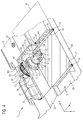
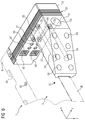
- FIGS. 1 to 7 show various representations and partial views of a lubricating device 1 for applying a lubricant during rolling of a rolling stock.
- FIG. 1 shows a perspective view of the entire lubricating device 1.
- the lubricating device 1 comprises an extruded profile 3, two terminal blocks 5, 6, a plurality of nozzles 7 and a nozzle protection frame. 9
- the extruded profile 3 is an elongated body which extends along its longitudinal axis between two profile ends 31, 32 of the extruded profile 3.
- the extruded profile 3 has a front-side section 33 with a front side 34 of the extruded profile 3 and a rear-side section 35 with a rear side 36 of the extruded profile 3 opposite the front side 34, wherein the front side 34 and the rear side 36 each extend in the longitudinal direction of the extruded profile 3, ie , H. extend parallel to its longitudinal axis.
- the front side 34 faces a surface to which the lubricant is applied.
- a first connection block 5 is arranged on a first profile end 31 of the extruded profile 3
- the second connection block 6 is arranged on the second profile end 32 of the extruded profile 3.
- the nozzles 7 are side by side along a straight line parallel to the longitudinal axis of the extruded profile 3 in the front-side section 33 of the extruded profile 3 used (see the FIGS. 3 to 5 ), in each case protruding from the extruded profile 3 on the front side 34 of the extruded profile 3.
- the nozzle protection frame 9 is arranged on the extruded profile 3, surrounds the front side 34 of the extruded profile 3 in a cap-like manner and extends parallel to the longitudinal axis of the extruded profile 3.
- the nozzle protection frame 9 is designed as a profile with a U-shaped cross section, the one for each nozzle 7 a Frame recess 91 has.
- the nozzle protection frame 9 protrudes further than the nozzles 7 from the front side 34 of the extruded profile 3 in order to protect the nozzles 7 from damage.
- FIGS. 1 to 7 a related to the extruded 3 Cartesian coordinate system with coordinates X, Y, Z, whose X-axis is parallel to the longitudinal axis of the extruded profile 3.
- the Y-axis of the coordinate system passes through the front 34 and through the back 36 of the extruded profile.
- the front 34 and the back 36 of the extruded profile 3 are each flat and perpendicular to the direction of the Y-axis. Furthermore, the profile ends 31, 32 in this embodiment to the longitudinal axis of the extruded profile 3 vertical surfaces of the extruded profile 3 and thus each parallel to a YZ plane of the coordinate system.
- FIGS. 2 to 4 show the extruded profile 3, the nozzles 7 and the nozzle protection frame 9 of the lubricating device 1 in detail.
- FIG. 2 shows a perspective view of the extruded profile 3, attached nozzles 7 and the nozzle guard frame 9, wherein the nozzle protection frame 9 is shown transparent.
- FIG. 3 shows a perspective sectional view of a portion of the lubricating device 1 with a plane parallel to the YZ plane cutting plane which passes through a nozzle 7.
- FIG. 4 shows a perspective view of a portion of the lubricating device 1, which is broken in the region of a nozzle 7 and shown in multiple cuts.
- lubricant channels 41 Extending through the extruded profile 3 parallel to the longitudinal axis a plurality of (eight in the illustrated embodiment) lubricant channels 41, two carrier medium channels 42 and a Düsenbefest onlysausnaturalung 43.
- the lubricant channels 41, the carrier medium channels 42 and the Düsenbefest onlysausNFung 43 each extend over the entire longitudinal extent of the extruded profile 3 and are respectively to both profile ends 31, 32 of the extruded profile 3 open.
- the lubricant channels 41 extend through the rear portion 35 of the extruded profile 3.
- the lubricant channels 41 form two rows of lubricant channels 41 (in the illustrated embodiment, two rows of four lubricant channels 41), the two rows are arranged on different sides of a median plane M of the extruded profile 3 and the lubricant channels 41 of each row are arranged side by side along a straight line parallel to the Y-axis.
- the median plane M runs parallel to an XY plane of the coordinate system through the extruded profile 3 and is at least approximately a plane of symmetry of the extruded profile 3.
- the carrier medium channels 42 and the Düsenbefest onlysausEnglishung 43 extend through the front-side portion 33 of the extruded profile 3.
- the support medium channels 42 extend at a greater distance from the front side 34 of the extruded profile 3 as the Düsenbefest onlysausEnglishung 43, d. H.
- the carrier medium channels 42 extend between the Düsenbefest onlysausANSung 43 and the lubricant channels 41 through the extruded profile 3.
- the carrier medium channels 42 extend on different sides of the center plane M. Die Düsenbefest onlysausANS 43 is symmetrical to the center plane M executed.
- the Düsenbefest onlysausNOung 43 is the front side, ie the front 34 of the extruded profile 3, limited by a front wall 37, the outer surface of which forms the front side 34 of the extruded profile 3.
- the nozzle attachment recess 43 is delimited by an intermediate wall 38 of the extruded profile 3, which separates the nozzle attachment recess 43 from the carrier medium channels 42.
- the carrier medium channels 42 are separated from each other by a partition wall 39, which from the intermediate wall 38 to the rear portion 35 of the extruded profile 3 extends.
- Each nozzle 7 is inserted into a nozzle recess 44, 45, 46 in the extruded profile 3.
- Each nozzle recess 44, 45, 46 consists of a front wall recess 44 in the front wall 37, a partition wall recess 45 in the intermediate wall 38 and a partition wall recess 46 in the partition wall 39.
- Each nozzle 7 is configured to produce and dispense a lubricant-carrier medium mixture of lubricant and a carrier medium.
- Each nozzle 7 has a nozzle body 71 and a nozzle head 72 connected to the nozzle body 71.
- the nozzle body 71 is a substantially cylindrical hollow body, which is closed on one side by a nozzle bottom 73 and open to the nozzle head 72.
- the nozzle bottom 73 has a carrier medium inlet 74 for introducing carrier medium into the nozzle 7.
- the nozzle body 71 has two lubricant inlets 75 for introducing lubricant into the nozzle 7, the lubricant inlets 75 being equidistant from the nozzle bottom 73.
- the nozzle head 72 is cap-mounted on the nozzle body 71 and has a nozzle outlet 76 for dispensing the lubricant-carrier medium mixture.
- Each nozzle 7 is detachably connected to the extruded profile 3 by a bayonet coupling 77 to 80.
- the bayonet catch 77 to 80 comprises a bayonet collar 77, a support collar 78, a clamping spring 79 and a clamping ring 80.
- the bayonet collar 77, the support collar 78, the clamping spring 79 and the clamping ring 80 each extend annularly around a nozzle axis of the nozzle 7, between the Nozzle bottom 73 and the nozzle head 72 extends.
- the bayonet collar 77 is part of the nozzle body 71 and disposed between the lubricant inlets 75 and the nozzle head 72.
- the bayonet collar 77 protrudes outward from the rest of the nozzle body 71, having two opposing collar segments 77.1, 77.2 which project further outward than the areas of the bayonet collar 77 lying between them.
- the front wall recess 44 has a corresponding bayonet collar 77 Contour, so that the bayonet collar 77 can be performed only in a precise position relative to the front wall recess 44 through the front wall recess 44.
- the support collar 78 is part of the nozzle head 72 and projects annularly outward from the remaining nozzle head 72.
- the clamping ring 80 is disposed between the bayonet collar 77 and the nozzle head 72 and extends annularly around the outer surface of the nozzle body 71, being displaceable along the nozzle axis with respect to the nozzle body 71.
- An outer diameter of the clamping ring 80 is greater than the diameter of the front wall recess 44, so that it can not be guided by the front wall recess 44.
- the clamping spring 79 is disposed between the support collar 78 of the nozzle head 72 and the clamping ring 80 and is supported with a front end on the support collar 78 and with a rear end on the clamping ring 80 from.
- the clamping spring 79 is elastically deformable and biased in the direction of the nozzle axis, so that it exerts a restoring force in the direction of the bayonet collar 77 on the clamping ring 80.
- the nozzle 7 In order to fasten a nozzle 7 to the extruded profile 3, the nozzle 7 is inserted from the front side 34 into a nozzle recess 44, 45, 46, wherein the bayonet collar 77 is guided through the front wall recess 44 with a precise fit. Subsequently, the nozzle 7 is rotated about 90 degrees about its nozzle axis and released. As a result, the collar segments 77.1, 77.2 bear against the rear surface of the front wall 37, and the clamping ring 80 bears against the front surface of the front wall 37. Further, the clamping spring 79 exerts a restoring force on the clamping ring 80, which presses the clamping ring 80 to the front wall 37 and the nozzle 7 thus secured in the extruded profile 3.
- the nozzle 7 is rotated according to its nozzle axis until its bayonet collar 77 can be passed through the front wall recess 44 and the nozzle 7 then from the nozzle recess 44, 45, 46 pulled.
- the bayonet closure 77 to 80 advantageously allows a detachable and tool-free installation, removal and replacement of nozzles. 7
- Each nozzle 7 is connected via a first branch channel 47 and a second branch channel 48 with a running through the extruded profile 3 lubricant channel 41.
- Each first puncture channel 47 extends straight from the back 36 of the extruded profile 3 parallel to the Y-axis between the two rows of lubricant channels 41 through the rear portion 35 of the extruded profile 3, through the partition wall 39 into the intermediate wall 38 and ends in the intermediate wall 38 Height of the lubricant inlets 75 of a fixed in the extruded profile 3 nozzle 7, to which the first embroidery channel 47 extends.
- Each second branch channel 48 extends from the outside parallel to the Z-axis through the rear portion 35 of the extruded profile 3 to a lubricant channel 41 and from this lubricant channel 41 to a first branch channel 47 and thereby connects the lubricant channel 41 with the first branch channel 47th
- Each Eisenwandausnaturalung 45 has an annular recess extension 49 which extends at the level of the lubricant inlets 75 of a nozzle 7, which is inserted into the nozzle recess 44, 45, 46 with this embandausnaturalung 45.
- the Ausnaturalungserweit réelle 49 of the insects supraung 45 forms after insertion of the nozzle 7 so an annular channel around the nozzle body 71 of this nozzle 7 at the level of lubricant inlets 75.
- the running to this nozzle 7 first branch channel 47 extends to the Ausappelungserweit réelle 49 and connects them by a second Branch channel 48 with a lubricant channel 41st
- the annular channel formed by a Ausnaturalungserweittation 49 to the nozzle body 71 of a nozzle 7 is sealed by two sealing rings 10, 11, which are introduced into the outer surface of the nozzle body 71 of the nozzle 7, extend around the nozzle axis of the nozzle 7 and abut the intermediate wall 38 ,
- a first sealing ring 10 at a smaller distance to the nozzle bottom 73 as the lubricant inlets 75 and seals the annular channel from the back.
- the second sealing ring 11 has a greater distance to the nozzle bottom 73 as the lubricant inlets 75 and seals the annular channel from the front.
- Each partition wall recess 46 is made so deep that it connects both carrier medium channels 42 with the carrier medium inlet 74 of a nozzle 7 inserted into the associated nozzle recess 44, 45, 46.
- Each branch channel 47, 48 is closed to the outside with a blind plug 12.
- FIG. 4 also shows one of a plurality of screw connections 92, with which the nozzle protection frame 9 is attached to the extruded profile 3.
- FIGS. 5 to 7 show the first terminal block 5 and its connection to the extruded profile.
- FIG. 5 shows a perspective sectional view of the first terminal block 5 having end portion of the lubricating device 1 with the center plane M as a cutting plane.
- FIG. 6 shows a perspective view of the first terminal block 5 and transparent end portions of the extruded profile 3 and the nozzle protection frame.
- FIG. 7 shows an exploded perspective view of the first terminal block 5 of the lubricating device 1.
- the second terminal block 6 is analogous to the first terminal block 5 executed. Therefore, only the first terminal block 5 will be described below.
- the first port block 5 includes a port segment 51, a lubricant bypass segment 52, and a carrier media bypass segment 53.
- connection segment 51 bears against the rear side 36 of the extruded profile 3 and terminates at the profile end flush with the first profiled end 31 of the extruded profile 3. As a result, the connection segment 51 is not laterally from the extruded profile 3, which causes a space-saving design of the lubricating device 1, which in particular allows rapid installation and removal of the lubricating device 1 in a rolling mill.
- the lubricant diverter segment 52 abuts against the first profile end 31 of the extruded profile 3 and on the connection segment 51.
- the carrier medium diverting segment 53 bears against a side of the lubricant diverter segment 52 facing away from the extruded profile 3.
- connection segment 51 a plurality of (in the illustrated embodiment, eight) lubricant connection channels 54 and a carrier medium connection channel 55 extend to the lubricant diversion segment 52
- FIG. 5 the course of the carrier medium connection channel 55 is shown in FIG FIG. 6
- FIG. 7 the course of all lubricant connection channels 54 and the carrier medium connection channel 55 is shown.
- Schmierumum In the Schmierumum Oberssegment 52 a plurality of (eight in the illustrated embodiment) lubricant lines 56, 57, 58, each connecting a lubricant connection channel 54 of the first connection block 5 with a lubricant passage 41 of the extruded profile 3 and deflect the lubricant from the lubricant connection channel 54 to the lubricant passage 41.
- connection line 56, 57, 58 consists of a lubricant connection channel extension 56 which extends a lubricant connection channel 54 of the connection segment 51 linearly into the lubricant bypass segment 52, a lubricant channel extension 57 which linearly extends a lubricant channel 41 of the extruded profile 3 into the lubricant diversion segment 52, and a lubricant connection channel 58, which connects a lubricant port passage extension 56 with a lubricant passage extension 57.
- the lubricant bypass segment 52 further extends a carrier media port extension 59 which extends the carrier media port 55 of the port segment 51 to the carrier media diverter segment 53 and two carrier media channel extensions 60 each extending one of the two carrier media channels 42 of the extruded profile 3 to the carrier media diverter segment 53.
- a carrier medium connection channel 61 connects the carrier medium port extension 59 to the two carrier medium channel extensions 60 and redirects the carrier medium.
- the lubricant diverter segment 52 comprises a stack of sheets of several stacked sheets 62, 63 and optionally a plate-shaped seal 64, which is arranged between the sheet stack and the extruded profile 3 and the connection segment 51.
- the plates 62, 63 and the seal 64 each have recesses 65 to 67, which form the lubricant lines 56, 57, 58, the carrier medium connection channel extension 59 and carrier medium channel extensions 60.
- the sheet stack is formed by connecting plates 62 and separating plates 63, which alternate with each other, so that in each case a connecting plate 62 is arranged between two separating plates 63.
- Each lubricant connection channel 58 is formed by exactly one elongated connection recess 65 in a connection plate 62.
- the lubricant port passage extension 56 connected to a lubricant communication passage 58 and the lubricant passage extension 57 connected to this lubricant passage port 58 are respectively arranged by successively stacked stack recesses 66 in all of the plates 62, 63 disposed between the seal 64 and the connection plate 62 forming the lubricant communication passage 58. and formed in the seal 64.
- Each connecting recess 65 in a connecting plate 62 is completely covered by the separating plate 63 arranged behind the connecting plate 62 and by the separating plate 63 arranged in front of the connecting plate 62 except for those areas covered, which are behind stack recesses 66 in this baffle 63.
- a sheet 62, 63 is referred to as behind another sheet 62, 63 disposed when it is closer to the Stromermediumum Oberssegment 53.
- each connecting plate 62 has two connecting recesses 65 and accordingly forms with the adjacent separating plates 63 two lubricant connection channels 58.
- the carrier media port extension 59 and the carrier media channel extensions 60 are each formed by successively disposed carrier media channel recesses 67 in each of the sheets 62, 63 and the seal 64.
- the separating plates 63 have a smaller thickness than the connecting plates 62.
- the terminal segment 51 has a lubricant connection opening 68 for each lubricant connection channel 54 and a carrier medium connection opening 69 for the carrier medium connection channel 55 to a rear outside of the connection segment 51.
- the carrier medium connection opening 69 is closer to the Schmierumum einssegment 52 than the lubricant connection openings 68.
- the rear side of the terminal segment 51 in the region of the lubricant connection openings 68 with respect to the back 36 of the extruded profile 3 is chamfered, with their distance from the back 36 of the extruded profile 3 with increasing distance from the lubricant diverter segment 52 is reduced.
- the extruded profile 3 is made for example of aluminum or copper or an aluminum alloy or a copper alloy.
- the seal 64 is made of, for example, nitrile rubber or fluororubber.
- the sheets 62, 63 are made of stainless steel or an aluminum alloy, for example.
- the extruded profile 3 is produced by first a semi-finished product with the lubricant channels 41, carrier medium channels 42 and the Düsenbefest onlysaus principleung 43 is produced in an extrusion process.
- the semi-finished product is then cut to a length that depends on an extent of a lubrication area to be lubricated.
- the puncture channels 47, 48 are closed by blind plugs 12.
- the recesses 65 to 67 in the sheets 62, 63 are cut out, for example by laser cutting.
- the sheets 62, 63 of a lubricant diversion segment 52 are adhesively bonded together in a liquid-tight manner to form a stack of sheets and then screwed on.
- each terminal block 5, 6 attached to a profile end 31, 32 of the extruded profile 3 (for example, in the FIGS. 1 to 7 Screws not shown)
- the nozzles 7 are each as described above in a nozzle recess 44, 45, 46 of the Extruded profile 3 is used, and the nozzle protection frame 9 is fastened by the screw 92 to the extruded profile 3.
- the lubricating device 1 During operation of the lubricating device 1, its front side 34 faces a surface onto which lubricant is to be dispensed, for example a surface of a roll of a rolling stand or of a rolling stock.
- a lubricant Through the lubricant connection openings 68 of the terminal blocks 5, 6, the lubricating device 1 is supplied with a lubricant, which is passed via the terminal blocks 5, 6 and the lubricant channels 41 and branch channels 47, 48 of the extruded profile 3 to the nozzles 7.
- the lubricating device 1 is supplied with a carrier medium through the carrier medium port openings 69 of the terminal blocks 5, 6, which is led to the nozzles 7 via the terminal blocks 5, 6 and the carrier medium channels 42.
- the lubricant is for example a rolling oil.
- the carrier medium is a gas, for. As air, or a liquid, for. B. water.
- Each nozzle 7 generates a lubricant-carrier medium mixture from the lubricant and carrier medium supplied to it and discharges this through its nozzle outlet 76 in the form of a spray jet.
Landscapes
- Engineering & Computer Science (AREA)
- Mechanical Engineering (AREA)
- Coating Apparatus (AREA)
- Rolling Contact Bearings (AREA)
- Extrusion Moulding Of Plastics Or The Like (AREA)
- Lubricants (AREA)
- Nozzles (AREA)
- Metal Rolling (AREA)
- General Details Of Gearings (AREA)
Priority Applications (9)
| Application Number | Priority Date | Filing Date | Title |
|---|---|---|---|
| EP16172663.3A EP3251762B1 (fr) | 2016-06-02 | 2016-06-02 | Dispositif de lubrification pour l'application d'un lubrifiant lors du laminage d'un produit de laminage |
| KR1020187034834A KR102347115B1 (ko) | 2016-06-02 | 2017-05-31 | 압연 재료의 압연시 윤활유를 도포하기 위한 윤활 장치 |
| MX2018014691A MX385990B (es) | 2016-06-02 | 2017-05-31 | Dispositivo de lubricación para aplicar un lubricante durante la laminación de un material laminado. |
| JP2018563153A JP6672486B2 (ja) | 2016-06-02 | 2017-05-31 | 圧延材料を圧延する際の潤滑剤を塗布するための潤滑装置 |
| US16/305,104 US11440067B2 (en) | 2016-06-02 | 2017-05-31 | Lubricating device for applying a lubricant when rolling a rolling material |
| PCT/EP2017/063139 WO2017207622A1 (fr) | 2016-06-02 | 2017-05-31 | Dispositif de lubrification destiné à appliquer un lubrifiant lors du laminage d'un produit à laminer |
| CN201780034057.5A CN109153053B (zh) | 2016-06-02 | 2017-05-31 | 用于在轧制轧件时施加润滑剂的润滑装置 |
| EP17726323.3A EP3463705A1 (fr) | 2016-06-02 | 2017-05-31 | Dispositif de lubrification destiné à appliquer un lubrifiant lors du laminage d'un produit à laminer |
| RU2018144627A RU2704877C1 (ru) | 2016-06-02 | 2017-05-31 | Смазочное устройство для нанесения смазочного средства при прокатке прокатываемого материала |
Applications Claiming Priority (1)
| Application Number | Priority Date | Filing Date | Title |
|---|---|---|---|
| EP16172663.3A EP3251762B1 (fr) | 2016-06-02 | 2016-06-02 | Dispositif de lubrification pour l'application d'un lubrifiant lors du laminage d'un produit de laminage |
Publications (2)
| Publication Number | Publication Date |
|---|---|
| EP3251762A1 true EP3251762A1 (fr) | 2017-12-06 |
| EP3251762B1 EP3251762B1 (fr) | 2019-08-07 |
Family
ID=56098107
Family Applications (2)
| Application Number | Title | Priority Date | Filing Date |
|---|---|---|---|
| EP16172663.3A Active EP3251762B1 (fr) | 2016-06-02 | 2016-06-02 | Dispositif de lubrification pour l'application d'un lubrifiant lors du laminage d'un produit de laminage |
| EP17726323.3A Withdrawn EP3463705A1 (fr) | 2016-06-02 | 2017-05-31 | Dispositif de lubrification destiné à appliquer un lubrifiant lors du laminage d'un produit à laminer |
Family Applications After (1)
| Application Number | Title | Priority Date | Filing Date |
|---|---|---|---|
| EP17726323.3A Withdrawn EP3463705A1 (fr) | 2016-06-02 | 2017-05-31 | Dispositif de lubrification destiné à appliquer un lubrifiant lors du laminage d'un produit à laminer |
Country Status (8)
| Country | Link |
|---|---|
| US (1) | US11440067B2 (fr) |
| EP (2) | EP3251762B1 (fr) |
| JP (1) | JP6672486B2 (fr) |
| KR (1) | KR102347115B1 (fr) |
| CN (1) | CN109153053B (fr) |
| MX (1) | MX385990B (fr) |
| RU (1) | RU2704877C1 (fr) |
| WO (1) | WO2017207622A1 (fr) |
Cited By (1)
| Publication number | Priority date | Publication date | Assignee | Title |
|---|---|---|---|---|
| WO2021097568A1 (fr) * | 2019-11-18 | 2021-05-27 | Blue Solutions Canada Inc. | Unité de distribution de lubrifiant de laminage destinée à lubrifier un cylindre de travail d'un laminoir pour laminer une feuille de métal alcalin ou d'un alliage de celui-ci en un film |
Families Citing this family (4)
| Publication number | Priority date | Publication date | Assignee | Title |
|---|---|---|---|---|
| WO2019241547A1 (fr) | 2018-06-13 | 2019-12-19 | Novelis Inc. | Systèmes et procédés d'élimination de matériaux visqueux dans le traitement d'article métallique |
| KR102224516B1 (ko) * | 2018-06-13 | 2021-03-08 | 노벨리스 인크. | 롤 가공처리에서 점성 재료를 격납하기 위한 시스템 및 방법 |
| DE102020213287A1 (de) | 2020-10-21 | 2022-04-21 | Sms Group Gmbh | Modulares Spritzbalkensystem zur selektiven Kühlung und/oder Schmierung von Walzen |
| AT528309B1 (de) * | 2025-03-17 | 2025-12-15 | Andritz Metals Germany Gmbh | Variables kuehlsystem fuer baender und walzen |
Citations (6)
| Publication number | Priority date | Publication date | Assignee | Title |
|---|---|---|---|---|
| EP0153532A2 (fr) | 1984-02-20 | 1985-09-04 | DAVY McKEE (POOLE) LIMITED | Dispositif pour appliquer un liquide à un laminoir |
| EP0205295A2 (fr) * | 1985-06-10 | 1986-12-17 | DAVY McKEE (POOLE) LIMITED | Lubrification de laminoirs |
| CH686072A5 (de) | 1992-06-19 | 1995-12-29 | Alusuisse Lonza Services Ag | Sprayanlage zum Kuhlen von Profilen. |
| EP1142653A2 (fr) | 2000-04-08 | 2001-10-10 | ACHENBACH BUSCHHÜTTEN GmbH | Dispositif pour refroidir et/ou lubrifier des cylindres de laminoirs pour feuillards à froid, notamment feuillards fins et feuilles minces |
| EP1142652A2 (fr) | 2000-04-08 | 2001-10-10 | ACHENBACH BUSCHHÜTTEN GmbH | Dispositif pour refroidir et/ou lubrifier des cylindres de laminoirs pour feuillards à froid, notamment feuillards fins et feuilles minces |
| EP2465619A1 (fr) | 2010-12-16 | 2012-06-20 | Siemens VAI Metals Technologies GmbH | Procédé et dispositif d'application d'un lubrifiant lors du laminage d'un produit de laminage métallique |
Family Cites Families (21)
| Publication number | Priority date | Publication date | Assignee | Title |
|---|---|---|---|---|
| JPS6110771Y2 (fr) * | 1979-10-08 | 1986-04-05 | ||
| JPS5659168A (en) | 1979-10-17 | 1981-05-22 | Matsushita Electric Industrial Co Ltd | Refrigerating cycle for air conditioner |
| SU929269A1 (ru) | 1980-10-24 | 1982-05-23 | Уральский научно-исследовательский институт черных металлов | Устройство дл нагнетани смазки к очагу деформации при прокатке |
| SU986533A1 (ru) | 1981-09-03 | 1983-01-07 | Уральский научно-исследовательский институт черных металлов | Устройство дл нагнетани смазки к зоне деформации |
| JPS58110119A (ja) * | 1981-12-22 | 1983-06-30 | Showa Alum Corp | 内外に複数の中空部を有する多孔押出型材の製造方法および同製造用ダイス |
| GB8514597D0 (en) * | 1985-06-10 | 1985-07-10 | Davy Mckee Poole | Lubrication of rolling mills |
| US4738400A (en) * | 1987-02-11 | 1988-04-19 | Almo Manifold & Tool Co. | Spray bar assembly |
| DE9207241U1 (de) * | 1992-06-01 | 1992-10-22 | Bachmann, Adolf, 3000 Hannover | Einrichtung zur Abluftreinigung |
| JP3287509B2 (ja) * | 1994-01-13 | 2002-06-04 | 川崎製鉄株式会社 | 熱間圧延機における潤滑圧延装置 |
| US5882573A (en) * | 1997-09-29 | 1999-03-16 | Illinois Tool Works Inc. | Adhesive dispensing nozzles for producing partial spray patterns and method therefor |
| JP2003181516A (ja) * | 2001-12-12 | 2003-07-02 | Jfe Steel Kk | 圧延潤滑剤の噴射方法およびその装置 |
| US7837131B2 (en) * | 2003-03-27 | 2010-11-23 | Spraying Systems Co. | Modular automatic spray gun manifold |
| JP4710491B2 (ja) * | 2004-08-31 | 2011-06-29 | ブラザー工業株式会社 | 液体移送装置 |
| JP5191683B2 (ja) | 2007-04-16 | 2013-05-08 | 新日鐵住金株式会社 | 冷却装置 |
| BE1017806A3 (fr) * | 2007-10-08 | 2009-07-07 | Ct Rech Metallurgiques Asbl | Installation et procede de lubrification par atomisation pour cylindres de laminage. |
| JP4924475B2 (ja) * | 2008-02-27 | 2012-04-25 | Jfeスチール株式会社 | ホットレベラおよび二重管 |
| US8881568B2 (en) | 2008-07-16 | 2014-11-11 | Jfe Steel Corporation | Cooling equipment and cooling method for hot rolled steel plate |
| IN2014DN05743A (fr) * | 2012-02-15 | 2015-04-10 | Siemens Vai Metals Tech Gmbh | |
| EP2893986A1 (fr) * | 2014-01-08 | 2015-07-15 | Siemens VAI Metals Technologies GmbH | Lubrification à l'aide de buses d'injection dotées de plusieurs orifices d'entrée d'huile |
| CN104907338B (zh) * | 2014-03-12 | 2017-01-04 | 中冶南方工程技术有限公司 | 热轧辊缝润滑装置及方法 |
| KR102372530B1 (ko) * | 2017-02-08 | 2022-03-08 | 오이엠 그룹, 엘엘씨 | 조절식 흐름 노즐 시스템 |
-
2016
- 2016-06-02 EP EP16172663.3A patent/EP3251762B1/fr active Active
-
2017
- 2017-05-31 EP EP17726323.3A patent/EP3463705A1/fr not_active Withdrawn
- 2017-05-31 MX MX2018014691A patent/MX385990B/es unknown
- 2017-05-31 JP JP2018563153A patent/JP6672486B2/ja active Active
- 2017-05-31 CN CN201780034057.5A patent/CN109153053B/zh active Active
- 2017-05-31 WO PCT/EP2017/063139 patent/WO2017207622A1/fr not_active Ceased
- 2017-05-31 RU RU2018144627A patent/RU2704877C1/ru active
- 2017-05-31 US US16/305,104 patent/US11440067B2/en active Active
- 2017-05-31 KR KR1020187034834A patent/KR102347115B1/ko active Active
Patent Citations (6)
| Publication number | Priority date | Publication date | Assignee | Title |
|---|---|---|---|---|
| EP0153532A2 (fr) | 1984-02-20 | 1985-09-04 | DAVY McKEE (POOLE) LIMITED | Dispositif pour appliquer un liquide à un laminoir |
| EP0205295A2 (fr) * | 1985-06-10 | 1986-12-17 | DAVY McKEE (POOLE) LIMITED | Lubrification de laminoirs |
| CH686072A5 (de) | 1992-06-19 | 1995-12-29 | Alusuisse Lonza Services Ag | Sprayanlage zum Kuhlen von Profilen. |
| EP1142653A2 (fr) | 2000-04-08 | 2001-10-10 | ACHENBACH BUSCHHÜTTEN GmbH | Dispositif pour refroidir et/ou lubrifier des cylindres de laminoirs pour feuillards à froid, notamment feuillards fins et feuilles minces |
| EP1142652A2 (fr) | 2000-04-08 | 2001-10-10 | ACHENBACH BUSCHHÜTTEN GmbH | Dispositif pour refroidir et/ou lubrifier des cylindres de laminoirs pour feuillards à froid, notamment feuillards fins et feuilles minces |
| EP2465619A1 (fr) | 2010-12-16 | 2012-06-20 | Siemens VAI Metals Technologies GmbH | Procédé et dispositif d'application d'un lubrifiant lors du laminage d'un produit de laminage métallique |
Cited By (2)
| Publication number | Priority date | Publication date | Assignee | Title |
|---|---|---|---|---|
| WO2021097568A1 (fr) * | 2019-11-18 | 2021-05-27 | Blue Solutions Canada Inc. | Unité de distribution de lubrifiant de laminage destinée à lubrifier un cylindre de travail d'un laminoir pour laminer une feuille de métal alcalin ou d'un alliage de celui-ci en un film |
| US11850643B2 (en) | 2019-11-18 | 2023-12-26 | Blue Solutions Canada Inc. | Lamination lubricant dispensing unit for lubricating a working roller of a rolling mill for laminating a sheet of alkali metal or alloy thereof into a film |
Also Published As
| Publication number | Publication date |
|---|---|
| US20200269295A1 (en) | 2020-08-27 |
| US11440067B2 (en) | 2022-09-13 |
| CN109153053A (zh) | 2019-01-04 |
| MX2018014691A (es) | 2019-02-28 |
| EP3251762B1 (fr) | 2019-08-07 |
| MX385990B (es) | 2025-03-18 |
| KR102347115B1 (ko) | 2022-01-03 |
| JP2019519375A (ja) | 2019-07-11 |
| RU2704877C1 (ru) | 2019-10-31 |
| WO2017207622A1 (fr) | 2017-12-07 |
| KR20190015271A (ko) | 2019-02-13 |
| JP6672486B2 (ja) | 2020-03-25 |
| EP3463705A1 (fr) | 2019-04-10 |
| CN109153053B (zh) | 2019-12-10 |
Similar Documents
| Publication | Publication Date | Title |
|---|---|---|
| EP3251762B1 (fr) | Dispositif de lubrification pour l'application d'un lubrifiant lors du laminage d'un produit de laminage | |
| DE69422599T2 (de) | Verfahren zum Bearbeiten von Werkstücken aus Titan oder Titanlegierungen sowie Sprühklemme dazu | |
| DE2612714A1 (de) | Einrichtung zur zerteilung gewalzter metallknueppel und bildung von mehrfach- stabmaterial | |
| DE102017214450B3 (de) | Spritzapparat und Verfahren zum Kühlen eines metallischen Strangs in einer Stranggießmaschine | |
| EP0737998A2 (fr) | Dispositif de dépÔt de couches minces sur un substrat | |
| DE29724492U1 (de) | Vorrichtung zum Aufteilen einer mittels einer Gasströmung transportierten viskosen Flüssigkeit | |
| EP1900449B1 (fr) | Poutre de pulvérisation d'une installation de décalaminage hydraulique et procédé de fonctionnement d'une telle poutre de pulvérisation | |
| EP2188073B1 (fr) | Cage de laminoir pour laminer des bandes métalliques et cylindres ou rouleaux pour ladite cage de laminoir | |
| EP0551834A1 (fr) | Dispositif à chambre fermée pour dispositif d'encrage court dans une rotative d'impression | |
| DE2003339B2 (de) | Vorrichtung zur speisung der blasoeffnungen im boden eines stahlkonverters | |
| EP0650776B1 (fr) | Dispositif pour réfroidir des bandes laminées | |
| EP4232215B1 (fr) | Système de rampe de pulvérisation modulaire pour refroidir et/ou lubrifier sélectivement des cylindres | |
| DE69605135T2 (de) | Untere Blockanordnung für ein metallisches Entgratergerät | |
| DE69300944T2 (de) | Verfahren und Vorrichtung zum Herstellen von einzelnen runden Stangen im warmen Zustand aus warmen Mehrfachelementen. | |
| DE20107440U1 (de) | Kalibrierhülse mit Intensivkühlung | |
| DE102011106494A1 (de) | Düsenvorrichtung und Strangführungsvorrichtung mit der Düsenvorrichtung | |
| DE102007011042A1 (de) | Verfahren zum Herstellen eines Sprühbalkens | |
| DE102016014269A1 (de) | Düsenvorrichtung mit zumindest zwei Düsenplatten und zumindest drei Öffnungen | |
| DE10295854B4 (de) | Vorrichtung zur Wärmebehandlung und hydraulischen Förderung von Walzgut | |
| EP2583760A1 (fr) | Tête de coucheuse à fontaine directe | |
| EP3281705A1 (fr) | Dispositif de à buses | |
| DE60303630T2 (de) | Vorrichtung sowie Verfahren zur Erzeugung von dünnem Bimetallband mit einer 2-Rollen-Giessvorrichtung | |
| DE3825839A1 (de) | Vorrichtung zum kuehlen und zum hydraulischen transport von unsymmetrischen walzprofilen | |
| DE10126882C2 (de) | Fluidstromformer | |
| DE2449934C3 (de) | Vorrichtung zur Schmiermittelzuführung in die Schmiermittelbohrungen der Achsen von Strangführungsrollen |
Legal Events
| Date | Code | Title | Description |
|---|---|---|---|
| PUAI | Public reference made under article 153(3) epc to a published international application that has entered the european phase |
Free format text: ORIGINAL CODE: 0009012 |
|
| STAA | Information on the status of an ep patent application or granted ep patent |
Free format text: STATUS: THE APPLICATION HAS BEEN PUBLISHED |
|
| AK | Designated contracting states |
Kind code of ref document: A1 Designated state(s): AL AT BE BG CH CY CZ DE DK EE ES FI FR GB GR HR HU IE IS IT LI LT LU LV MC MK MT NL NO PL PT RO RS SE SI SK SM TR |
|
| AX | Request for extension of the european patent |
Extension state: BA ME |
|
| STAA | Information on the status of an ep patent application or granted ep patent |
Free format text: STATUS: REQUEST FOR EXAMINATION WAS MADE |
|
| 17P | Request for examination filed |
Effective date: 20180606 |
|
| RBV | Designated contracting states (corrected) |
Designated state(s): AL AT BE BG CH CY CZ DE DK EE ES FI FR GB GR HR HU IE IS IT LI LT LU LV MC MK MT NL NO PL PT RO RS SE SI SK SM TR |
|
| RIC1 | Information provided on ipc code assigned before grant |
Ipc: B21B 45/02 20060101ALI20181127BHEP Ipc: B21B 27/10 20060101AFI20181127BHEP |
|
| GRAP | Despatch of communication of intention to grant a patent |
Free format text: ORIGINAL CODE: EPIDOSNIGR1 |
|
| STAA | Information on the status of an ep patent application or granted ep patent |
Free format text: STATUS: GRANT OF PATENT IS INTENDED |
|
| INTG | Intention to grant announced |
Effective date: 20190123 |
|
| GRAS | Grant fee paid |
Free format text: ORIGINAL CODE: EPIDOSNIGR3 |
|
| GRAA | (expected) grant |
Free format text: ORIGINAL CODE: 0009210 |
|
| STAA | Information on the status of an ep patent application or granted ep patent |
Free format text: STATUS: THE PATENT HAS BEEN GRANTED |
|
| AK | Designated contracting states |
Kind code of ref document: B1 Designated state(s): AL AT BE BG CH CY CZ DE DK EE ES FI FR GB GR HR HU IE IS IT LI LT LU LV MC MK MT NL NO PL PT RO RS SE SI SK SM TR |
|
| REG | Reference to a national code |
Ref country code: GB Ref legal event code: FG4D Free format text: NOT ENGLISH |
|
| REG | Reference to a national code |
Ref country code: CH Ref legal event code: EP Ref country code: AT Ref legal event code: REF Ref document number: 1163037 Country of ref document: AT Kind code of ref document: T Effective date: 20190815 |
|
| REG | Reference to a national code |
Ref country code: DE Ref legal event code: R096 Ref document number: 502016005870 Country of ref document: DE |
|
| REG | Reference to a national code |
Ref country code: IE Ref legal event code: FG4D Free format text: LANGUAGE OF EP DOCUMENT: GERMAN |
|
| REG | Reference to a national code |
Ref country code: NL Ref legal event code: MP Effective date: 20190807 |
|
| REG | Reference to a national code |
Ref country code: LT Ref legal event code: MG4D |
|
| PG25 | Lapsed in a contracting state [announced via postgrant information from national office to epo] |
Ref country code: HR Free format text: LAPSE BECAUSE OF FAILURE TO SUBMIT A TRANSLATION OF THE DESCRIPTION OR TO PAY THE FEE WITHIN THE PRESCRIBED TIME-LIMIT Effective date: 20190807 Ref country code: BG Free format text: LAPSE BECAUSE OF FAILURE TO SUBMIT A TRANSLATION OF THE DESCRIPTION OR TO PAY THE FEE WITHIN THE PRESCRIBED TIME-LIMIT Effective date: 20191107 Ref country code: NL Free format text: LAPSE BECAUSE OF FAILURE TO SUBMIT A TRANSLATION OF THE DESCRIPTION OR TO PAY THE FEE WITHIN THE PRESCRIBED TIME-LIMIT Effective date: 20190807 Ref country code: LT Free format text: LAPSE BECAUSE OF FAILURE TO SUBMIT A TRANSLATION OF THE DESCRIPTION OR TO PAY THE FEE WITHIN THE PRESCRIBED TIME-LIMIT Effective date: 20190807 Ref country code: FI Free format text: LAPSE BECAUSE OF FAILURE TO SUBMIT A TRANSLATION OF THE DESCRIPTION OR TO PAY THE FEE WITHIN THE PRESCRIBED TIME-LIMIT Effective date: 20190807 Ref country code: NO Free format text: LAPSE BECAUSE OF FAILURE TO SUBMIT A TRANSLATION OF THE DESCRIPTION OR TO PAY THE FEE WITHIN THE PRESCRIBED TIME-LIMIT Effective date: 20191107 Ref country code: SE Free format text: LAPSE BECAUSE OF FAILURE TO SUBMIT A TRANSLATION OF THE DESCRIPTION OR TO PAY THE FEE WITHIN THE PRESCRIBED TIME-LIMIT Effective date: 20190807 Ref country code: PT Free format text: LAPSE BECAUSE OF FAILURE TO SUBMIT A TRANSLATION OF THE DESCRIPTION OR TO PAY THE FEE WITHIN THE PRESCRIBED TIME-LIMIT Effective date: 20191209 |
|
| PG25 | Lapsed in a contracting state [announced via postgrant information from national office to epo] |
Ref country code: IS Free format text: LAPSE BECAUSE OF FAILURE TO SUBMIT A TRANSLATION OF THE DESCRIPTION OR TO PAY THE FEE WITHIN THE PRESCRIBED TIME-LIMIT Effective date: 20191207 Ref country code: LV Free format text: LAPSE BECAUSE OF FAILURE TO SUBMIT A TRANSLATION OF THE DESCRIPTION OR TO PAY THE FEE WITHIN THE PRESCRIBED TIME-LIMIT Effective date: 20190807 Ref country code: AL Free format text: LAPSE BECAUSE OF FAILURE TO SUBMIT A TRANSLATION OF THE DESCRIPTION OR TO PAY THE FEE WITHIN THE PRESCRIBED TIME-LIMIT Effective date: 20190807 Ref country code: RS Free format text: LAPSE BECAUSE OF FAILURE TO SUBMIT A TRANSLATION OF THE DESCRIPTION OR TO PAY THE FEE WITHIN THE PRESCRIBED TIME-LIMIT Effective date: 20190807 Ref country code: GR Free format text: LAPSE BECAUSE OF FAILURE TO SUBMIT A TRANSLATION OF THE DESCRIPTION OR TO PAY THE FEE WITHIN THE PRESCRIBED TIME-LIMIT Effective date: 20191108 Ref country code: ES Free format text: LAPSE BECAUSE OF FAILURE TO SUBMIT A TRANSLATION OF THE DESCRIPTION OR TO PAY THE FEE WITHIN THE PRESCRIBED TIME-LIMIT Effective date: 20190807 |
|
| PG25 | Lapsed in a contracting state [announced via postgrant information from national office to epo] |
Ref country code: DK Free format text: LAPSE BECAUSE OF FAILURE TO SUBMIT A TRANSLATION OF THE DESCRIPTION OR TO PAY THE FEE WITHIN THE PRESCRIBED TIME-LIMIT Effective date: 20190807 Ref country code: PL Free format text: LAPSE BECAUSE OF FAILURE TO SUBMIT A TRANSLATION OF THE DESCRIPTION OR TO PAY THE FEE WITHIN THE PRESCRIBED TIME-LIMIT Effective date: 20190807 Ref country code: EE Free format text: LAPSE BECAUSE OF FAILURE TO SUBMIT A TRANSLATION OF THE DESCRIPTION OR TO PAY THE FEE WITHIN THE PRESCRIBED TIME-LIMIT Effective date: 20190807 Ref country code: RO Free format text: LAPSE BECAUSE OF FAILURE TO SUBMIT A TRANSLATION OF THE DESCRIPTION OR TO PAY THE FEE WITHIN THE PRESCRIBED TIME-LIMIT Effective date: 20190807 |
|
| PG25 | Lapsed in a contracting state [announced via postgrant information from national office to epo] |
Ref country code: SM Free format text: LAPSE BECAUSE OF FAILURE TO SUBMIT A TRANSLATION OF THE DESCRIPTION OR TO PAY THE FEE WITHIN THE PRESCRIBED TIME-LIMIT Effective date: 20190807 Ref country code: IS Free format text: LAPSE BECAUSE OF FAILURE TO SUBMIT A TRANSLATION OF THE DESCRIPTION OR TO PAY THE FEE WITHIN THE PRESCRIBED TIME-LIMIT Effective date: 20200224 Ref country code: CZ Free format text: LAPSE BECAUSE OF FAILURE TO SUBMIT A TRANSLATION OF THE DESCRIPTION OR TO PAY THE FEE WITHIN THE PRESCRIBED TIME-LIMIT Effective date: 20190807 Ref country code: SK Free format text: LAPSE BECAUSE OF FAILURE TO SUBMIT A TRANSLATION OF THE DESCRIPTION OR TO PAY THE FEE WITHIN THE PRESCRIBED TIME-LIMIT Effective date: 20190807 |
|
| REG | Reference to a national code |
Ref country code: DE Ref legal event code: R097 Ref document number: 502016005870 Country of ref document: DE |
|
| PLBE | No opposition filed within time limit |
Free format text: ORIGINAL CODE: 0009261 |
|
| STAA | Information on the status of an ep patent application or granted ep patent |
Free format text: STATUS: NO OPPOSITION FILED WITHIN TIME LIMIT |
|
| PG2D | Information on lapse in contracting state deleted |
Ref country code: IS |
|
| 26N | No opposition filed |
Effective date: 20200603 |
|
| PG25 | Lapsed in a contracting state [announced via postgrant information from national office to epo] |
Ref country code: SI Free format text: LAPSE BECAUSE OF FAILURE TO SUBMIT A TRANSLATION OF THE DESCRIPTION OR TO PAY THE FEE WITHIN THE PRESCRIBED TIME-LIMIT Effective date: 20190807 |
|
| PG25 | Lapsed in a contracting state [announced via postgrant information from national office to epo] |
Ref country code: MC Free format text: LAPSE BECAUSE OF FAILURE TO SUBMIT A TRANSLATION OF THE DESCRIPTION OR TO PAY THE FEE WITHIN THE PRESCRIBED TIME-LIMIT Effective date: 20190807 |
|
| REG | Reference to a national code |
Ref country code: CH Ref legal event code: PL |
|
| GBPC | Gb: european patent ceased through non-payment of renewal fee |
Effective date: 20200602 |
|
| PG25 | Lapsed in a contracting state [announced via postgrant information from national office to epo] |
Ref country code: LU Free format text: LAPSE BECAUSE OF NON-PAYMENT OF DUE FEES Effective date: 20200602 |
|
| REG | Reference to a national code |
Ref country code: BE Ref legal event code: MM Effective date: 20200630 |
|
| PG25 | Lapsed in a contracting state [announced via postgrant information from national office to epo] |
Ref country code: GB Free format text: LAPSE BECAUSE OF NON-PAYMENT OF DUE FEES Effective date: 20200602 Ref country code: IE Free format text: LAPSE BECAUSE OF NON-PAYMENT OF DUE FEES Effective date: 20200602 Ref country code: CH Free format text: LAPSE BECAUSE OF NON-PAYMENT OF DUE FEES Effective date: 20200630 Ref country code: LI Free format text: LAPSE BECAUSE OF NON-PAYMENT OF DUE FEES Effective date: 20200630 |
|
| PG25 | Lapsed in a contracting state [announced via postgrant information from national office to epo] |
Ref country code: BE Free format text: LAPSE BECAUSE OF NON-PAYMENT OF DUE FEES Effective date: 20200630 |
|
| PG25 | Lapsed in a contracting state [announced via postgrant information from national office to epo] |
Ref country code: MT Free format text: LAPSE BECAUSE OF FAILURE TO SUBMIT A TRANSLATION OF THE DESCRIPTION OR TO PAY THE FEE WITHIN THE PRESCRIBED TIME-LIMIT Effective date: 20190807 Ref country code: CY Free format text: LAPSE BECAUSE OF FAILURE TO SUBMIT A TRANSLATION OF THE DESCRIPTION OR TO PAY THE FEE WITHIN THE PRESCRIBED TIME-LIMIT Effective date: 20190807 |
|
| PG25 | Lapsed in a contracting state [announced via postgrant information from national office to epo] |
Ref country code: MK Free format text: LAPSE BECAUSE OF FAILURE TO SUBMIT A TRANSLATION OF THE DESCRIPTION OR TO PAY THE FEE WITHIN THE PRESCRIBED TIME-LIMIT Effective date: 20190807 |
|
| P01 | Opt-out of the competence of the unified patent court (upc) registered |
Effective date: 20230614 |
|
| PGFP | Annual fee paid to national office [announced via postgrant information from national office to epo] |
Ref country code: DE Payment date: 20250618 Year of fee payment: 10 |
|
| PGFP | Annual fee paid to national office [announced via postgrant information from national office to epo] |
Ref country code: FR Payment date: 20250625 Year of fee payment: 10 |
|
| REG | Reference to a national code |
Ref country code: DE Ref legal event code: R082 Ref document number: 502016005870 Country of ref document: DE Representative=s name: LINDNER BLAUMEIER, PATENT- UND RECHTSANWAELTE,, DE |
|
| PGFP | Annual fee paid to national office [announced via postgrant information from national office to epo] |
Ref country code: AT Payment date: 20250620 Year of fee payment: 10 |
|
| PGFP | Annual fee paid to national office [announced via postgrant information from national office to epo] |
Ref country code: TR Payment date: 20250527 Year of fee payment: 10 |
|
| PGFP | Annual fee paid to national office [announced via postgrant information from national office to epo] |
Ref country code: IT Payment date: 20250624 Year of fee payment: 10 |