EP0207029A2 - Elektromagnetisch gekoppelte Streifenantennen mit an Speiseleitungen kapazitiv gekoppelten Speisestreifen - Google Patents
Elektromagnetisch gekoppelte Streifenantennen mit an Speiseleitungen kapazitiv gekoppelten Speisestreifen Download PDFInfo
- Publication number
- EP0207029A2 EP0207029A2 EP86850212A EP86850212A EP0207029A2 EP 0207029 A2 EP0207029 A2 EP 0207029A2 EP 86850212 A EP86850212 A EP 86850212A EP 86850212 A EP86850212 A EP 86850212A EP 0207029 A2 EP0207029 A2 EP 0207029A2
- Authority
- EP
- European Patent Office
- Prior art keywords
- patches
- feeding
- feedlines
- radiating
- microstrip antenna
- Prior art date
- Legal status (The legal status is an assumption and is not a legal conclusion. Google has not performed a legal analysis and makes no representation as to the accuracy of the status listed.)
- Granted
Links
Images

Classifications
-
- H—ELECTRICITY
- H01—ELECTRIC ELEMENTS
- H01P—WAVEGUIDES; RESONATORS, LINES, OR OTHER DEVICES OF THE WAVEGUIDE TYPE
- H01P3/00—Waveguides; Transmission lines of the waveguide type
- H01P3/02—Waveguides; Transmission lines of the waveguide type with two longitudinal conductors
- H01P3/08—Microstrips; Strip lines
-
- H—ELECTRICITY
- H01—ELECTRIC ELEMENTS
- H01Q—ANTENNAS, i.e. RADIO AERIALS
- H01Q21/00—Antenna arrays or systems
- H01Q21/06—Arrays of individually energised antenna units similarly polarised and spaced apart
- H01Q21/061—Two dimensional planar arrays
- H01Q21/065—Patch antenna array
-
- H—ELECTRICITY
- H01—ELECTRIC ELEMENTS
- H01Q—ANTENNAS, i.e. RADIO AERIALS
- H01Q9/00—Electrically-short antennas having dimensions not more than twice the operating wavelength and consisting of conductive active radiating elements
- H01Q9/04—Resonant antennas
- H01Q9/0407—Substantially flat resonant element parallel to ground plane, e.g. patch antenna
- H01Q9/0414—Substantially flat resonant element parallel to ground plane, e.g. patch antenna in a stacked or folded configuration
-
- H—ELECTRICITY
- H01—ELECTRIC ELEMENTS
- H01Q—ANTENNAS, i.e. RADIO AERIALS
- H01Q9/00—Electrically-short antennas having dimensions not more than twice the operating wavelength and consisting of conductive active radiating elements
- H01Q9/04—Resonant antennas
- H01Q9/0407—Substantially flat resonant element parallel to ground plane, e.g. patch antenna
- H01Q9/0428—Substantially flat resonant element parallel to ground plane, e.g. patch antenna radiating a circular polarised wave
-
- H—ELECTRICITY
- H01—ELECTRIC ELEMENTS
- H01Q—ANTENNAS, i.e. RADIO AERIALS
- H01Q9/00—Electrically-short antennas having dimensions not more than twice the operating wavelength and consisting of conductive active radiating elements
- H01Q9/04—Resonant antennas
- H01Q9/0407—Substantially flat resonant element parallel to ground plane, e.g. patch antenna
- H01Q9/045—Substantially flat resonant element parallel to ground plane, e.g. patch antenna with particular feeding means
- H01Q9/0457—Substantially flat resonant element parallel to ground plane, e.g. patch antenna with particular feeding means electromagnetically coupled to the feed line
Definitions
- the present invention relates to an electromagnetically coupled microstrip patch (EMCP) antenna element whose feeding patch is capacitively coupled to a feedline.
- the feeding patch is electromagnetically coupled to a radiating patch.
- a plurality of such antennas may be combined to make an antenna array.
- Microstrip antennas have been used for years as compact radiators. However, they have suffered from a number of deficiencies. For example, they are generally inefficient radiators of electromagnetic radiation; they operate over a narrow bandwidth; and they have required complicated connection techniques to achieve linear and circular polarization, so that fabrication has been difficult.
- U.S. Patent No. 3,803,623 discloses a means for making microstrip antennas more efficient radiators of electromagnetic radiation.
- U.S. Patent No. 3,987,455 discloses a multiple-element microstrip antenna array having a broad operational bandwidth.
- U.S. Patent No. 4,067,016 discloses a circularly polarized microstrip antenna.
- U.S. Patent Nos 4,125,837, 4,125,838, 4,125,839, and 4,316,194 show microstrip antennas in which two feedpoints are employed to achieve circular polarization.
- Each element of the array has a discontinuity, so that the element has an irregular shape. Consequently, circular polarization at a low axial ratio is achieved.
- Each element is individually directly coupled via a coaxial feedline.
- Still another object of the invention is to provide a microstrip antenna having linearly polarized elements, and having a high axial ratio.
- the present invention has a plurality of radiating and feeding patches, each having perturbation segments, the feeding patches being electromagnetically coupled to the radiating patches, the feedline being capacitively coupled to the feeding patch. - (To achieve linear polarization, the perturbation segments are not required.)
- the feed network also can comprise active circuit components implemented using MIC or MMIC techniques, such as amplifiers and phase shifters to control the power distribution, the sidelobe levels, and the beam direction of the antenna.
- active circuit components implemented using MIC or MMIC techniques, such as amplifiers and phase shifters to control the power distribution, the sidelobe levels, and the beam direction of the antenna.
- the design described in this application can be scaled to operate in any frequency band, such as . L-band, S-band, X-band, K u -band, or K a- band.
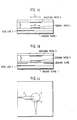
- a 50-ohm feedline 2 is truncated, tapered, or changed in shape in order to match the feedline to the mcirostrip antenna, and is capacitively coupled to a feeding patch 3, the feedline being disposed between the feeding patch and a ground plane 1.
- the feedline is implemented with microstrip, suspended substrate, stripline, finline, or coplanar waveguide technologies.
- the feedline and the feeding patch do not come into contact with each other. They are separated by a dielectric material, or by air.
- the feeding patch in turn is electromagnetically coupled to a radiating patch 4, the feeding patch and the radiating patch being separated by a distance S.
- a dielectric material or air may separate the feeding patch and the radiating patch.
- the feedline must be spaced an appropriate fraction of a wavelength of electromagnetic radiation from the feeding patch. Similarly, the distance S between the feeding patch and the radiating patch must be determined in accordance with the wavelength X.
- feeding patches and radiating patches in the Figures are circular, they may have any arbitrary but predefined shape.
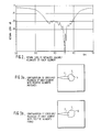
- Fig. 2 shows the return loss of an optimized linearly polarized, capacitively fed, electromagnetically coupled patch antenna of the type shown in Fig. 1 (a). It should be noted that a return loss of more then 20 dB is present on either side of a center frequency of 4.1 GHz.
- Fig. 3(a) shows the feedline capacitively coupled to a feeding patch having diametrically opposed notches 5 cut out, the notches being at a 45 degree angle relative to the capacitive feedline coupling.
- the feedline may be tapered, i.e. it becomes wider as it approaches the feeding patch to minimize resistance, sufficient space for only one feedpoint per feeding patch may be available. Consequently, in order to achieve circular polarization, the perturbation segments --either the notches shown in Fig. 3(a), or the tabs 6 shown in Fig. 3(b), the tabs being positioned in the same manner as the notches relative to the feedline --are necessary.
- Two diametrically opposed perturbation segments are provided for each patch. Other shapes and locations of perturbation segments are possible.
- Fig. 1 (c) Such a configuration is shown in Fig. 1 (c), in which feedlines 2 and 2' are placed orthogonal to each other with 90 degree phase shift in order to achieve circular polarization.
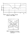
- Fig. 4 shows the return loss of an optimized circularly polarized, capacitively fed, electromagnetically coupled patch antenna of the type shown in Fig. 3(b). Note that a return loss of more than 20 dB is present on either side of a center frequency of 4.1 GHz.
- a plurality of elements making up an array are shown.
- the perturbation segments on each element are oriented differently with respect to the segment positionings on the other elements, though each feedline is positioned at the above-mentioned 45 degree orientation with respect to each diametrically-opposed pair of segments on each feeding patch.
- the line 7 feeds to a ring hybrid 8 which feeds two branch-line couplers 9 on a feed network board. This results in the feedlines 2 being at progressive 90 degree phase shifts from each other.
- Other feed networks producing the proper power division and phase progression can be used.
- the feeding patches are disposed such that they are in alignment with radiating patches (not numbered). That is, for any given pair comprising a feeding patch and a radiating patch, the tabs (or notches) are in register.
- the pairs are arranged such that the polarization of any two adjacent pairs is orthogonal. In other words, the perturbation segments of a feeding patch will be orthogonal with respect to the feeding patches adjacent thereto.
- Individual feedlines radiate to the feeding patches.
- the overall array may comprise three boards which do not contact each other: a feed network board; a feeding patch board; and a radiating patch board.
- Fig. 5 shows a four-element array
- any number of elements may be used to make an array, in order to obtain performance over a wider bandwidth.
- the perturbation segments must be positioned appropriately with respect to each other; for the four-element configuration, these segments are positioned orthogonally.
- a plurality of arrays having configuration similar to that shown in Fig. 5 may be combined to form an array as shown in Fig. 8.
- the Fig. 5 arrays may be thought of as subarrays.
- Each subarray may have a different number of elements.
- the perturbation segments on the elements in each subarray must be positioned appropriately within the subarray, as described above with respect to Fig. 5.
- the perturbation segments should be positioned at regular angular intervals within each subarray, such that the sum of the angular increments (phase shifts) between elements in each subarray is 360 degrees.
- the angular increment between the respective adjacent elements is 360/N, where N is the number of elements in a given subarray.
- Another parameter which may be varied is the size of the tabs or notches used as perturbation segments in relation to the length and width of the feeding and radiating patches.
- the size of the segments affects the extent and quality of circular polarization achieved.
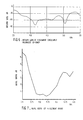
- Fig. 6 shows the return loss for a four-element microstrip antenna array fabricated according to the invention, and similar to the antenna array shown in Fig. 5. As can be seen, the overall return loss is close to 20 dB over 750 MHz, or about 18% bandwidth.
- Fig. 7 shows the axial ratio, which is the ratio of the major axis to the minor axis of polarization, for an optimal perturbation segment size.
- the axial ratio is less than 1 dB over 475 MHz, or about 12% bandwidth.
- the size of the perturbation segments may be varied to obtain different axial ratios.
- microstrip antenna arrays whose elements are linearly polarized or circularly polarized, which have high polarization purity, and which perform well over a wide bandwidth. All these features make a microstrip antenna manufactured according to the present invention attractive for use in MIC, MMIC, DBS, and other applications, as well as in other applications employing different frequency bands.
Landscapes
- Physics & Mathematics (AREA)
- Electromagnetism (AREA)
- Waveguide Aerials (AREA)
- Variable-Direction Aerials And Aerial Arrays (AREA)
Applications Claiming Priority (2)
| Application Number | Priority Date | Filing Date | Title |
|---|---|---|---|
| US06/748,637 US4761654A (en) | 1985-06-25 | 1985-06-25 | Electromagnetically coupled microstrip antennas having feeding patches capacitively coupled to feedlines |
| US748637 | 1985-06-25 |
Publications (3)
| Publication Number | Publication Date |
|---|---|
| EP0207029A2 true EP0207029A2 (de) | 1986-12-30 |
| EP0207029A3 EP0207029A3 (en) | 1989-01-11 |
| EP0207029B1 EP0207029B1 (de) | 1993-10-06 |
Family
ID=25010292
Family Applications (1)
| Application Number | Title | Priority Date | Filing Date |
|---|---|---|---|
| EP86850212A Expired - Lifetime EP0207029B1 (de) | 1985-06-25 | 1986-06-13 | Elektromagnetisch gekoppelte Streifenantennen mit an Speiseleitungen kapazitiv gekoppelten Speisestreifen |
Country Status (11)
| Country | Link |
|---|---|
| US (1) | US4761654A (de) |
| EP (1) | EP0207029B1 (de) |
| JP (1) | JPS621304A (de) |
| KR (1) | KR970011105B1 (de) |
| AU (1) | AU595271B2 (de) |
| BE (1) | BE906111A (de) |
| CA (1) | CA1263181A (de) |
| DE (1) | DE3689132T2 (de) |
| LU (1) | LU86727A1 (de) |
| NL (1) | NL8603317A (de) |
| SE (1) | SE458246B (de) |
Cited By (21)
| Publication number | Priority date | Publication date | Assignee | Title |
|---|---|---|---|---|
| EP0279050A1 (de) * | 1987-01-15 | 1988-08-24 | Ball Corporation | Antennenelement bestehend aus drei parasitär gekoppelten Streifenleitern |
| US4800392A (en) * | 1987-01-08 | 1989-01-24 | Motorola, Inc. | Integral laminar antenna and radio housing |
| FR2622056A1 (fr) * | 1987-10-15 | 1989-04-21 | Matsushita Electric Works Ltd | Antenne plane |
| FR2625616A1 (fr) * | 1987-12-15 | 1989-07-07 | Matsushita Electric Works Ltd | Antenne plane |
| US4847625A (en) * | 1988-02-16 | 1989-07-11 | Ford Aerospace Corporation | Wideband, aperture-coupled microstrip antenna |
| EP0348370A3 (en) * | 1988-06-23 | 1990-02-28 | Communications Satellite Corporation | Low noise block down-converter for direct broadcast satellite receiver integrated with a flat plate antenna |
| US4926189A (en) * | 1988-05-10 | 1990-05-15 | Communications Satellite Corporation | High-gain single- and dual-polarized antennas employing gridded printed-circuit elements |
| EP0271458A3 (en) * | 1986-11-13 | 1990-07-04 | Communications Satellite Corporation | Electromagnetically coupled printed-circuit antennas having patches or slots capacitively coupled to feedlines |
| FR2651926A1 (fr) * | 1989-09-11 | 1991-03-15 | Alcatel Espace | Antenne plane. |
| GB2220525B (en) * | 1988-07-08 | 1991-10-30 | Marconi Co Ltd | Waveguide coupling arrangement |
| EP0398555A3 (de) * | 1989-05-16 | 1991-11-06 | Hughes Aircraft Company | Leichte und flache phasengesteuerte Gruppenantenne mit elektromagnetisch gekoppelten integrierten Untergruppen |
| EP0468413A3 (en) * | 1990-07-25 | 1992-08-12 | Hitachi Chemical Co., Ltd. | Plane antenna with high gain and antenna efficiency |
| EP0516440A1 (de) * | 1991-05-30 | 1992-12-02 | Kabushiki Kaisha Toshiba | Mikrostreifenantenne |
| US5278569A (en) * | 1990-07-25 | 1994-01-11 | Hitachi Chemical Company, Ltd. | Plane antenna with high gain and antenna efficiency |
| FR2697374A1 (fr) * | 1992-10-28 | 1994-04-29 | Ball Corp | Ensemble à microbandes multicouches et son procédé de fabrication. |
| DE4442894A1 (de) * | 1994-12-02 | 1996-06-13 | Dettling & Oberhaeusser Ing | Empfangsmodul für den Empfang höchstfrequenter elektromagnetischer Richtstrahlungsfelder |
| WO1999000866A1 (en) * | 1997-06-27 | 1999-01-07 | Telefonaktiebolaget Lm Ericsson | Microstrip structure |
| US6239750B1 (en) | 1998-08-28 | 2001-05-29 | Telefonaltiebolaget Lm Ericsson (Publ) | Antenna arrangement |
| WO2006072511A1 (de) * | 2004-12-30 | 2006-07-13 | Robert Bosch Gmbh | Antennenanordnung für einen radar-transceiver |
| US7402335B2 (en) | 2003-07-09 | 2008-07-22 | Siemens Aktiengesellschaft | Layer structure and method for producing such a layer structure |
| CN111095675A (zh) * | 2017-10-03 | 2020-05-01 | 英特尔公司 | 混合且薄化的毫米波天线解决方案 |
Families Citing this family (76)
| Publication number | Priority date | Publication date | Assignee | Title |
|---|---|---|---|---|
| US4943809A (en) * | 1985-06-25 | 1990-07-24 | Communications Satellite Corporation | Electromagnetically coupled microstrip antennas having feeding patches capacitively coupled to feedlines |
| CA1263745A (en) * | 1985-12-03 | 1989-12-05 | Nippon Telegraph & Telephone Corporation | Shorted microstrip antenna |
| JPH0720008B2 (ja) * | 1986-02-25 | 1995-03-06 | 松下電工株式会社 | 平面アンテナ |
| JPS62216409A (ja) * | 1986-03-17 | 1987-09-24 | Aisin Seiki Co Ltd | アンテナ装置 |
| JPH0712122B2 (ja) * | 1986-08-14 | 1995-02-08 | 松下電工株式会社 | 平面アンテナ |
| JPS63258102A (ja) * | 1987-04-15 | 1988-10-25 | Matsushita Electric Works Ltd | 平面アンテナ |
| JPS63199503A (ja) * | 1987-02-13 | 1988-08-18 | Nippon Hoso Kyokai <Nhk> | マイクロストリツプアンテナ |
| US4972196A (en) * | 1987-09-15 | 1990-11-20 | Board Of Trustees Of The Univ. Of Illinois | Broadband, unidirectional patch antenna |
| FR2623020B1 (fr) * | 1987-11-05 | 1990-02-16 | Alcatel Espace | Dispositif d'excitation d'un guide d'onde en polarisation circulaire par une antenne plane |
| GB8803451D0 (en) * | 1988-02-15 | 1988-03-16 | British Telecomm | Antenna |
| US4903033A (en) * | 1988-04-01 | 1990-02-20 | Ford Aerospace Corporation | Planar dual polarization antenna |
| JPH07101811B2 (ja) * | 1988-05-13 | 1995-11-01 | 八木アンテナ株式会社 | ビームチルト平面アンテナ |
| US5181042A (en) * | 1988-05-13 | 1993-01-19 | Yagi Antenna Co., Ltd. | Microstrip array antenna |
| US5001492A (en) * | 1988-10-11 | 1991-03-19 | Hughes Aircraft Company | Plural layer co-planar waveguide coupling system for feeding a patch radiator array |
| JPH02162804A (ja) * | 1988-12-16 | 1990-06-22 | Nissan Motor Co Ltd | 平板型アンテナ |
| JPH0286206U (de) * | 1988-12-20 | 1990-07-09 | ||
| JPH02174304A (ja) * | 1988-12-26 | 1990-07-05 | Dx Antenna Co Ltd | 平面アンテナ |
| US5291210A (en) * | 1988-12-27 | 1994-03-01 | Harada Kogyo Kabushiki Kaisha | Flat-plate antenna with strip line resonator having capacitance for impedance matching the feeder |
| JPH02179008A (ja) * | 1988-12-28 | 1990-07-12 | Dx Antenna Co Ltd | 平面アンテナ |
| JPH02180408A (ja) * | 1988-12-29 | 1990-07-13 | Dx Antenna Co Ltd | 平面アンテナ |
| US5165109A (en) * | 1989-01-19 | 1992-11-17 | Trimble Navigation | Microwave communication antenna |
| US4980693A (en) * | 1989-03-02 | 1990-12-25 | Hughes Aircraft Company | Focal plane array antenna |
| US5270721A (en) * | 1989-05-15 | 1993-12-14 | Matsushita Electric Works, Ltd. | Planar antenna |
| US5075691A (en) * | 1989-07-24 | 1991-12-24 | Motorola, Inc. | Multi-resonant laminar antenna |
| US5187490A (en) * | 1989-08-25 | 1993-02-16 | Hitachi Chemical Company, Ltd. | Stripline patch antenna with slot plate |
| JP2536194B2 (ja) * | 1989-10-31 | 1996-09-18 | 三菱電機株式会社 | マイクロストリップアンテナ |
| JPH03148902A (ja) * | 1989-11-02 | 1991-06-25 | Dx Antenna Co Ltd | 平面アンテナ |
| US5321411A (en) * | 1990-01-26 | 1994-06-14 | Matsushita Electric Works, Ltd. | Planar antenna for linearly polarized waves |
| JPH04183003A (ja) * | 1990-11-16 | 1992-06-30 | A T R Koudenpa Tsushin Kenkyusho:Kk | トリプレート型アンテナ |
| CA2059364A1 (en) * | 1991-01-30 | 1992-07-31 | Eric C. Kohls | Waveguide transition for flat plate antenna |
| FR2672437B1 (fr) * | 1991-02-01 | 1993-09-17 | Alcatel Espace | Dispositif rayonnant pour antenne plane. |
| CA2061254C (en) * | 1991-03-06 | 2001-07-03 | Jean Francois Zurcher | Planar antennas |
| US5231406A (en) * | 1991-04-05 | 1993-07-27 | Ball Corporation | Broadband circular polarization satellite antenna |
| JP2604947B2 (ja) * | 1991-09-16 | 1997-04-30 | エルジー電子株式会社 | 平面アンテナ |
| GB9220414D0 (en) * | 1992-09-28 | 1992-11-11 | Pilkington Plc | Patch antenna assembly |
| US5471221A (en) * | 1994-06-27 | 1995-11-28 | The United States Of America As Represented By The Secretary Of The Army | Dual-frequency microstrip antenna with inserted strips |
| US5467094A (en) | 1994-06-28 | 1995-11-14 | Comsat Corporation | Flat antenna low-noise block down converter capacitively coupled to feed network |
| GB9417401D0 (en) * | 1994-08-30 | 1994-10-19 | Pilkington Plc | Patch antenna assembly |
| US5661494A (en) * | 1995-03-24 | 1997-08-26 | The United States Of America As Represented By The Administrator Of The National Aeronautics And Space Administration | High performance circularly polarized microstrip antenna |
| US5572172A (en) * | 1995-08-09 | 1996-11-05 | Qualcomm Incorporated | 180° power divider for a helix antenna |
| SE511497C2 (sv) * | 1997-02-25 | 1999-10-11 | Ericsson Telefon Ab L M | Anordning för att mottaga och sända radiosignaler |
| KR100207600B1 (ko) * | 1997-03-31 | 1999-07-15 | 윤종용 | 공진기 부착형 마이크로스트립 다이폴 안테나 어레이 |
| US6011522A (en) * | 1998-03-17 | 2000-01-04 | Northrop Grumman Corporation | Conformal log-periodic antenna assembly |
| US6018323A (en) * | 1998-04-08 | 2000-01-25 | Northrop Grumman Corporation | Bidirectional broadband log-periodic antenna assembly |
| US6140965A (en) * | 1998-05-06 | 2000-10-31 | Northrop Grumman Corporation | Broad band patch antenna |
| US6181279B1 (en) | 1998-05-08 | 2001-01-30 | Northrop Grumman Corporation | Patch antenna with an electrically small ground plate using peripheral parasitic stubs |
| US6556169B1 (en) * | 1999-10-22 | 2003-04-29 | Kyocera Corporation | High frequency circuit integrated-type antenna component |
| US6288677B1 (en) | 1999-11-23 | 2001-09-11 | The United States Of America As Represented By The Administrator Of The National Aeronautics And Space Administration | Microstrip patch antenna and method |
| SE515764C2 (sv) * | 2000-02-22 | 2001-10-08 | Acreo Ab | Patch-antenn |
| US6407705B1 (en) * | 2000-06-27 | 2002-06-18 | Mohamed Said Sanad | Compact broadband high efficiency microstrip antenna for wireless modems |
| GB2383471A (en) * | 2001-12-19 | 2003-06-25 | Harada Ind | High-bandwidth multi-band antenna |
| US6866573B2 (en) | 2002-04-08 | 2005-03-15 | Conagra Foods, Inc. | Automated support member positioning and removing systems and related devices and methods |
| US6707348B2 (en) | 2002-04-23 | 2004-03-16 | Xytrans, Inc. | Microstrip-to-waveguide power combiner for radio frequency power combining |
| EP1564843A1 (de) * | 2004-02-11 | 2005-08-17 | Sony International (Europe) GmbH | Zirkular polarisierte Gruppenantenne |
| EP1622221A1 (de) * | 2004-02-11 | 2006-02-01 | Sony Deutschland GmbH | Zirkular polarisierte Gruppenantenne |
| TWI239681B (en) * | 2004-12-22 | 2005-09-11 | Tatung Co Ltd | Circularly polarized array antenna |
| US7126549B2 (en) * | 2004-12-29 | 2006-10-24 | Agc Automotive Americas R&D, Inc. | Slot coupling patch antenna |
| TW200830632A (en) * | 2007-01-05 | 2008-07-16 | Advanced Connection Tech Inc | Circular polarized antenna |
| US8164167B2 (en) * | 2007-03-09 | 2012-04-24 | Nanyang Technological University | Integrated circuit structure and a method of forming the same |
| KR101007157B1 (ko) * | 2007-10-05 | 2011-01-12 | 주식회사 에이스테크놀로지 | 방사 패턴의 방향을 제어하는 안테나 |
| TWI370580B (en) | 2007-12-27 | 2012-08-11 | Wistron Neweb Corp | Patch antenna and method of making same |
| TW200933974A (en) * | 2008-01-22 | 2009-08-01 | Asustek Comp Inc | Antenna modules and antenna structures thereof |
| DE102009005045A1 (de) * | 2009-01-13 | 2010-07-15 | Wilhelm Sihn Jr. Gmbh & Co. Kg | Patchantenne |
| JP5598257B2 (ja) * | 2010-10-28 | 2014-10-01 | カシオ計算機株式会社 | 電子機器 |
| US9425516B2 (en) * | 2012-07-06 | 2016-08-23 | The Ohio State University | Compact dual band GNSS antenna design |
| US9484635B2 (en) | 2014-07-07 | 2016-11-01 | Kim Poulson | Waveguide antenna assembly and system for electronic devices |
| WO2016048152A1 (en) * | 2014-09-24 | 2016-03-31 | The Antenna Company International N.V. | Blade antenna and wireless local area network comprising a blade antenna |
| US10361476B2 (en) * | 2015-05-26 | 2019-07-23 | Qualcomm Incorporated | Antenna structures for wireless communications |
| WO2020242783A2 (en) * | 2019-05-24 | 2020-12-03 | Commscope Technologies Llc | Wireless communication systems having patch-type antenna arrays therein that support large scan angle radiation |
| CN110311211B (zh) * | 2019-06-20 | 2025-05-06 | 成都天锐星通科技股份有限公司 | 一种微带接收天线、发射天线及车载相控阵天线 |
| CN111048891A (zh) * | 2019-12-02 | 2020-04-21 | 中国舰船研究设计中心 | 小型化组合式微带-对称阵子双频天线 |
| JP7420217B2 (ja) | 2020-03-16 | 2024-01-23 | 株式会社村田製作所 | アンテナモジュール |
| WO2021204362A1 (en) * | 2020-04-07 | 2021-10-14 | Huawei Technologies Co., Ltd. | Microstrip antenna device with center-fed antenna arrays |
| CN111751795B (zh) * | 2020-06-12 | 2024-09-24 | 中国船舶集团有限公司第七二四研究所 | 一种介质鳍线微带天线监测装置 |
| US12062863B2 (en) * | 2021-03-26 | 2024-08-13 | Sony Group Corporation | Antenna device |
| WO2024064159A1 (en) * | 2022-09-19 | 2024-03-28 | Viasat, Inc. | Multi-layer antenna element circular polarization antenna |
Family Cites Families (10)
| Publication number | Priority date | Publication date | Assignee | Title |
|---|---|---|---|---|
| US4054874A (en) * | 1975-06-11 | 1977-10-18 | Hughes Aircraft Company | Microstrip-dipole antenna elements and arrays thereof |
| GB2046530B (en) * | 1979-03-12 | 1983-04-20 | Secr Defence | Microstrip antenna structure |
| JPS56134804A (en) * | 1980-03-25 | 1981-10-21 | Mitsubishi Electric Corp | Tracking antenna |
| US4477813A (en) * | 1982-08-11 | 1984-10-16 | Ball Corporation | Microstrip antenna system having nonconductively coupled feedline |
| JPS59181706A (ja) * | 1983-03-30 | 1984-10-16 | Radio Res Lab | マイクロストリツプアンテナ |
| FR2550892B1 (fr) * | 1983-08-19 | 1986-01-24 | Labo Electronique Physique | Sortie d'antenne en guide d'onde pour une antenne plane hyperfrequence a reseau d'elements rayonnants ou recepteurs et systeme d'emission ou de reception de signaux hyperfrequences comprenant une antenne plane equipee d'une telle sortie d'antenne |
| US4554549A (en) * | 1983-09-19 | 1985-11-19 | Raytheon Company | Microstrip antenna with circular ring |
| US4623893A (en) * | 1983-12-06 | 1986-11-18 | State Of Israel, Ministry Of Defense, Rafael Armament & Development Authority | Microstrip antenna and antenna array |
| GB2152757B (en) * | 1984-01-05 | 1987-10-14 | Plessey Co Plc | Antenna |
| US4660047A (en) * | 1984-10-12 | 1987-04-21 | Itt Corporation | Microstrip antenna with resonator feed |
-
1985
- 1985-06-25 US US06/748,637 patent/US4761654A/en not_active Expired - Lifetime
-
1986
- 1986-06-13 EP EP86850212A patent/EP0207029B1/de not_active Expired - Lifetime
- 1986-06-13 DE DE86850212T patent/DE3689132T2/de not_active Expired - Lifetime
- 1986-06-21 JP JP61144025A patent/JPS621304A/ja active Pending
- 1986-12-18 CA CA000525797A patent/CA1263181A/en not_active Expired
- 1986-12-19 SE SE8605492A patent/SE458246B/sv not_active IP Right Cessation
- 1986-12-22 AU AU66829/86A patent/AU595271B2/en not_active Expired
- 1986-12-23 KR KR1019860011108A patent/KR970011105B1/ko not_active Expired - Lifetime
- 1986-12-29 NL NL8603317A patent/NL8603317A/nl not_active Application Discontinuation
- 1986-12-30 LU LU86727A patent/LU86727A1/fr unknown
- 1986-12-30 BE BE0/217654A patent/BE906111A/fr not_active IP Right Cessation
Cited By (29)
| Publication number | Priority date | Publication date | Assignee | Title |
|---|---|---|---|---|
| EP0271458A3 (en) * | 1986-11-13 | 1990-07-04 | Communications Satellite Corporation | Electromagnetically coupled printed-circuit antennas having patches or slots capacitively coupled to feedlines |
| US4800392A (en) * | 1987-01-08 | 1989-01-24 | Motorola, Inc. | Integral laminar antenna and radio housing |
| US4835538A (en) * | 1987-01-15 | 1989-05-30 | Ball Corporation | Three resonator parasitically coupled microstrip antenna array element |
| EP0279050A1 (de) * | 1987-01-15 | 1988-08-24 | Ball Corporation | Antennenelement bestehend aus drei parasitär gekoppelten Streifenleitern |
| NL8802499A (nl) * | 1987-10-15 | 1989-05-01 | Matsushita Electric Works Ltd | Planaire antenne. |
| FR2622056A1 (fr) * | 1987-10-15 | 1989-04-21 | Matsushita Electric Works Ltd | Antenne plane |
| FR2625616A1 (fr) * | 1987-12-15 | 1989-07-07 | Matsushita Electric Works Ltd | Antenne plane |
| US4847625A (en) * | 1988-02-16 | 1989-07-11 | Ford Aerospace Corporation | Wideband, aperture-coupled microstrip antenna |
| US4926189A (en) * | 1988-05-10 | 1990-05-15 | Communications Satellite Corporation | High-gain single- and dual-polarized antennas employing gridded printed-circuit elements |
| EP0348370A3 (en) * | 1988-06-23 | 1990-02-28 | Communications Satellite Corporation | Low noise block down-converter for direct broadcast satellite receiver integrated with a flat plate antenna |
| GB2220525B (en) * | 1988-07-08 | 1991-10-30 | Marconi Co Ltd | Waveguide coupling arrangement |
| EP0398555A3 (de) * | 1989-05-16 | 1991-11-06 | Hughes Aircraft Company | Leichte und flache phasengesteuerte Gruppenantenne mit elektromagnetisch gekoppelten integrierten Untergruppen |
| US5539420A (en) * | 1989-09-11 | 1996-07-23 | Alcatel Espace | Multilayered, planar antenna with annular feed slot, passive resonator and spurious wave traps |
| FR2651926A1 (fr) * | 1989-09-11 | 1991-03-15 | Alcatel Espace | Antenne plane. |
| EP0426972A1 (de) * | 1989-09-11 | 1991-05-15 | Alcatel Espace | Ebene Antenne |
| EP0468413A3 (en) * | 1990-07-25 | 1992-08-12 | Hitachi Chemical Co., Ltd. | Plane antenna with high gain and antenna efficiency |
| US5278569A (en) * | 1990-07-25 | 1994-01-11 | Hitachi Chemical Company, Ltd. | Plane antenna with high gain and antenna efficiency |
| US5287116A (en) * | 1991-05-30 | 1994-02-15 | Kabushiki Kaisha Toshiba | Array antenna generating circularly polarized waves with a plurality of microstrip antennas |
| EP0516440A1 (de) * | 1991-05-30 | 1992-12-02 | Kabushiki Kaisha Toshiba | Mikrostreifenantenne |
| FR2697374A1 (fr) * | 1992-10-28 | 1994-04-29 | Ball Corp | Ensemble à microbandes multicouches et son procédé de fabrication. |
| DE4442894A1 (de) * | 1994-12-02 | 1996-06-13 | Dettling & Oberhaeusser Ing | Empfangsmodul für den Empfang höchstfrequenter elektromagnetischer Richtstrahlungsfelder |
| US5977915A (en) * | 1997-06-27 | 1999-11-02 | Telefonaktiebolaget Lm Ericsson | Microstrip structure |
| WO1999000866A1 (en) * | 1997-06-27 | 1999-01-07 | Telefonaktiebolaget Lm Ericsson | Microstrip structure |
| US6239750B1 (en) | 1998-08-28 | 2001-05-29 | Telefonaltiebolaget Lm Ericsson (Publ) | Antenna arrangement |
| US7402335B2 (en) | 2003-07-09 | 2008-07-22 | Siemens Aktiengesellschaft | Layer structure and method for producing such a layer structure |
| WO2006072511A1 (de) * | 2004-12-30 | 2006-07-13 | Robert Bosch Gmbh | Antennenanordnung für einen radar-transceiver |
| US7671806B2 (en) | 2004-12-30 | 2010-03-02 | Robert Bosch Gmbh | Antenna system for a radar transceiver |
| CN111095675A (zh) * | 2017-10-03 | 2020-05-01 | 英特尔公司 | 混合且薄化的毫米波天线解决方案 |
| EP3692600A4 (de) * | 2017-10-03 | 2021-11-17 | INTEL Corporation | Hybride und verdünnte millimeterwellen-antennenlösungen |
Also Published As
| Publication number | Publication date |
|---|---|
| SE458246B (sv) | 1989-03-06 |
| DE3689132T2 (de) | 1994-05-11 |
| JPS621304A (ja) | 1987-01-07 |
| AU595271B2 (en) | 1990-03-29 |
| SE8605492L (sv) | 1988-06-20 |
| BE906111A (fr) | 1987-04-16 |
| KR880008471A (ko) | 1988-08-31 |
| KR970011105B1 (ko) | 1997-07-07 |
| DE3689132D1 (de) | 1993-11-11 |
| EP0207029B1 (de) | 1993-10-06 |
| CA1263181A (en) | 1989-11-21 |
| AU6682986A (en) | 1988-06-23 |
| LU86727A1 (fr) | 1987-05-04 |
| NL8603317A (nl) | 1988-07-18 |
| EP0207029A3 (en) | 1989-01-11 |
| US4761654A (en) | 1988-08-02 |
| SE8605492D0 (sv) | 1986-12-19 |
Similar Documents
| Publication | Publication Date | Title |
|---|---|---|
| US4761654A (en) | Electromagnetically coupled microstrip antennas having feeding patches capacitively coupled to feedlines | |
| US4943809A (en) | Electromagnetically coupled microstrip antennas having feeding patches capacitively coupled to feedlines | |
| US5005019A (en) | Electromagnetically coupled printed-circuit antennas having patches or slots capacitively coupled to feedlines | |
| US4125838A (en) | Dual asymmetrically fed electric microstrip dipole antennas | |
| US4973972A (en) | Stripline feed for a microstrip array of patch elements with teardrop shaped probes | |
| US6795021B2 (en) | Tunable multi-band antenna array | |
| US5410323A (en) | Planar antenna | |
| US4173019A (en) | Microstrip antenna array | |
| US8063832B1 (en) | Dual-feed series microstrip patch array | |
| US7705782B2 (en) | Microstrip array antenna | |
| EP1466386B1 (de) | Doppelschichtstromblattantenne mit erweiterter bandbreite | |
| US5187490A (en) | Stripline patch antenna with slot plate | |
| EP0355898A1 (de) | Ebene Antennengruppe mit gedruckten coplanaren Wellenleiter-Speiseleitungen in Zusammenwirkung mit Oeffnungen in einer Grundplatte | |
| US6483464B2 (en) | Patch dipole array antenna including a feed line organizer body and related methods | |
| WO1991012637A1 (en) | Antenna | |
| WO2002037608A2 (en) | Patch dipole array antenna and associated method of making | |
| US4918457A (en) | Antenna formed of strip transmission lines with non-conductive coupling | |
| EP0434268B1 (de) | Mikrostreifenleiterantenne | |
| Xu et al. | Research of dual-band dual circularly polarized wide-angle scanning phased array | |
| US7408519B2 (en) | Dual polarization antenna array with inter-element capacitive coupling plate and associated methods | |
| JP3344802B2 (ja) | 平面アンテナ | |
| CN121440141A (zh) | 一种基于siw馈电的宽带毫米波圆极化天线阵列 | |
| Huang | Stripline feed for a microstrip array of patch elements with teardrop shaped probes | |
| Sastry | Planar Slot-Array Antenna | |
| AU2002312556A1 (en) | Patchdipole array antenna including a feed line organizer body and related methods |
Legal Events
| Date | Code | Title | Description |
|---|---|---|---|
| PUAI | Public reference made under article 153(3) epc to a published international application that has entered the european phase |
Free format text: ORIGINAL CODE: 0009012 |
|
| AK | Designated contracting states |
Kind code of ref document: A2 Designated state(s): DE FR GB IT |
|
| PUAL | Search report despatched |
Free format text: ORIGINAL CODE: 0009013 |
|
| AK | Designated contracting states |
Kind code of ref document: A3 Designated state(s): DE FR GB IT |
|
| 17P | Request for examination filed |
Effective date: 19890408 |
|
| 17Q | First examination report despatched |
Effective date: 19890621 |
|
| ITF | It: translation for a ep patent filed | ||
| GRAA | (expected) grant |
Free format text: ORIGINAL CODE: 0009210 |
|
| AK | Designated contracting states |
Kind code of ref document: B1 Designated state(s): DE FR GB IT |
|
| REF | Corresponds to: |
Ref document number: 3689132 Country of ref document: DE Date of ref document: 19931111 |
|
| ITF | It: translation for a ep patent filed | ||
| ET | Fr: translation filed | ||
| PLBE | No opposition filed within time limit |
Free format text: ORIGINAL CODE: 0009261 |
|
| STAA | Information on the status of an ep patent application or granted ep patent |
Free format text: STATUS: NO OPPOSITION FILED WITHIN TIME LIMIT |
|
| 26N | No opposition filed | ||
| REG | Reference to a national code |
Ref country code: GB Ref legal event code: IF02 |
|
| PGFP | Annual fee paid to national office [announced via postgrant information from national office to epo] |
Ref country code: GB Payment date: 20050608 Year of fee payment: 20 |
|
| PGFP | Annual fee paid to national office [announced via postgrant information from national office to epo] |
Ref country code: FR Payment date: 20050617 Year of fee payment: 20 |
|
| PGFP | Annual fee paid to national office [announced via postgrant information from national office to epo] |
Ref country code: IT Payment date: 20050629 Year of fee payment: 20 |
|
| PGFP | Annual fee paid to national office [announced via postgrant information from national office to epo] |
Ref country code: DE Payment date: 20050801 Year of fee payment: 20 |
|
| PG25 | Lapsed in a contracting state [announced via postgrant information from national office to epo] |
Ref country code: GB Free format text: LAPSE BECAUSE OF EXPIRATION OF PROTECTION Effective date: 20060612 |
|
| REG | Reference to a national code |
Ref country code: GB Ref legal event code: PE20 |