EP0207448B1 - Procédé pour la récupération d'oxyde d'éthylène - Google Patents
Procédé pour la récupération d'oxyde d'éthylène Download PDFInfo
- Publication number
- EP0207448B1 EP0207448B1 EP86108722A EP86108722A EP0207448B1 EP 0207448 B1 EP0207448 B1 EP 0207448B1 EP 86108722 A EP86108722 A EP 86108722A EP 86108722 A EP86108722 A EP 86108722A EP 0207448 B1 EP0207448 B1 EP 0207448B1
- Authority
- EP
- European Patent Office
- Prior art keywords
- ethylene oxide
- stripper
- liquid
- conduit
- refiner
- Prior art date
- Legal status (The legal status is an assumption and is not a legal conclusion. Google has not performed a legal analysis and makes no representation as to the accuracy of the status listed.)
- Expired - Lifetime
Links
- IAYPIBMASNFSPL-UHFFFAOYSA-N Ethylene oxide Chemical compound C1CO1 IAYPIBMASNFSPL-UHFFFAOYSA-N 0.000 title claims description 362
- 238000000034 method Methods 0.000 title claims description 60
- 238000011084 recovery Methods 0.000 title claims description 18
- 239000007788 liquid Substances 0.000 claims description 198
- 239000006096 absorbing agent Substances 0.000 claims description 74
- 239000007789 gas Substances 0.000 claims description 64
- 239000002250 absorbent Substances 0.000 claims description 58
- 230000002745 absorbent Effects 0.000 claims description 58
- XLYOFNOQVPJJNP-UHFFFAOYSA-N water Substances O XLYOFNOQVPJJNP-UHFFFAOYSA-N 0.000 claims description 40
- 239000003507 refrigerant Substances 0.000 claims description 39
- 238000010438 heat treatment Methods 0.000 claims description 34
- VGGSQFUCUMXWEO-UHFFFAOYSA-N Ethene Chemical compound C=C VGGSQFUCUMXWEO-UHFFFAOYSA-N 0.000 claims description 23
- 239000005977 Ethylene Substances 0.000 claims description 23
- 230000003647 oxidation Effects 0.000 claims description 20
- 238000007254 oxidation reaction Methods 0.000 claims description 20
- 239000007791 liquid phase Substances 0.000 claims description 19
- 238000000926 separation method Methods 0.000 claims description 15
- MYMOFIZGZYHOMD-UHFFFAOYSA-N Dioxygen Chemical compound O=O MYMOFIZGZYHOMD-UHFFFAOYSA-N 0.000 claims description 11
- 229910001882 dioxygen Inorganic materials 0.000 claims description 11
- 238000000746 purification Methods 0.000 claims description 11
- 239000012808 vapor phase Substances 0.000 claims description 10
- 230000003197 catalytic effect Effects 0.000 claims description 9
- 239000012071 phase Substances 0.000 claims description 9
- 238000004821 distillation Methods 0.000 claims description 7
- 239000006200 vaporizer Substances 0.000 claims description 7
- 238000004064 recycling Methods 0.000 claims description 6
- 230000003134 recirculating effect Effects 0.000 claims description 2
- 238000009834 vaporization Methods 0.000 claims description 2
- 230000008016 vaporization Effects 0.000 claims description 2
- LYCAIKOWRPUZTN-UHFFFAOYSA-N Ethylene glycol Chemical compound OCCO LYCAIKOWRPUZTN-UHFFFAOYSA-N 0.000 description 48
- QTBSBXVTEAMEQO-UHFFFAOYSA-N Acetic acid Chemical compound CC(O)=O QTBSBXVTEAMEQO-UHFFFAOYSA-N 0.000 description 31
- 239000012535 impurity Substances 0.000 description 19
- IJGRMHOSHXDMSA-UHFFFAOYSA-N Atomic nitrogen Chemical compound N#N IJGRMHOSHXDMSA-UHFFFAOYSA-N 0.000 description 18
- 238000009835 boiling Methods 0.000 description 18
- IKHGUXGNUITLKF-UHFFFAOYSA-N Acetaldehyde Chemical compound CC=O IKHGUXGNUITLKF-UHFFFAOYSA-N 0.000 description 17
- XKRFYHLGVUSROY-UHFFFAOYSA-N Argon Chemical compound [Ar] XKRFYHLGVUSROY-UHFFFAOYSA-N 0.000 description 16
- VNWKTOKETHGBQD-UHFFFAOYSA-N methane Chemical compound C VNWKTOKETHGBQD-UHFFFAOYSA-N 0.000 description 16
- 239000003795 chemical substances by application Substances 0.000 description 15
- 239000002518 antifoaming agent Substances 0.000 description 14
- WSFSSNUMVMOOMR-UHFFFAOYSA-N Formaldehyde Chemical compound O=C WSFSSNUMVMOOMR-UHFFFAOYSA-N 0.000 description 12
- 238000010521 absorption reaction Methods 0.000 description 11
- 239000011261 inert gas Substances 0.000 description 11
- CURLTUGMZLYLDI-UHFFFAOYSA-N Carbon dioxide Chemical compound O=C=O CURLTUGMZLYLDI-UHFFFAOYSA-N 0.000 description 10
- OTMSDBZUPAUEDD-UHFFFAOYSA-N Ethane Chemical compound CC OTMSDBZUPAUEDD-UHFFFAOYSA-N 0.000 description 9
- KWYUFKZDYYNOTN-UHFFFAOYSA-M Potassium hydroxide Chemical compound [OH-].[K+] KWYUFKZDYYNOTN-UHFFFAOYSA-M 0.000 description 9
- 239000000839 emulsion Substances 0.000 description 9
- 229910052757 nitrogen Inorganic materials 0.000 description 9
- 229920001296 polysiloxane Polymers 0.000 description 9
- 229910052786 argon Inorganic materials 0.000 description 8
- 239000000047 product Substances 0.000 description 8
- UBAZGMLMVVQSCD-UHFFFAOYSA-N carbon dioxide;molecular oxygen Chemical compound O=O.O=C=O UBAZGMLMVVQSCD-UHFFFAOYSA-N 0.000 description 7
- 239000007795 chemical reaction product Substances 0.000 description 7
- 239000000498 cooling water Substances 0.000 description 7
- 239000000126 substance Substances 0.000 description 7
- BQCADISMDOOEFD-UHFFFAOYSA-N Silver Chemical compound [Ag] BQCADISMDOOEFD-UHFFFAOYSA-N 0.000 description 6
- 239000003054 catalyst Substances 0.000 description 6
- 229910052709 silver Inorganic materials 0.000 description 6
- 239000004332 silver Substances 0.000 description 6
- MHCVCKDNQYMGEX-UHFFFAOYSA-N 1,1'-biphenyl;phenoxybenzene Chemical compound C1=CC=CC=C1C1=CC=CC=C1.C=1C=CC=CC=1OC1=CC=CC=C1 MHCVCKDNQYMGEX-UHFFFAOYSA-N 0.000 description 5
- 150000001299 aldehydes Chemical class 0.000 description 5
- 239000001569 carbon dioxide Substances 0.000 description 5
- 229910002092 carbon dioxide Inorganic materials 0.000 description 5
- 238000001816 cooling Methods 0.000 description 5
- 239000012530 fluid Substances 0.000 description 5
- 230000001965 increasing effect Effects 0.000 description 5
- 239000000243 solution Substances 0.000 description 5
- 239000007864 aqueous solution Substances 0.000 description 4
- 238000009833 condensation Methods 0.000 description 4
- 230000005494 condensation Effects 0.000 description 4
- 230000000694 effects Effects 0.000 description 4
- WSFSSNUMVMOOMR-NJFSPNSNSA-N methanone Chemical compound O=[14CH2] WSFSSNUMVMOOMR-NJFSPNSNSA-N 0.000 description 4
- 238000012856 packing Methods 0.000 description 4
- HEMHJVSKTPXQMS-UHFFFAOYSA-M Sodium hydroxide Chemical compound [OH-].[Na+] HEMHJVSKTPXQMS-UHFFFAOYSA-M 0.000 description 3
- 230000002378 acidificating effect Effects 0.000 description 3
- 239000012267 brine Substances 0.000 description 3
- 230000001939 inductive effect Effects 0.000 description 3
- HPALAKNZSZLMCH-UHFFFAOYSA-M sodium;chloride;hydrate Chemical compound O.[Na+].[Cl-] HPALAKNZSZLMCH-UHFFFAOYSA-M 0.000 description 3
- OFBQJSOFQDEBGM-UHFFFAOYSA-N Pentane Chemical compound CCCCC OFBQJSOFQDEBGM-UHFFFAOYSA-N 0.000 description 2
- ATUOYWHBWRKTHZ-UHFFFAOYSA-N Propane Chemical compound CCC ATUOYWHBWRKTHZ-UHFFFAOYSA-N 0.000 description 2
- -1 R - 11 Chemical class 0.000 description 2
- IKHGUXGNUITLKF-XPULMUKRSA-N acetaldehyde Chemical compound [14CH]([14CH3])=O IKHGUXGNUITLKF-XPULMUKRSA-N 0.000 description 2
- 238000007796 conventional method Methods 0.000 description 2
- 230000003247 decreasing effect Effects 0.000 description 2
- 238000009792 diffusion process Methods 0.000 description 2
- 239000013505 freshwater Substances 0.000 description 2
- 229930195733 hydrocarbon Natural products 0.000 description 2
- 150000002430 hydrocarbons Chemical class 0.000 description 2
- 230000007062 hydrolysis Effects 0.000 description 2
- 238000006460 hydrolysis reaction Methods 0.000 description 2
- 229910052751 metal Inorganic materials 0.000 description 2
- 239000002184 metal Substances 0.000 description 2
- OKTJSMMVPCPJKN-UHFFFAOYSA-N Carbon Chemical compound [C] OKTJSMMVPCPJKN-UHFFFAOYSA-N 0.000 description 1
- BVKZGUZCCUSVTD-UHFFFAOYSA-L Carbonate Chemical compound [O-]C([O-])=O BVKZGUZCCUSVTD-UHFFFAOYSA-L 0.000 description 1
- DGAQECJNVWCQMB-PUAWFVPOSA-M Ilexoside XXIX Chemical compound C[C@@H]1CC[C@@]2(CC[C@@]3(C(=CC[C@H]4[C@]3(CC[C@@H]5[C@@]4(CC[C@@H](C5(C)C)OS(=O)(=O)[O-])C)C)[C@@H]2[C@]1(C)O)C)C(=O)O[C@H]6[C@@H]([C@H]([C@@H]([C@H](O6)CO)O)O)O.[Na+] DGAQECJNVWCQMB-PUAWFVPOSA-M 0.000 description 1
- ZLMJMSJWJFRBEC-UHFFFAOYSA-N Potassium Chemical compound [K] ZLMJMSJWJFRBEC-UHFFFAOYSA-N 0.000 description 1
- 239000000654 additive Substances 0.000 description 1
- 230000000996 additive effect Effects 0.000 description 1
- 229910052783 alkali metal Inorganic materials 0.000 description 1
- 150000001340 alkali metals Chemical class 0.000 description 1
- AXGTXDWPVWSEOX-UHFFFAOYSA-N argon methane Chemical compound [Ar].[H]C[H].[H]C[H] AXGTXDWPVWSEOX-UHFFFAOYSA-N 0.000 description 1
- QVGXLLKOCUKJST-UHFFFAOYSA-N atomic oxygen Chemical compound [O] QVGXLLKOCUKJST-UHFFFAOYSA-N 0.000 description 1
- 230000015572 biosynthetic process Effects 0.000 description 1
- 229910052799 carbon Inorganic materials 0.000 description 1
- 238000006243 chemical reaction Methods 0.000 description 1
- 150000001875 compounds Chemical class 0.000 description 1
- 230000006835 compression Effects 0.000 description 1
- 238000007906 compression Methods 0.000 description 1
- 230000018044 dehydration Effects 0.000 description 1
- 238000006297 dehydration reaction Methods 0.000 description 1
- 238000010790 dilution Methods 0.000 description 1
- 239000012895 dilution Substances 0.000 description 1
- XLYOFNOQVPJJNP-UHFFFAOYSA-M hydroxide Chemical compound [OH-] XLYOFNOQVPJJNP-UHFFFAOYSA-M 0.000 description 1
- 238000004519 manufacturing process Methods 0.000 description 1
- 239000000463 material Substances 0.000 description 1
- 230000001590 oxidative effect Effects 0.000 description 1
- 239000001301 oxygen Substances 0.000 description 1
- 229910052760 oxygen Inorganic materials 0.000 description 1
- 229910052700 potassium Inorganic materials 0.000 description 1
- 239000011591 potassium Substances 0.000 description 1
- 239000001294 propane Substances 0.000 description 1
- 238000010992 reflux Methods 0.000 description 1
- 230000001105 regulatory effect Effects 0.000 description 1
- 229910052708 sodium Inorganic materials 0.000 description 1
- 239000011734 sodium Substances 0.000 description 1
- 230000001988 toxicity Effects 0.000 description 1
- 231100000419 toxicity Toxicity 0.000 description 1
Images



Classifications
-
- C—CHEMISTRY; METALLURGY
- C07—ORGANIC CHEMISTRY
- C07D—HETEROCYCLIC COMPOUNDS
- C07D301/00—Preparation of oxiranes
- C07D301/32—Separation; Purification
Definitions
- This invention relates to a method for the purification of ethylene oxide obtained by the catalytic gas - phase oxidation of ethylene with a molecular oxygen-containing gas. More particularly, in a process for the recovery of ethylene oxide by the steps of leading to an ethylene oxide absorber an ethylene oxide - containing reaction product gas resulting from the catalytic gas-phase oxidation of ethylene with a molecular oxygen-containing gas in the presence of a silver catalyst thereby inducing absorption of the gas by an absorbent liquid and recovery of ethylene oxide, then forwarding the absorbent liquid now containing ethylene oxide to an ethylene oxide stripper and heating the bottom of the ethylene oxide stripper thereby inducing stripping of ethylene oxide from the top of the ethylene oxide stripper, and leading part of the liquid withdrawn through the bottom of the ethylene oxide stripper to the absorption to be circulation - used therein as the absorbent liquid, this invention relates to a method for the recovery of ethylene oxide, which resides in lowering the heating energy of the ethylene
- the ethylene oxide is obtained by allowing the gas produced by the reaction to be absorbed by an absorbent liquid having water as a main component thereby recovering ethylene oxide in the form of an aqueous solution and causing the aqueous solution to obtain ethylene oxide through stripping.
- Ethylene oxide is generally recovered as follows. The catalytic gas - phase oxidation of ethylene with a molecular oxygen-containing gas in the presence of a silver catalyst produces a reaction product gas containing ethylene oxide. This gas is introduced to an ethylene oxide absorber allowed therein to come into counterflow contact with an absorbent liquid having water as a main component thereof so as to effect recovery of an aqueous ethylene oxide solution.
- this aqueous solution is forwarded to an ethylene oxide stripper and, by heating the bottom of the ethylene oxide stripper with steam, is enabled to obtain ethylene oxide from the solution.
- the aqueous solution which now contains substantially no ethylene oxide is withdrawn via the bottom of the stripper to be used circularly as the ethylene oxide absorbent liquid.
- the diffusate departing from the top of the ethylene oxide stripper and containing ethylene oxide, water, carbon dioxide, inert gases (nitrogen, argon, methane, ethane, etc.), low-boiling impurities such as formaldehyde, and high - boiling impurities such as acetaldehyde and acetic acid is purified by being passed through the step of dehydration, the step of separation of more volatile components, and the step for separation of heavy - duty components, to give rise to ethylene oxide.
- ethylene is subjected to catalytic gas - phase oxidation with a molecular oxygen - containing gas in the presence of a silver catalyst to produce a reaction product gas containing ethylene oxide.
- This gas is passed through a conduit 1 and fed to the lower part of an ethylene oxide absorber 2 in the form of a packed tower or a tray tower.
- An absorbent liquid is introduced via a conduit 3 into the upper part of the ethylene oxide absorber 2 and brought into counterflow contact in the tower with the reaction product gas to recover not less than 99% by weight of ethylene oxide present in the product gas.
- Such gases as the portion of ethylene oxide which has escaped being absorbed, oxygen, carbon dioxide, inert gases (nitrogen, argon, methane, and ethane), aldehydes, and acidic substances departing from the top of the ethylene oxide absorber 2 are forwarded via a conduit 4 and circulated to the carbon dioxide absorption step and/or the oxidation step.
- the absorbent liquid left behind after the more volatile gas has been expelled by flashing is passed through a conduit 10 and introduced to the upper part of an ethylene oxide stripper 11 kept under top pressure of 0.1 to 2 kg/cm 2 G at a top temperature in the range of 85 ° to 120 ° C and heated in a conduit 13 with a heating medium such as steam or a heat medium (produced by The Dow Chemical Company and marketed under trademark designation of "Dowtherm”) circulated through a heater 12 annexed to the ethylene oxide stripper 11 or heated directly by feeding to the bottom of the ethylene oxide stripper 11.
- a heating medium such as steam or a heat medium (produced by The Dow Chemical Company and marketed under trademark designation of "Dowtherm"
- An aqueous potassium hydroxide solution may be added into the absorbent liquid when necessary for the adjustment of the pH of the liquid.
- an anti-foam agent may be added into the ethylene oxide absorber 2.
- the bottom liquid of the ethylene oxide stripper 11 is withdrawn via conduits 14 and 22 through the bottom of the ethylene oxide stripper 11 and forwarded to the step for concentration of the by - produced ethylene glycol.
- the vapor containing ethylene oxide and obtained via the top of the ethylene oxide stripper 11 is forwarded via a conduit 23 to a condenser 24 having cooling water circulated through conduits 25 and 26 therein.
- the condensate consequently produced is returned via a conduit 27 to the top of the ethylene oxide stripper 11 and uncondensed vapor is introduced via a conduit 28 to a dehydrator 29.
- the bottom liquid of hydrator is heated by either being agent through a conduit 31 which is kept heated with a heating medium such as steam or Dowtherm by a reboiler 30 annexed to the dehydrator 29 or being directly heated owing to the introduction of steam to the lower part of the dehydrator 29.
- the water containing substantially no ethylene oxide is withdrawn via a conduit 32 from the bottom of the dehydrator 29.
- the vapor containing ethylene oxide is forwarded via a conduit 33 to a condenser 34 having cooling water or brine circulated through conduits 35 and 36 therein.
- the condensate consequently formed is returned via a conduit 37 to the top of the dehydrator 29.
- the uncondensed vapor in the condenser 34 is introduced via a conduit 39 to an ethylene oxide vent-scrubber (not shown).
- the remaining part of the condensate in the condenser 34 is introduced via a conduit 38 to a light ends stripper 40.
- the supplied liquid is heated by being passed through a conduit 42 kept heated with a heating medium such as steam or Dowtherm by a heater 41 annexed to the light ends stripper 40.
- a heating medium such as steam or Dowtherm by a heater 41 annexed to the light ends stripper 40.
- the ethylene oxide vapor containing the more volatile component is forwarded via a conduit 43 to a condenser 44.
- the condensate consequently formed is returned via a conduit 47 to the top of the light ends stripper 40.
- the uncondensed vapor is introduced via a conduit 48 to an ethylene oxide vent - scrubber (not shown) for the recovery of ethylene oxide.
- the bottom liquid is introduced via a conduit 49 to an ethylene oxide refiner 50.
- a steam of pressure of 0.5 to 3.0 kg/cm 2 G is introduced via a conduit 59 to a heater 58 annexed to the ethylene oxide refiner 50. Then, rectification is carried out with the bottom temperature of the ethylene oxide refiner 50 maintained at 35 ° to 85 ° C and the bottom pressure of the tower maintained at 1.2 to 8.2 kg/cm 2 G.
- the ethylene oxide vapor of the top temperature of 29 ° to 81 ° C and the top pressure of 1.0 to 8.0 kg/cM 2 G was withdrawn via the top of the ethylene oxide refiner and forwarded via a conduit 51 to a condenser 52, there to be condensed.
- Part of the liquefied ethylene oxide is passed through a conduit 56 and introduced as a reflux liquid to the top of the ethylene oxide refiner 50.
- the remaining part of the liquefied ethylene oxide vapor is withdrawn via a conduit 57 as an ethylene oxide product.
- the uncondensed vapor condensed in the condenser 52 of the ethylene oxide refiner 50 is supplied via a conduit 55 to the ethylene oxide vent scrubber (not shown) for recovery of ethylene oxide.
- the bottom liquid of the ethylene oxide refiner 50 is withdrawn via a conduit 67 when necessary for the separation of heavy - duty fractions of such high - boiling impurities as acetaldehyde, water, acetic acid etc.
- the method for the purification of ethylene oxide described above is not satisfactory in terms of the recovery of the heat of condensation of the vapor liberated through the top of the ethylene oxide stripper and the recovery of the thermal energy possessed by the liquid withdrawn through the bottom of the ethylene oxide stripper.
- this method has entailed the disadvantage that a large volume of heat is wastefully discharged from the system.
- the conventional method has imposed the rule of causing the bottom liquid of the ethylene oxide stripper which has a temperature of 100 ° to 150 ° C to exchange heat with the bottom liquid of the ethylene oxide absorber thereby effecting recovery of heat and thereafter cooling the bottom liquid and reclaiming the cooled bottom liquid as the absorbent liquid for use in the ethylene oxide absorber.
- the method for the purification of ethylene oxide has entailed the disadvantage that the heating carried out in the ethylene oxide stripper, the ethylene oxide refiner and the light ends stripper consumes a large volume of heating steam.
- the object of the present invention is to provide a novel method for the purification of ethylene oxide.
- Another object of the present invention is to provide a method for the purification of ethylene oxide, which aims to promote effective utilization of the energy of the bottom liquid in the ethylene oxide stripper and aims to promote effective utilization of the thermal energy of the diffusate from the top of the ethylene oxide stripper.
- a method for the recovery of ethylene oxide comprising the steps of introducing the gas resulting from catalytic gas - phase oxidation of ethylene with a molecular oxygen-containing gas said resultant gas containing ethylene oxide into an absorber and leading said gas into counterflow contact therein with an aqueous absorbent liquid, recycling part of the residual gas emanating from the top of said absorber to the reactor of said oxidation step of ethylene, introducing an ethylene oxide-containing bottom liquid of said absorber to an ethylene oxide stripper, heating the bottom of said ethylene oxide stripper with a heating medium, causing said stripper to liberate a volatile component containing ethylene oxide as a volatile fraction via the top thereof, forwarding said volatile component to a condenser to condense therein a condensate containing ethylene oxide and water, leaving uncondensed vapor, recycling the condensate to the said stripper and passing the said uncondensed vapor to a dehydrator to separate water therefrom, separating the
- said liquid phase part after being introduced as a heat source into a heating means for said ethylene oxide refiner is as a heat source subsequently introduced into a heating means for said light ends stripper, or said liquid phase part is introduced into a heating means for said light ends stripper instead of introducing it into a heating means for said ethylene oxide refiner, or said liquid phase part is introduced simultaneously as a heat source into a heating means for said ethylene oxide refiner and into a heating means for said light ends stripper.
- Preferred methods as defined above are those wherein said aqueous liquid - phase part is caused by a heat exchanger to exchange heat with the bottom liquid of said absorber, then said absorbent liquid is caused by a heat pump to liberate thermal energy and generate steam, and said absorbent liquid cooled by said heat pump is further cooled and then circulated to said absorber; or wherein said heat pump is operated so that when the bottom liquid of the ethylene oxide stripper which has liberated heat through exchange of heat with said absorbent liquid enters, at a temperature of 50 ° C to 60 ° C, a refrigerant vaporizer, said bottom liquid has the temperature thereof lowered by 5 ° to 20 ° C through vaporization of refrigerant; or wherein said liquid - phase part is caused to exchange heat with an ethylene oxide - containing absorbent liquid for ethylene oxide, used as a heat source for an ethylene oxide refiner, cooled in cooler, and then circulated into said ethylene oxide absorber and used as an absorbent liquid therein.
- said ethylene oxide refiner is a tray type distillation tower possessing a pressure drop of not more than 20 mmHg per theoretical step, or said ethylene oxide refiner is a packed type distillation tower possessing a pressure drop of not more than 10 mmHg per theoretical step; and said light ends stripper is a tray type separation tower possessing a pressure drop of not more than 20 mmHg per theoretical step, or said light ends stripper is a packed type separation tower possessing a pressure drop of not more than 10 mmHg per theoretical step; and the diffusate liberated throught the top of said ethylene oxide stripper is used as a heat source for said ethylene oxide refiner.
- the temperature of the absorbent liquid which is supplied to the ethylene oxide absorber is in the range of 5 ° to 40 °C, preferably 10 ° to 35°C.
- the absorbent liquid is controlled so that the pH of the liquid will maintain in the range of 5 to 12, preferably 6 to 11, the ethylene glycol concentration in the range of 1 to 40% by weight, preferably 5 to 30% by weight, the anti-foam agent concentration at or above 0.1 ppm, preferably in the range of 1 to 100 ppm, and the water concentration in the range accounting for the balance.
- the ethylene glycol concentration in the absorbent liquid For the ethylene glycol concentration in the absorbent liquid to remain constant, part of the absorbent liquid being circulated through the ethylene oxide absorber and the ethylene oxide stripper is withdrawn through the bottom of the ethylene oxide stripper and forwarded to the by-produced ethylene glycol evaporator, there to be regulated when necessary by addition of fresh water.
- the adjustment of the pH is desired to be effected by the addition of a compound such as the hydroxide of an alkali metal like potassium or sodium or a carbonate thereof which are soluble in the absorbent liquid. Specifically, this additive is desired to be potassium hydroxide or sodium hydroxide.
- any of the anti-foam agents can be used which are inactive in ethylene oxide and the by - produced ethylene glycol, and are capable of defoaming the absorbent liquid.
- a water-soluble silicone emulsion which is a typical example of such anti-foam agents is used advantageously because it excels in dispersibility, stability of dilution, and thermal stability in the absorbent liquid.
- the ethylene oxide concentration in the reaction product gas is in the range of 0.5 to 5% by volume, preferably 1.0 to 4% by volume and the working pressure of the ethylene oxide absorber is in the range of 2 to 40 kg/cm 2 G, preferably 10 to 30 kg/cm 2 G.
- the top pressure of the ethylene oxide stripper is in the range of 0.1 to 2 kg/cm 2 G, preferably 0.3 to 0.6 kg/cM 2 G the top temperature of the ethylene oxide diffusion tower is in the range of 85° to 120°C, the bottom temperature of the ethylene oxide stripper is in the range of 100 ° to 150°C, and the bottom ethylene oxide concentration of the ethylene oxide stripper is not more than 30 ppm, preferably not more than 0.5 ppm.
- the first characteristic of the present invention resides in introducing the liquid emanating from the bottom of the ethylene oxide stripper into a flash tank operated under a pressure lower than that in the bottom of the ethylene oxide refiner and enabling it to generate low-pressure vapor.
- This generation of vapor is endothermic and, therefore, is effective in inducing a fall of temperature.
- the vapor thus generated has its pressure increased by an electrically driven centrifugal compressor, screw type compressor, or reciprocating compressor.
- the vapor of increased pressure is introduced to the vapor-phase part in the bottom of the ethylene oxide stripper, there to serve as part of the heat source for the ethylene oxide stripper and aid in economizing the consumption of steam as the heat source for the ethylene oxide stripper.
- the liquid left behind after the generation of the low - pressure vapor is caused to exchange heat with the liquid from the bottom of the ethylene oxide absorber, for the recovery of heat.
- the bottom liquid of the ethylene oxide absorber is caused to exchange heat with the remaining the bottom liquid of ethylene oxide stripper which has generated the low - pressure vapor, then separated a more volatile component gas in a flash tank, and introduced to the top of the ethylene oxide stripper to obtain ethylene oxide.
- the major part of the diffusate emanating from the top of ethylene oxide stripper in this invention consists of ethylene oxide and water and the minor part thereof consists of carbon dioxide and minute amounts of oxygen, ethylene, inert gases (nitrogen, argon, methane, and ethane), low-boiling impurities like formaldehyde, and high - boiling impurities like acetaldehyde and acetic acid.
- the second characteristic of the present invention illustrated in FIG. 3 resides in recovering thermal energy possessed by the liquid withdrawn from the bottom of the ethylene oxide stripper and permitting effective use of the recovered thermal energy.
- the bottom liquid of the ethylene oxide stripper which has emanated from the heat exchanger still retains available thermal energy.
- This thermal energy is recovered by a heat pump and utilized as a heat source for the step of ethylene oxide purification, particularly for the ethylene oxide refiner. This recovery of thermal energy, therefore, promotes the economization of the steam consumed in the ethylene oxide refiner.
- the refrigerant as the operating fluid for the heat pump to be used in the present invention is alternately vaporized and condensed in the process of operation of the heat pump. In the selection of the refrigerant, therefore, due respect must be paid to the requirement that the refrigerant should be thermodynamically, thermally and chemically stable and, for the sake of handling, should be free from odor, toxicity, and explosiveness.
- fluorinated hydrocarbons such as R - 11, R - 12, R - 22, R - 113, and R - 114
- hydrocarbons such as propane and pentane.
- the bottom liquid of the ethylene oxide stripper which has emanated from the bottom of the ethylene oxide stripper and exchanged heat with the bottom liquid of the ethylene oxide absorber by a heat exchanger and which consequently contains substantially no ethylene oxide enteres the refrigerant evaporator at a temperature of 50 ° to 60 ° C and vaporizes the refrigerant therein, with the result that the temperature of the bottom liquid of the ethylene oxide stripper is lowered by 5 to 20 °C.
- the bottom liquid so cooled departs from the refrigerant evaporator and, as the cooled absorbent liquid for ethylene oxide, enters the ethylene oxide absorber.
- the refrigerant which has been vaporized in the evaporator by the bottom liquid of the ethylene oxide stripper is compressed by a centrifugal, screw, or reciprocating type compressor to a pressure at which the saturation temperature of the refrigerant falls in the range of 80 ° to 100°C.
- the refrigerant which has been given an increased pressure is caused to release its heat externally and is forwarded by a pump to the refrigerant evaporator to be re - used.
- the fluid such as, for example, water to which the refrigerant has given its heat is consequently heated to a temperature 5 ° to 10 °C lower than the temperature of the refrigerant and, by being flashed, enabled to generate low - pressure steam, which is recovered for use.
- the third characteristic of the present invention resides in utilizing the heat content of the diffusate from the top of the ethylene oxide stripper.
- the diffusate from the top of the ethylene oxide stripper possesses thermal energy, it can be utilized as a heat source for the ethylene oxide refiner to economize the steam to be consumed as the heat source for the ethylene oxide refiner.
- the temperature of the vapor introduced to the ethylene oxide dehydrator is maintained in the range of 5 ° to 60 °C, preferably 10 ° to 50°C, and the ethylene oxide concentration in the vapor so supplied is in the range of 80 to 98 % by weight.
- the top pressure of the dehydrator is in the range of 0 to 2 kg/cm 2 G, preferably 0.3 to 0.6 kg/cm 2 G
- the top temperature of the dehydrator is in the range of 10° to 40°C
- the bottom temperature of the dehydrator is in the range of 100 to 130°C.
- the ethylene oxide concentration in the bottom of the dehydrator is not more than 100 ppm, preferably not more than 10 ppm.
- the temperature of the liquid introduced to the light ends stripper is in the range of 0 to 50 °C, preferably 5 to 30 °C.
- the liquid so introduced has ethylene oxide as its major component and contains minute amounts of formaldehyde and other aldehydes besides water.
- the top pressure of the stripper is in the range of 1 to 10 kg/cm 2 G, preferably 3 to 7 kg/cm 2 G
- the top temperature of the stripper is in the range of 30 ° to 90 ° C
- the bottom temperature of the stripper is in the range of 30 ° to 90 ° C.
- the ethylene oxide concentration in the bottom of the light ends stripper is not less than 99.5 by weight, preferably not less than 99.95% by weight.
- the ethylene oxide refiner is either a tray tower or a packed tower.
- tray type distillation tower examples of the type of tray include bubble cap tray, Uniflux tray, Turbogrid tray, lip tray, Flexy tray, sieve tray, and ballast tray.
- packing for the packed type distillation tower are Raschig rings, Pall rings, saddle-shaped rings, spiral rings, MacMahon packing, Intalox metal packing, packing materials possessing pressure drop of not more than 10 mmHg per theoretical step, and superposed metal nets of woven or knit pattern.
- the ethylene oxide refiner and light ends stripper are desired to be of a tray type possessing pressure drop of not more than 20 mmHg, preferably not more than 15 mmHg, per theoretical step or desired to be of a packed type possessing pressure drop of not more than 10 mmHg, preferably not more than 8 mmHg, per theoritical step.
- the temperature of the liquid which is introduced to the ethylene oxide refiner in the present invention is in the range of 30 ° to 90 C, preferably 50 ° to 70 C.
- the liquid so introduced is controlled so that the ethylene oxide concentration will be not less than 99.5% by weight, preferably not less than 99.95% by weight.
- the top pressure of the refiner is in the range of 1.0 to 8.0 kg/cm 2 G, preferably, 1.2 to 5.0 kg/cm 2 G
- the top temperature of the refiner is in the range of 29 ° to 81 ° C
- the bottom temperature of the refiner is in the range of 35 ° to 85 ° C
- the ethylene oxide concentration in the bottom of the refiner is in the range of 30 to 90% by weight, preferably 40 to 80% by weight.
- the bottom liquid of the ethylene oxide refiner is a heavy-duty component consisting of such high - boiling impurities as acetaldehyde, water, acetic acid etc.
- the fourth characteristic of the present invention in the method of the aforementioned first characteris - tic, resides in causing the liquid - phase part which has undergone the flashing treatment to exchange heat with the ethylene oxide-containing bottom liquid of the ethylene oxide absorber, then using the resulting liquid as the heat source for the ethylene oxide refiner, subsequently utilizing the liquid as the heat source for the light ends stripper, cooling and leading the same liquid to the ethylene oxide absorber to be used therein again as the absorbent liquid.
- the fifth characteristic of this invention in the method of the aforementioned first characteristic, resides in causing the liquid - phase part which has undergone the flashing treatment to exchange heat with the ethylene oxide-containing bottom liquid of the ethylene oxide absorber, using the resulting liquid as the heat source for the light ends stripper, cooling the same liquid, and leading the cooled liquid to the ethylene oxide absorber, there to be used cirulately therein as the absorbent liquid.
- the sixth characteristic of the present invention in the method of the first characteristic mentioned above, resides in causing the liquid - phase part which has undergone the flashing treatment to exchange heat with the ethylene oxide-containing bottom liquid of the ethylene oxide absorber, using the resulting liquid as the heat source for the refiner and as the heat source for the light ends stripper, then cooling the same liquid, and leading the cooled liquid to the ethylene oxide absorber to be used again therein as the absorbent liquid.
- An absorbent liquid having a temperature of not more than 40 ° C and a pH of not less than 6 and composed of 1 to 20% by weight of ethylene glycol, 1 to 50 ppm of an anti-foam agent (water - soluble silicone emulsion), and the balance of water is introduced via a couduit 103 into the absorption tower 102 and brought into counterflow contact with the gas, with the result that the ethylene oxide contained in the formation gas is absorbed by the absorbent liquid.
- ethylene oxide contained in the reaction product gas is recovered.
- gases such gases as ethylene, oxygen, carbon dioxide, inert gases (nitrogen, argon, methane, and ethane), aldehydes, and oxidative substances which have escaped being absorbed are circulated via a conduit 104 to the absorption step for carbon dioixde gas and/or the oxidation step.
- the bottom liquid of the absorber 102 is forwarded via a conduit 105 to a heat exchanger 106 and, through exchange of heat with the bottom liquid of the stripper, allowed to reach an elevated temperature of 70 ° to 100°C, and then forwarded via a conduit 107 to a gas - liquid separation tank 108, with the result that the more volatile component gas of the inert gases containing ethylene oxide and water is partly separated by a conduit 109.
- a liquid from an ethylene oxide vent-scrubber is introduced via a conduit 105a.
- the remaining absorbent liquid which has been stripped of the more volatile component gas by flashing is introduced via a conduit 110 to the upper part of the ethylene oxide stripper 111 kept under a pressure of 0.1 to 2 kg/cM 2 G at a temperature of 90 ° to 120 °C and heated therein by introducing a heating medium such as steam or a heat medium (product of the Dow Chemical Company and marketed under trademark designation of "Dowtherm") through a conduit 113 inside a reboiler 112 of the ethylene oxide stripper 111 or by introducing steam directly to the bottom of the stripper.
- a heating medium such as steam or a heat medium (product of the Dow Chemical Company and marketed under trademark designation of "Dowtherm)
- Part of the bottom liquid of the ethylene oxide stripper containing substantially no ethylene oxide and having a temperature of 100° to 150°C is introduced via conduits 114 and 115 to a flash tank 185 operated under a pressure lower than that in the bottom of the ethylene oxide refiner (such as, for example, in the range of 0 to -0.8 kg/cm 2 G, preferably 0 to - 0.5 kg/cm 2 G), to generate low - pressure vapor and induce a fall of the temperature of the liquid.
- a pressure lower than that in the bottom of the ethylene oxide refiner such as, for example, in the range of 0 to -0.8 kg/cm 2 G, preferably 0 to - 0.5 kg/cm 2 G
- the low-pressure vapor generated in the flash tank 185 is forwarded via a conduit 186 to a vapor compressor 187 and compressed therein to a pressure slightly higher than the bottom pressure of 0.5 to 2.4 kg/cM 2 G (such as, for example, in the range of 0.6 to 2.5 kg/cm 2 G) of the stripper 111.
- the compressed vapor is forwarded via a conduit 186a to the vapor-phase part in the bottom of the ethylene oxide stripper 111.
- the remaining liquid which has been flashed in the flash tank 185 is forwarded via a conduit 116 to a heat exchanger 106 and a cooler 117.
- Water may be introduced via a conduit 103a, an aqueous potassium hydroxide solution via a conduit 103b, and an anti-foam agent (water-soluble silicone emulsion) via a conduit 103c respectively into the ethylene oxide absorber 102 jointly through a conduit 103.
- an anti-foam agent water-soluble silicone emulsion
- the remaining absorbent liquid withdrawn via a conduit 114 from the bottom of the stripper 111 is forwarded via a conduit 122 to a by-produced ethylene glycol evaporator (not shown).
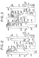
- Fig. 3 illustrates another embodiment of the present invention.
- the remaining liquid flashed in a flash tank 285 is introduced via a conduit 216 into a heat exchanger 206 and allowed to exchange heat with the bottom liquid of the ethylene oxide absorber.
- the bottom liquid of ethylene oxide stripper which departs from the heat exchanger 206 flows through a refrigerant vaporizer 289 of a heat pump and then passes through a cooler 217.
- Water may be introduced via a conduit 203a, an aqueous potassium hydroxide solution via a conduit 203b, and an anti-foam agent (water - soluble silicone emulsion) via a conduit 203c into the ethylene oxide absorber 202 jointly through a conduit 203.
- an anti-foam agent water - soluble silicone emulsion
- the refrigerant which has been vaporized in the refrigerant vaporizer 289 through heat exchange with the bottom liquid of the ethylene oxide stripper is forwarded via a conduit 290 to a refrigerant compressor 291 to be compressed therein and then forwarded via a conduit 292 to a refrigerant condenser 293, there to be condensed through transfer of its heat an external fluid.
- the condensed refrigerant is forwarded via a conduit 294 again to the refrigerant vaporizer 289.
- a conduit 299 is enabled to recover steam by circulating the water via a conduit 295 to a tank 297 and via a conduit 296 to the refrigerant condenser 293, and said water is supplied via a conduit 298 to a tank 297.
- the steam thus recovered can be effectively used as a heat source in the production step for ethylene oxide.
- This steam can be used in the ethylene oxide refiner.
- the reference numerals which are the sums of those of Fig. 2 each plus 100 denotes similar members.
- Fig. 4 illustrates another embodiment of the present invention.
- part of the bottom liquid of the stripper which contains substantially no ethylene oxide and has a temperature of 100 ° to 150°C is introduced via a conduit 314 and a conduit 315 to a flash tank 385, there to have the pressure thereof lowered to atmospheric pressure of a reduced pressure enough to generate a low-pressure vapor and lower the temperature of the solution.
- the low-pressure vapor generated in the flash tank 385 is forwarded via a conduit 386 to a vapor compressor 387, there to be compressed to a pressure slightly higher than the bottom pressure, 0.5 to 2.4 kg/cm 2 G, of the ethylene oxide stripper 311.
- the compressed vapor is forwarded via a conduit 386a to the vapor - phase part in the bottom of the ethylene oxide stripper 311.
- the remaining liquid which has been flashed in the flash tank 385 is forwarded via a conduit 316a to a heat exchanger 306, caused to exchange heat therein with the ethylene oxide-containing bottom liquid of the ethylene oxide absorber.
- the resultant liquid is introduced via a conduit 316b into a reboiler 358 of an ethylene oxide refiner 350 to be used as a heat source therein.
- the liquid is forwarded via a conduit 316c to a cooler 317.
- Via a conduit 321 water, an aqueous potassium hydroxide solution, and an anti - foam agent (water-soluble silicone emulsion) may be added and, via a conduit 303, introduced into the ethylene oxide absorber 302.
- the remaining absorbent liquid withdrawn via a conduit 314 from the bottom of the ethylene oxide stripper 311 is forwarded via a conduit 322 to the by - produced ethylene glycol evaporator (not shown).
- the ethylene oxide-containing vapor liberated through stripping from the top of the ethylene oxide stripper 311 is introduced via conduit 323 into a reboiler 360 of the ethylene oxide refiner 350 to be used as a heat source therein. Then, the resulting condensate and the uncondensed vapor is forwarded via a conduit 361 into a condenser 364 having cooling water circulated via a conduit 362 and a conduit 363 therein. The condensate is returned via a conduit 327 to the top of the ethylene oxide stripper 311 and the uncondensed vapor is introduced via a conduit 328 to a dehydrator 329.
- This bottom liquid of hydrator is heated either by heating a conduit 331 with a heating medium such as steam of Dowtherm (a product of the Dow Chemical Company) in the reboiler 330 of the dehydrator 329 or by directly introducing steam into the lower part of the dehydrator 329. From the bottom of the dehydrator 329, water containing substantially no ethylene oxide is withdrawn via a conduit 332.
- a heating medium such as steam of Dowtherm (a product of the Dow Chemical Company) in the reboiler 330 of the dehydrator 329 or by directly introducing steam into the lower part of the dehydrator 329.
- the vapor containing ethylene oxide is forwarded via a conduit 333 to a condenser 334 having cooling water or brine circulated through a conduit 335 and a conduit 336 therein. Part of the resulting condensate is returned via a conduit 337 to the top of the dehydrator 329.
- the uncondensed vapor in the condenser 334 is introduced via a conduit 339 to an ethylene oxide vent-scrubber (not shown).
- the other part of the condensate is introduced via a conduit 338 to a light ends stripper 340.
- the ethylene oxide vapor containing a more volatile component gas is forwarded via a conduit 343 to a condenser 344.
- the condensate is returned via a conduit 347 to the top of the light ends stripper 340.
- the uncondensed vapor is introduced via a conduit 348 to the ethylene oxide vent - scrubber (not shown) for recovery of ethylene oxide.
- the bottom liquid of the light ends stripper 340 is introduced via a conduit 349 to a refiner 350.
- the refiner 350 has two reboilers 360 and 358, so that the bottom liquid from the refiner 350 is introduced to both reboiler 360 and reboiler 358.
- One portion of the bottom liquid from the refiner 350 is heated in the reboiler 360 as stated previously, by the diffusate emanating from the top of the ethylene oxide stripper 311 and returned to the refiner 350.
- the diffusate is then introduced into a heat exchanger 364 and the condensate thereof is returned to the stripper 311 via conduit 327.
- Another portion of the bottom liquid from the refiner 350 is heated in the reboiler 358 by the liquid from the flash drum 385 via conduit 316b and the liquid is returned to an absorber 302 via conduit 316c.
- Both heated bottom liquids in both reboilers respectively are returned to the refiner 350.
- Both reboilers are different in a temperature, because the reboiler 360 is heated by the diffusate (vapor) from the stripper 311, so the temperature is high, while the reboiler 358 is heated by the liquid from the flash drum 385 after heat-exchanging at a heat exchanger 306, so the temperature is lower then the reboiler 360.
- the rectification is carried out with the bottom temperature of the ethylene oxide refiner 350 controlled in the range of 35 ° to 85 ° C and the bottom pressure of the ethylene oxide refiner in the range of 1.2 to 8.2 kg/cm 2 G.
- the ethylene oxide vapor having a top temperature of 29 ° to 81 ° C and a top pressure of 1 to 8 kg/cM 2 G is forwarded via a conduit 351 to an ethylene oxide condenser 352, for condensation of ethylene oxide.
- Part of the condensed ethylene oxide is returned via a conduit 356 to the top of the ethylene oxide refiner 350 and the other part thereof is withdrawn as ethylene oxide product via a conduit 357.
- the bottom liquid of the ethylene oxide refiner 350 is withdrawn via a conduit 367 when necessary for the separation of the heavey - duty portions of such high - boiling impurities as acetaldehyde and acetic acid.
- the reference numerals which are the sums of those of Fig. 2 each plus 200 denote similar members.
- Fig. 5 illustrates yet another embodiment of the present invention.
- the bottom liquid of the ethylene oxide stripper from a flash tank 485 which has been introduced to a reboiler 458 of a refiner and utilized as a heat source therein is introduced via a conduit 442a to a reboiler 441 of a light ends stripper 440 and used as a heat source for the light ends stripper and then returned via a conduit 442b to a cooler 417.
- the method of this embodiment is similar to that of Fig. 4.
- the reference numerals which are the sums of those of Fig. 4 each plus 100 denote similar members.
- Fig. 6 illustrates still another embodiment of the present invention.
- the liquid obtained by the flashing treatment in a flash tank 585 is forwarded to a heat exchanger 506 and then used as a heat source for a light ends stripper 540.
- this liquid is introduced via a conduit 516b into a reboiler 541 and utilized therein and then is forwarded via a conduit 516c to a cooler 517.
- the reference numerals which are the sums of those of Fig. 4 each plus 200 denote similar members.
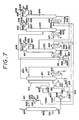
- Fig. 7 illustrates a further embodiment of the present invention.
- the liquid obtained by the flashing treatment in a flash tank 685 is passed through a heat exchanger 606 and then used as a joint heat source for an ethylene oxide refiner 650 and a light ends stripper 640.
- this liquid is supplied via a conduit 616c to a reboiler 658 and via a conduit 642a to a reboiler 641 and then forwarded invariably via a conduit 616e to a cooler 617.
- the reference numerals which are the sums of those of Fig. 4 each plus 300 denote similar members.
- the gas resulting from the catalytic gas-phase oxidation of ethylene with a molecular oxygen-containing gas in the presence of a silver catalyst and consequently containing ethylene oxide was introduced via the conduit 101 to the lower part of the tray type ethylene oxide absorber 102.
- An absorbent liquid having a temperature of 29.6 ° C and a pH of 6 and composed of 9.0% by weight of ethylene glycol, 3 ppm of an anti-foam agent (water - soluble silicone emulsion), and the balance of water was introduced via a conduit 103 into the upper part of the absorber 102 and brough into counterflow contact therein with the aforementioned gas, so as to allow the ethylene oxide present in the gas to be absorbed by the absorbent liquid.
- not less than 99% by weight of the ethylene oxide present in the gas was recovered.
- gases such gases as the ethylene, oxygen, carbon dioxide, inert gases (nitrogen, argon, methane, and ethane), aldehydes, and acidic substances which had escaped being absorbed were circulated via the conduit 104 to the absorption step for carbon dioxide gas and/or the oxidation step.
- the bottom liquid of the ethylene oxide absorber 102 was forwarded via the conduit 105, a heat exchanger 106, and a conduit 107 to a gas - liquid separation tank 108 and the more volatile component gas containing ethylene oxide and water was separated by a conduit 109.
- the absorbent liquid remaining after separation of the more volatile component gas by flashing was introduced via a conduit 110 to the upper part of ethylene oxide stripper 111 and was heated therein by supplying steam via a conduit 113 to a reboiler 112 of the stripper 111. Consequently, from the bottom of the ethylene oxide stripper 111, the bottom liquid of the stripper containing substantially no ethylene oxide was withdrawn via a conduit 114.
- Part of the liquid was introduced via a conduit 115 to a flash tank 185, there to effect drop of pressure to atmospheric pressure, a fall of the temperature of the solution.
- the low-pressure vapor generated in the flash tank 185 was forwarded via a conduit 186 to a vapor compressor 187 and compressed therein to a pressure by 0.1 Kg/cM 2 G higher than the bottom pressure, 0.5Kg/cm 2 G, of the stripper 111.
- the compressed vapor was forwarded via a conduit 186a into the vapor-phase part in the bottom of the stripper.
- the liquid remaining after the flashing treatment in the flash tank 185 was passed via a conduit 116 to the beat exchanger 106 and the cooler 117, admixed with water introduced via a conduit 103a an aqueous potassium hydroxide solution introduced via a conduit 103b, and an anti-foam agent (water-soluble silicone emulsion) introduced via a conduit 103C, and introduced via a conduit 103 into the absorber 102.
- water introduced via a conduit 103a an aqueous potassium hydroxide solution introduced via a conduit 103b
- an anti-foam agent water-soluble silicone emulsion
- part of the liquid obtained by flashing in a flash tank 285 was introduced via a conduit 216 to a heat exchanger 206, caused to exchange heat therein with the bottom liquid of the ethylene oxide absorber and introduced via a conduit 216a to a refrigerant vaporizer 289.
- the refrigerant which had been vaporized in the refrigerant evaporator 289 by the bottom liquid of the ethylene oxide stripper was forwarded via a conduit 290 to a refrigerant compressor 291 to be compressed therein.
- the compressed refrigerant was forwarded via a conduit 292 to a refrigerant condenser 293 and condensed therein through transfer of heat to an external fluid.
- the condensed refrigerant was sent via a conduit 294 to the refrigerant vaporizer 289 again.
- Table 2 shows collectively the conditions for continuous operation of this process.
- the gas formed by the catalytic gas - phase oxidation of ethylene with a molecular oxygen-containing gas in the presence of a silver catalyst and consequently containing ethylene oxide was introduced via a conduit 301 to the lower part of a tray type ethylene oxide absorber 302.
- An absorbent liquid having a temperature of 29.6 ° C and a pH of 6 and composed of 9.0 % by weight of ethylene glycol, 3 ppm of an anti-foam agent (water - soluble silicone emulsion), and the balance of water was introduced via a conduit 303 into the upper part of the ethylene oxide absorber 302 and brought into counterflow contact with the reaction product gas, with the result that the ethylene oxide present in the product gas was absorbed by the absorbent liquid.
- not less than 99% by weight of the ethylene oxide present in the product gas was recovered.
- the ethylene oxide absorber 302 From the top of the ethylene oxide absorber 302, the ethylene, oxygen, carbon dioxide, inert gases (nitrogen, argon, methane, and ethane), and impurities such as aldehydes and acidic substances which had escaped being absorbed, were circulated via a conduit 304 to the absorption step for carbon dioxide and/or the oxidation step.
- inert gases nitrogen, argon, methane, and ethane
- the bottom liquid of the ethylene oxide absorber 302 was sent via a conduit 305 to a heat exchanger 306 and caused to exchange heat therein with the bottom liquid of the ethylene oxide stripper and allowed to reach an elevated temperature 82.7 C.
- the hot liquid was forwarded via a conduit 307 to a gas - liquid separation tank 308. Consequently, a more volatile component gas containing ethylene oxide and water was separated.
- the absorbent liquid remaining after the separation of the more volatile cmponent gas by flashing was introduced via a conduit 310 to the upper part of an ethylene oxide stripper 311 having a top pressure of 0.4Kg/cm 2 G and a temperature of 87 C. It was caused to obtain ethylene oxide from the top of the ethylene oxide stripper by being heated with vapor supplied via a conduit 313 to a reboiler 312 of the ethylene oxide stripper 311.
- the bottom liquid containing substantially no ethylene oxide was withdrawn via a conduit 314.
- Part of the withdrawn bottom liquid was supplied via a conduit 315 to a flash tank 385 to generate low - pressure vapor and induce a fall of the temperature of the solution through drop of pressure to - 0.35 Kg/cm 2 G.
- the low - pressure vapor generated in the flash tank 385 was sent via a conduit 386 to a vapor compressor 387 and compressed therein to a pressure by 0.6Kg/cm 2 G higher than the bottom pressure, 0.5 Kg/cm 2 G, of the ethylene oxide stripper 311.
- the compressed vapor was introduced via a conduit 386a into the vapor-phase part in the bottom of the ethylene oxide stripper 311.
- the liquid remaining after the flashing treatment in the flash tank 385 was forwarded via a conduit 316a to the heat exchanger 306 and caused to exchange heat with the ethylene oxide-containing bottom liquid of the ethylene oxide absorber, forwarded via a conduit 316b to a reboiler 358 of an ethylene oxide refiner, then used as a heat soruce for the ethylene oxide refiner, forwarded via a conduit 316c to a cooler 317, admixed with water, an aqueous potassium hydroxide solution, and an anti - foam agent (water - soluble silicone emulsion ) introduced via a conduit 321, and introduced via a conduit 303 into the ethylene oxide absorber 302.
- the ethylene oxide-containing vapor obtained through diffusion from the top of the ethylene oxide stripper 311 was forwarded via a conduit 323 to a reboiler 360 of an ethylene oxide refiner 350 and used as a heat source therein. Then, the condensate and the uncondensed vapor were forwarded via a conduit 361 to a condenser 364 having cooling water circulated through a conduit 362 and a conduit 363 therein. The condensate was returned via a conduit 327 to the top of the ethylene oxide stripper 311 and the uncondensed vapor was introduced via a conduit 328 to a dehydrator 329.
- the bottom liquid of dehydrator was heated with a reboiler 330 of the dehydrator 329 by passing steam through a conduit 331 into the reboiler 330. From the bottom of the dehydrator 329, the water containing substantially no ethylene oxide was withdrawn via a conduit 332.
- the ethylene oxide - containing vapor was forwarded via a conduit 333 to a condenser 334 having brine circulated through a conduit 335 and a conduit 336 therein. Part of the condensate was returned via a conduit 337 to the top of the dehydrator 329.
- the uncondensed vapor in the condenser 334 was introduced via a conduit 339 to an ethylene oxide vent-scrubber (not shown).
- the other part of the condensate was introduced via a conduit 338 to a light ends stripper 340 which is of a packed type packed with pall rings possessing a pressure drop of not more than 5 mm Hg per theoretical step.
- the ethylene oxide vapor containing the more volatile component gas was forwarded via a conduit 343 to a condenser 344.
- the condensate was returned via a conduit 347 to the top of the light ends stripper 340 and the uncondensed vapor was introduced via a conduit 348 to the ethylene oxide vent-scrubber (not shown) for recovery of ethylene oxide.
- the bottom liquid of the light ends stripper 340 was introduced via a conduit 349 to an ethylene oxide refiner 350 which is of a packed type packed with pall ring possessing a pressure drop of not more than 5 mm Hg per theoretical step.
- the heating was carried out by supplying the diffusate from the top of the ethylene oxide stripper 311 to a reboiler 360 of the ethylene oxide refiner 350, by introducing the absorbent liquid for ethylene oxide via a conduit 316b to the reboiler 358 of the refiner 350.
- the distillation was carried out with the bottom temperature of the ethylene oxide refiner 350 at 45 ° C and the bottom pressure thereof at 2.0 Kg/cm 2 G.
- the ethylene oxide vapor having a top temperature of 39 ° C and a top pressure of 1.8kg/cm 2 G was forwarded via a conduit 351 to the ethylene oxide condenser 352 to condense ethylene oxide.
- Part of the condensed ethylene oxide was introduced via a conduit 356 to the top of the ethylene oxide refiner 350 and the other part was withdrawn as ethylene oxide product via a conduit 357.
- the uncondensed vapor in the ethylene oxide condenser 352 was introduced via a conduit 355 to the ethylene oxide vent - scrubber (not shown) for recovery of ethylene oxide.
- the bottom liquid of the ethylene oxide refiner 350 was withdrawn via a conduit 367 for the separation of heavy - duty components such as high - boiling impurities like acetaldehyde and acetic acid.
- Table 3 collectively shows the conditions for continuous operation of the process.
- Example 5 in a method similar to that of Example 3, by using a light ends stripper and an ethylene oxide refiner which were of tray types equipped ballast trays possessing a pressure drop of not more than 10 mm Hg per theoretical step, the bottom liquid of an ethylene oxide stripper was caused by a heat exchanger 406 to exchange heat with the liquid from an ethylene oxide absorber 402, the resulting liquid was introduced via conduits 416b and 416c to a reboiler 458 of an ethylene oxide refiner 450 and used in heating the liquid inside the refiner 450, the liquid was then introduced via a conduit 442a to a heater 441 of a light ends stripper 440 to heat the liquid in a light ends stripper 440, then, it was introduced via a conduit 442b and a cooler 417 and cooled thereby. The cooled liquid was circulated to the ethylene oxide absorber 402. In all the other respects, the method was similar to that of Example 3 . Table 4 shows collectively the conditions for continuous operation of
- the bottom liquid of the ethylene oxide stripper was caused by a heat exchanger 506 to exchange heat with the liquid from an ethylene oxide absorber 502.
- the resulting liquid was introduced via a conduit 516b to a reboiler 541 of the light ends stripper 540 and used as a heat source therefor.
- the liquid was sent via a conduit 516c to a cooler 517 and cooled thereby.
- the cooled liquid was circulated via a conduit 520 and a conduit 503 to the ethylene oxide absorber 502.
- the method was similar to that of Example 3.
- Table 5 shows collectively the conditions for continuous operation of the process.
- the bottom liquid of the ethylene oxide stripper was flashed in a flash tank 685 and then caused by a heat exchanger 606 to exchange heat with the liquid from the ethylene oxide absorber 602.
- the resulting liquid was parallely introduced via conduits 616c and 642a respectively to a reboiler 658 of an ethylene oxide refiner 650 and to a reboiler 641 of a light ends stripper 640 and used as a heat source therefor, then sent through conduits 616d and 642b via a conduit 616e to a cooler 617 and cooled therein, and circulated via conduits 620 and 603 to the ethylene oxide absorber 602.
- the method was similar to that of Example 3.
- the same procedures as the above were carried out, except that operation conditions of component parts were changed.
- Table 12 shows collectively the conditions for continuous operation of this process.
- the method of this invention since the vapor which is generated when the bottom liquid of the ethylene oxide stripper is flashed is separated from the flash drum, compressed by compression means to a pressure slightly higher than the bottom pressure of the ethylene oxide stripper, and introduced to the vapor - phase part in the bottom of the ethylene oxide stripper, there is manifested an effect of generously decreasing the amount of heat required for heating the ethylene oxide stripper. Further, by recovering heat from the liquid of the ethylene oxide stripper by means of a heat pump and utilizing the recovered heat as a heat source for the ethylene oxide refiner, saving of the energy consumed by the ethylene oxide refiner can be attained at the same time.
Landscapes
- Chemical & Material Sciences (AREA)
- Organic Chemistry (AREA)
- Epoxy Compounds (AREA)
- Organic Low-Molecular-Weight Compounds And Preparation Thereof (AREA)
Claims (12)
Applications Claiming Priority (4)
| Application Number | Priority Date | Filing Date | Title |
|---|---|---|---|
| JP60139175A JPH0662594B2 (ja) | 1985-06-27 | 1985-06-27 | エチレンオキシドの回収方法 |
| JP139175/85 | 1985-06-27 | ||
| JP145850/85 | 1985-07-04 | ||
| JP60145850A JPS6210076A (ja) | 1985-07-04 | 1985-07-04 | エチレンオキシドの回収方法 |
Publications (3)
| Publication Number | Publication Date |
|---|---|
| EP0207448A2 EP0207448A2 (fr) | 1987-01-07 |
| EP0207448A3 EP0207448A3 (en) | 1989-05-10 |
| EP0207448B1 true EP0207448B1 (fr) | 1993-05-19 |
Family
ID=26472065
Family Applications (1)
| Application Number | Title | Priority Date | Filing Date |
|---|---|---|---|
| EP86108722A Expired - Lifetime EP0207448B1 (fr) | 1985-06-27 | 1986-06-26 | Procédé pour la récupération d'oxyde d'éthylène |
Country Status (7)
| Country | Link |
|---|---|
| US (1) | US4875909A (fr) |
| EP (1) | EP0207448B1 (fr) |
| KR (1) | KR920003199B1 (fr) |
| CN (1) | CN1019270B (fr) |
| AU (1) | AU590888B2 (fr) |
| CA (1) | CA1284334C (fr) |
| DE (1) | DE3688444T2 (fr) |
Families Citing this family (38)
| Publication number | Priority date | Publication date | Assignee | Title |
|---|---|---|---|---|
| US4778567A (en) * | 1985-07-03 | 1988-10-18 | Nippon Shokubai Kagaku Kogyo Co. | Method for purification of ethylene oxide and recovery of heat thereof |
| AU591137B2 (en) * | 1985-07-03 | 1989-11-30 | Atochem | Method for purification of ethylene oxide |
| US5043461A (en) * | 1989-01-30 | 1991-08-27 | The Boc Group, Inc. | Process for the production of oxides |
| GB0020523D0 (en) * | 2000-08-18 | 2000-10-11 | Bp Chem Int Ltd | Process |
| US6533843B2 (en) * | 2001-06-05 | 2003-03-18 | Scientific Design Company, Inc. | Two stage flash for hydrocarbon removal |
| US6749668B2 (en) * | 2001-06-18 | 2004-06-15 | Degussa Ag | Process for the recovery of combustible components of a gas stream |
| PE20070158A1 (es) * | 2005-05-10 | 2007-03-02 | Shell Int Research | Proceso y dispositivo para recuperar oxido de etileno de un absorbente graso |
| US20070203348A1 (en) * | 2005-12-22 | 2007-08-30 | Bolk Jeroen W | Method Of Installing An Epoxidation Catalyst In A Reactor, A Method Of Preparing An Epoxidation Catalyst, An Epoxidation Catalyst, A Process For The Preparation Of An Olefin Oxide Or A Chemical Derivable From An Olefin Oxide, And A Reactor Suitable For Such A Process |
| US20070203352A1 (en) * | 2005-12-22 | 2007-08-30 | Bolk Jeroen W | Method Of Installing An Epoxidation Catalyst In A Reactor, A Method Of Preparing An Epoxidation Catalyst, An Epoxidation Catalyst, A Process For The Preparation Of An Olefin Oxide Or A Chemical Derivable From An Olefin Oxide, And A Reactor Suitable For Such A Process |
| US20070197808A1 (en) * | 2005-12-22 | 2007-08-23 | Bolk Jeroen W | Method Of Installing An Epoxidation Catalyst In A Reactor, A Method Of Preparing An Epoxidation Catalyst, An Epoxidation Catalyst, A Process For The Preparation Of An Olefin Oxide Or A Chemical Derivable From An Olefin Oxide, And A Reactor Suitable For Such A Process |
| US7459589B2 (en) * | 2005-12-22 | 2008-12-02 | Shell Oil Company | Process for the preparation of an alkylene glycol |
| US20070203349A1 (en) * | 2005-12-22 | 2007-08-30 | Bolk Jeroen W | Method Of Installing An Epoxidation Catalyst In A Reactor, A Method Of Preparing An Epoxidation Catalyst, An Epoxidation Catalyst, A Process For The Preparation Of An Olefin Oxide Or A Chemical Derivable From An Olefin Oxide, And A Reactor Suitable For Such A Process |
| US20070151451A1 (en) * | 2005-12-22 | 2007-07-05 | Rekers Dominicus M | Process for the cooling, concentration or purification of ethylene oxide |
| US20070213545A1 (en) * | 2005-12-22 | 2007-09-13 | Bolk Jeroen W | Method Of Installing An Epoxidation Catalyst In A Reactor, A Method Of Preparing An Epoxidation Catalyst, An Epoxidation Catalyst, A Process For The Preparation Of An Olefin Oxide Or A Chemical Derivable From An Olefin Oxide, And A Reactor Suitable For Such A Process |
| US20070197801A1 (en) * | 2005-12-22 | 2007-08-23 | Bolk Jeroen W | Method of installing an epoxidation catalyst in a reactor, a method of preparing an epoxidation catalyst, an epoxidation catalyst, a process for the preparation of an olefin oxide or a chemical derivable from an olefin oxide, and a reactor suitables for such a process |
| US20070203350A1 (en) * | 2005-12-22 | 2007-08-30 | Bolk Jeroen W | Method Of Installing An Epoxidation Catalyst In A Reactor, A Method Of Preparing An Epoxidation Catalyst, An Epoxidation Catalyst, A Process For The Preparation Of An Olefin Oxide Or A Chemical Derivable From An Olefin Oxide, And A Reactor Suitable For Such A Process |
| US20070154377A1 (en) * | 2005-12-22 | 2007-07-05 | Rekers Dominicus M | Process for the removal of combustible volatile contaminant materials from a process stream |
| US7704908B2 (en) * | 2005-12-22 | 2010-04-27 | Shell Oil Company | Method for reusing rhenium from a donor spent epoxidation catalyst |
| US7666369B2 (en) | 2006-09-29 | 2010-02-23 | Tyco Healthcare Group Lp | System and method for recycling sterilant gas |
| US8268238B2 (en) | 2006-09-29 | 2012-09-18 | Tyco Healthcare Group Lp | System and method for recycling sterilant gas |
| US20080154052A1 (en) * | 2006-12-20 | 2008-06-26 | Jeroen Willem Bolk | Method of installing an epoxidation catalyst in a reactor, a method of preparing an epoxidation catalyst, an epoxidation catalyst, a process for the preparation of an olefin oxide or a chemical derivable from an olefin oxide, and a reactor suitable for such a process |
| US20080154051A1 (en) * | 2006-12-20 | 2008-06-26 | Jeroen Willem Bolk | Method of installing an epoxidation catalyst in a reactor, a method of preparing an epoxidation catalyst, an epoxidation catalyst, a process for the preparation of an olefin oxide or a chemical derivable from an olefin oxide, and a reactor suitable for such a process |
| AR064958A1 (es) * | 2007-01-22 | 2009-05-06 | Shell Int Research | Procesos para la produccion de oxido de etileno y glicol de etileno |
| US7569710B1 (en) | 2008-02-23 | 2009-08-04 | Brian Ozero | Ethylene oxide recovery process |
| CN103463924B (zh) * | 2013-08-29 | 2016-01-27 | 张家港市三联化工科技有限公司 | 合成s-2-氯丙酸甲酯的尾气吸附装置 |
| CN104815535B (zh) * | 2015-04-07 | 2017-01-11 | 山西大同大学 | 一种含环氧乙烷的有机废气的再利用方法 |
| CN109422708B (zh) * | 2017-08-28 | 2021-03-30 | 中国石油化工股份有限公司 | 环氧乙烷纯化方法 |
| CN107473294B (zh) * | 2017-08-31 | 2024-01-26 | 上海晟兰石化工程技术有限公司 | 一种丙烯腈回收塔塔釜液的处理工艺及处理系统 |
| US10738020B2 (en) | 2017-11-22 | 2020-08-11 | Joseph D. Duff | Recovery of ethylene oxide from sterilization process |
| SG11202005095WA (en) * | 2017-11-30 | 2020-06-29 | China Petroleum & Chem Corp | Method and system for producing epoxyalkane |
| CN112055708B (zh) * | 2018-04-30 | 2024-04-02 | 科学设计有限公司 | 用浓缩的环氧乙烷溶液进行的环氧化方法 |
| TWI843724B (zh) | 2018-04-30 | 2024-06-01 | 美商科學設計有限公司 | 用於製備乙二醇的方法 |
| WO2019213032A1 (fr) | 2018-04-30 | 2019-11-07 | Scientific Design Company, Inc. | Procédé d'amélioration de la fabrication d'éthylène glycol |
| KR102731858B1 (ko) | 2018-04-30 | 2024-11-19 | 사이언티픽 디자인 컴파니 인코포레이티드 | 에틸렌 글리콜 제조를 위한 재순환 공정 |
| WO2020032279A1 (fr) * | 2018-08-10 | 2020-02-13 | 株式会社日本触媒 | Procédé de production d'oxyde d'éthylène et d'éthylène glycol |
| CN111116515B (zh) * | 2018-10-30 | 2022-11-04 | 中国石油化工股份有限公司 | 环氧烷烃回收方法 |
| CN113559540A (zh) * | 2020-04-29 | 2021-10-29 | 北京诺维新材科技有限公司 | 一种环氧乙烷的汽提方法和汽提装置 |
| CN120001200A (zh) * | 2023-11-16 | 2025-05-16 | 中国石油化工股份有限公司 | 含环氧化合物尾气的处理方法与处理装置 |
Family Cites Families (22)
| Publication number | Priority date | Publication date | Assignee | Title |
|---|---|---|---|---|
| US3174262A (en) * | 1965-03-23 | Chemical process and apparatus for recovery of ethylene oxide | ||
| US2711473A (en) | 1953-11-30 | 1955-06-21 | Standard Packaging Corp | Liquid heater |
| US2806552A (en) * | 1956-02-27 | 1957-09-17 | Phillips Petroleum Co | Absorption process |
| US3097215A (en) | 1960-04-08 | 1963-07-09 | Shell Oil Co | Recovery of hydrocarbon oxidation products |
| US3165539A (en) * | 1960-07-08 | 1965-01-12 | Halcon International Inc | Recovery of ethylene oxide from a liquid mixture thereof with normally gaseous impurities |
| US3217466A (en) * | 1962-05-22 | 1965-11-16 | Lummus Co | Recovery of ethylene oxide |
| US3357900A (en) * | 1965-05-17 | 1967-12-12 | American Cyanamid Co | Series flash distillation for recovery of hcn from aqueous cu-containing slurries |
| US3745092A (en) | 1971-01-11 | 1973-07-10 | Shell Oil Co | Recovery and purification of ethylene oxide by distillation and absorption |
| US3729899A (en) | 1971-06-23 | 1973-05-01 | Shell Oil Co | Recovery of ethylene oxide from admixed inert gaseous components |
| BE789308A (fr) | 1971-10-04 | 1973-03-27 | Shell Int Research | Terige oplossingen van etheenoxyde werkwijze voor het concentreren en zuiveren van wa |
| IT971365B (it) * | 1972-11-30 | 1974-04-30 | Sir Soc Italiana Resine Spa | Procedimento per il recupero dell ossido di etilene |
| US4028070A (en) * | 1974-04-11 | 1977-06-07 | Nippon Shokubai Kagaku Kogyo Co., Ltd. | Method of recovering ethylene oxide |
| US3964980A (en) | 1975-03-24 | 1976-06-22 | Halcon International, Inc. | Process for the recovery of ethylene oxide |
| IT1039745B (it) * | 1975-07-08 | 1979-12-10 | Sir Soc Italiana Resine Spa | Procedimento per la purificazione di eilende ossido |
| US4137129A (en) * | 1977-10-07 | 1979-01-30 | Uop Inc. | Fractionation process |
| US4184855A (en) * | 1977-12-29 | 1980-01-22 | Union Carbide Corporation | Process for CO2 removal |
| US4378977A (en) * | 1978-11-09 | 1983-04-05 | Linde Aktiengesellschaft | Removal of undesired gaseous components from hot waste gases |
| DE2943130A1 (de) * | 1978-11-09 | 1981-05-07 | Linde Ag, 6200 Wiesbaden | Verfahren zur entfernung unerwuenschter gasfoermiger bestandteile aus heissen abgasen |
| US4422903A (en) * | 1981-02-17 | 1983-12-27 | Raphael Katzen Associates International Inc. | Anhydrous ethanol distillation method and apparatus |
| IT1144657B (it) * | 1981-03-02 | 1986-10-29 | Snam Progetti | Procedimento per l'assorbimento isotermico dell'ossido di etilene mediante l'impiego di assorbitori a film |
| GB2137523B (en) * | 1983-03-31 | 1986-06-18 | Peter Spencer | Absorbing noxious gases |
| AU591137B2 (en) * | 1985-07-03 | 1989-11-30 | Atochem | Method for purification of ethylene oxide |
-
1986
- 1986-06-25 CA CA000512407A patent/CA1284334C/fr not_active Expired - Lifetime
- 1986-06-26 AU AU59269/86A patent/AU590888B2/en not_active Ceased
- 1986-06-26 EP EP86108722A patent/EP0207448B1/fr not_active Expired - Lifetime
- 1986-06-26 DE DE8686108722T patent/DE3688444T2/de not_active Expired - Fee Related
- 1986-06-27 CN CN86104909A patent/CN1019270B/zh not_active Expired
- 1986-06-27 KR KR1019860005200A patent/KR920003199B1/ko not_active Expired
-
1987
- 1987-12-01 US US07/127,488 patent/US4875909A/en not_active Expired - Lifetime
Also Published As
| Publication number | Publication date |
|---|---|
| AU590888B2 (en) | 1989-11-23 |
| EP0207448A3 (en) | 1989-05-10 |
| AU5926986A (en) | 1987-01-08 |
| CN1019270B (zh) | 1992-12-02 |
| EP0207448A2 (fr) | 1987-01-07 |
| US4875909A (en) | 1989-10-24 |
| KR920003199B1 (ko) | 1992-04-24 |
| KR870000316A (ko) | 1987-02-17 |
| CN86104909A (zh) | 1987-02-25 |
| DE3688444T2 (de) | 1993-08-26 |
| DE3688444D1 (de) | 1993-06-24 |
| CA1284334C (fr) | 1991-05-21 |
Similar Documents
| Publication | Publication Date | Title |
|---|---|---|
| US4875909A (en) | Method for recovery of ethylene oxide | |
| EP0207490B1 (fr) | Méthode pour la purification de l'oxyde d'éthylène | |
| JP2001316308A (ja) | エチレングリコールの製造方法 | |
| JP3901351B2 (ja) | アクロレインを含む気体流れの精製のためのプラント | |
| US9518036B2 (en) | Method for producing ethylene oxide | |
| TWI557119B (zh) | 環氧乙烷的製造方法 | |
| JP5828793B2 (ja) | エチレンオキシドの製造プロセスにおける炭酸ガスの回収方法 | |
| MXPA06010637A (es) | Utilizacion del calor de reaccion del acido acetico en otras plantas de procesamiento. | |
| KR102663736B1 (ko) | 에틸렌 옥시드 및 에틸렌 글리콜 생산 방법 | |
| JPH0676205B2 (ja) | 高純度二酸化炭素の回収方法 | |
| JPH0655734B2 (ja) | エチレンオキシドの回収方法 | |
| EP1636178B1 (fr) | Procede de preparation de caprolactame | |
| KR920001767B1 (ko) | 에틸렌옥사이드의 정제방법 | |
| TW593299B (en) | Recovery and purification of 3,4-epoxy-1-butene using water-miscible solvents | |
| JPH0625197B2 (ja) | エチレンオキシドの精製方法 | |
| JP2013082674A (ja) | プロピレンオキサイドの精製方法 | |
| EP1636179B1 (fr) | Procede de fabrication de caprolactame a partir du 6-amino-capronitrile impur contenant de la tetrahydroazepine | |
| JPH0655733B2 (ja) | エチレンオキシドの回収方法 | |
| JP3543447B2 (ja) | 二量化アルデヒドの製造方法 | |
| JP2013082675A (ja) | プロピレンオキサイドの回収方法 | |
| RU2785430C2 (ru) | Способы производства этиленоксида и этиленгликоля | |
| JPS6212770A (ja) | エチレンオキシドの精留方法 | |
| JP6522078B2 (ja) | エチレンオキシドの製造方法 | |
| JPS6330476A (ja) | エチレンオキシドの精製方法 | |
| JPS6216474A (ja) | エチレンオキシドの精製方法 |
Legal Events
| Date | Code | Title | Description |
|---|---|---|---|
| PUAI | Public reference made under article 153(3) epc to a published international application that has entered the european phase |
Free format text: ORIGINAL CODE: 0009012 |
|
| AK | Designated contracting states |
Kind code of ref document: A2 Designated state(s): BE DE FR GB IT NL SE |
|
| PUAL | Search report despatched |
Free format text: ORIGINAL CODE: 0009013 |
|
| AK | Designated contracting states |
Kind code of ref document: A3 Designated state(s): BE DE FR GB IT NL SE |
|
| 17P | Request for examination filed |
Effective date: 19890915 |
|
| 17Q | First examination report despatched |
Effective date: 19910716 |
|
| RAP3 | Party data changed (applicant data changed or rights of an application transferred) |
Owner name: ELF ATOCHEM S.A. Owner name: NIPPON SHOKUBAI KAGAKU KOGYO CO., LTD |
|
| RAP1 | Party data changed (applicant data changed or rights of an application transferred) |
Owner name: ELF ATOCHEM S.A. Owner name: NIPPON SHOKUBAI CO., LTD. |
|
| GRAA | (expected) grant |
Free format text: ORIGINAL CODE: 0009210 |
|
| AK | Designated contracting states |
Kind code of ref document: B1 Designated state(s): BE DE FR GB IT NL SE |
|
| REF | Corresponds to: |
Ref document number: 3688444 Country of ref document: DE Date of ref document: 19930624 |
|
| ITF | It: translation for a ep patent filed | ||
| ET | Fr: translation filed | ||
| RAP2 | Party data changed (patent owner data changed or rights of a patent transferred) |
Owner name: ELF ATOCHEM S.A. |
|
| NLT2 | Nl: modifications (of names), taken from the european patent patent bulletin |
Owner name: ELF ATOCHEM S.A. TE PUTEAUX, FRANKRIJK. |
|
| PLBE | No opposition filed within time limit |
Free format text: ORIGINAL CODE: 0009261 |
|
| STAA | Information on the status of an ep patent application or granted ep patent |
Free format text: STATUS: NO OPPOSITION FILED WITHIN TIME LIMIT |
|
| 26N | No opposition filed | ||
| NLS | Nl: assignments of ep-patents |
Owner name: ELF ATOCHEM S.A. TE PUTEAUX, FRANKRIJK. |
|
| REG | Reference to a national code |
Ref country code: FR Ref legal event code: TP |
|
| EAL | Se: european patent in force in sweden |
Ref document number: 86108722.9 |
|
| REG | Reference to a national code |
Ref country code: GB Ref legal event code: 732E |
|
| PGFP | Annual fee paid to national office [announced via postgrant information from national office to epo] |
Ref country code: GB Payment date: 19990607 Year of fee payment: 14 |
|
| PGFP | Annual fee paid to national office [announced via postgrant information from national office to epo] |
Ref country code: BE Payment date: 19990621 Year of fee payment: 14 |
|
| PGFP | Annual fee paid to national office [announced via postgrant information from national office to epo] |
Ref country code: NL Payment date: 19990622 Year of fee payment: 14 |
|
| PGFP | Annual fee paid to national office [announced via postgrant information from national office to epo] |
Ref country code: DE Payment date: 19990813 Year of fee payment: 14 |
|
| PG25 | Lapsed in a contracting state [announced via postgrant information from national office to epo] |
Ref country code: GB Free format text: LAPSE BECAUSE OF NON-PAYMENT OF DUE FEES Effective date: 20000626 |
|
| PG25 | Lapsed in a contracting state [announced via postgrant information from national office to epo] |
Ref country code: BE Free format text: LAPSE BECAUSE OF NON-PAYMENT OF DUE FEES Effective date: 20000630 |
|
| BERE | Be: lapsed |
Owner name: S.A. ELF ATOCHEM Effective date: 20000630 |
|
| PG25 | Lapsed in a contracting state [announced via postgrant information from national office to epo] |
Ref country code: NL Free format text: LAPSE BECAUSE OF NON-PAYMENT OF DUE FEES Effective date: 20010101 |
|
| GBPC | Gb: european patent ceased through non-payment of renewal fee |
Effective date: 20000626 |
|
| NLV4 | Nl: lapsed or anulled due to non-payment of the annual fee |
Effective date: 20010101 |
|
| PG25 | Lapsed in a contracting state [announced via postgrant information from national office to epo] |
Ref country code: DE Free format text: LAPSE BECAUSE OF NON-PAYMENT OF DUE FEES Effective date: 20010403 |
|
| PGFP | Annual fee paid to national office [announced via postgrant information from national office to epo] |
Ref country code: FR Payment date: 20010611 Year of fee payment: 16 |
|
| PGFP | Annual fee paid to national office [announced via postgrant information from national office to epo] |
Ref country code: SE Payment date: 20020624 Year of fee payment: 17 |
|
| PG25 | Lapsed in a contracting state [announced via postgrant information from national office to epo] |
Ref country code: FR Free format text: LAPSE BECAUSE OF NON-PAYMENT OF DUE FEES Effective date: 20030228 |
|
| REG | Reference to a national code |
Ref country code: FR Ref legal event code: ST |
|
| PG25 | Lapsed in a contracting state [announced via postgrant information from national office to epo] |
Ref country code: SE Free format text: LAPSE BECAUSE OF NON-PAYMENT OF DUE FEES Effective date: 20030627 |
|
| EUG | Se: european patent has lapsed | ||
| PG25 | Lapsed in a contracting state [announced via postgrant information from national office to epo] |
Ref country code: IT Free format text: LAPSE BECAUSE OF NON-PAYMENT OF DUE FEES;WARNING: LAPSES OF ITALIAN PATENTS WITH EFFECTIVE DATE BEFORE 2007 MAY HAVE OCCURRED AT ANY TIME BEFORE 2007. THE CORRECT EFFECTIVE DATE MAY BE DIFFERENT FROM THE ONE RECORDED. Effective date: 20050626 |