EP0207458B1 - Disjoncteur - Google Patents
Disjoncteur Download PDFInfo
- Publication number
- EP0207458B1 EP0207458B1 EP86108763A EP86108763A EP0207458B1 EP 0207458 B1 EP0207458 B1 EP 0207458B1 EP 86108763 A EP86108763 A EP 86108763A EP 86108763 A EP86108763 A EP 86108763A EP 0207458 B1 EP0207458 B1 EP 0207458B1
- Authority
- EP
- European Patent Office
- Prior art keywords
- arc
- rise
- conductor
- circuit breaker
- fixed
- Prior art date
- Legal status (The legal status is an assumption and is not a legal conclusion. Google has not performed a legal analysis and makes no representation as to the accuracy of the status listed.)
- Expired
Links
Images


Classifications
-
- H—ELECTRICITY
- H01—ELECTRIC ELEMENTS
- H01H—ELECTRIC SWITCHES; RELAYS; SELECTORS; EMERGENCY PROTECTIVE DEVICES
- H01H9/00—Details of switching devices, not covered by groups H01H1/00 - H01H7/00
- H01H9/30—Means for extinguishing or preventing arc between current-carrying parts
- H01H9/46—Means for extinguishing or preventing arc between current-carrying parts using arcing horns
Definitions
- the present invention relates generally to a circuit breaker, and particularly to a circuit breaker having an arc extinguisher and an arc runner which is disposed on both sides of fixed contact point, according to the pre-characterizing part of claim 1.
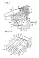
- FIG.3 is a partially sectional side view of a prior art circuit breaker as described in the Japanese patent application Sho 59-169391 (Japanese unexamined published patent application Sho 61-49338 published on 11.3.86), and FIG.3A is a perspective view showing a principal part of this prior art circuit breaker.
- the circuit breaker of the prior art comprises a fixed conductor 1 having a fixed contact point 1A on one end thereof, an arc runner 2 fixed to the fixed conductor 1, a moving conductor 4 having a moving contact point 4A on the moving end part, or in other words, near the moving end, of the moving conductor 4, and an arc extinguisher 5.
- the fixed conductor 1 has a curved part 1c consisting of an intermediate part 11a and a rise up part 11b.
- the upper end of the rise up part 11b is integrally connected to a power source side lead 1b.
- the fixed contact point 1A is electro-conductively fixed on an elevated holder part 1a of the fixed conductor 1.
- the elevated holder part 1a and the intermediate part 11a are formed integrally.
- the arc runner 2 comprises a fixing part 2B, an arc running part 2C and a folded part 2F connecting the above-mentioned two parts into an integral body.
- the arc running part 2C has a slot 2a wherein the fixed contact point 1A is disposed.
- the fixing part 2B of the arc runner 2 is electro-conductively fixed to the intermediate part 11a of the fixed conductor 1 by a rivet 3, spot-welding, or the like means.
- the moving conductor 4 is movably held by a known circuit breaker mechanism at the opposite end part to the fixed contact point 4A, which touches with and departs from the fixed contact point 1A.
- the arc extinguisher 5 comprises known plural deionization plates and is disposed in such a space S as being in front of the moving course of the moving contact point 4A to carry out known arc extinguishing action.
- the arc is driven to the far end tip part 2c of the arc runner 2, and is cut into pieces by the deionizer plates of the arc extinguisher 5.
- the above-mentioned circuit breaker has a problem that undesirable inverse arc-driving force in a direction of arrow C was induced by a stray magnetic flux induced by a current flowing in the direction of arrow B in the upright part 11b. And hence, intended quick shifting of the arc current from the arc path between the contact points 4a and 1a to the arc path between the arc runner 2 and the end tip 4c of the moving conductor 4 is obstracted, thereby lowering the circuit breaking ability.
- the present invention aims to provide an improved circuit breaker being capable of improving the circuit breaking ability.
- FIG.1 and FIG.1A show a principal part of a first embodiment of the present invention.
- the circuit breaker of the first embodiment comprises a fixed conductor 1 having a contact point 1A on one end thereof, an arc runner 2 fixed to the fixed conductor 1, a moving conductor 4 having a moving contact point 4A on its moving end part, or in other words near the moving end of the moving conductor 4, and an arc extinguisher 5.
- the circuit breaker in accordance with the present invention comprises a rise up member 2D, which is made of conductive substance, such as copper or iron, and the rise up member 2D is electro-conductively connected to the fixed conductor 1 by rivetting or spot-welding or the like means.
- the fixed conductor has a curved part 1c consisting of an intermediate part 11a and a rise up part 11b.
- the upper end of the rise up part 11b is integrally connected to a power source side lead 1b.
- the fixed contact point 1A is electro-conductively fixed on an elevated holder part 1a of the fixed conductor 1.
- the elevated holder part 1a and the intermediate part 11a are made integrally.
- the arc runner 2 comprises a fixing part 2B, an arc running part 2C and a folded part 2F connecting the above-mentioned two parts into an integral body.
- the arc running part 2C has a slot 2a wherein the fixed contact point 1A is disposed.
- the fixing part 2B of the arc runner 2 is electro-conductively fixed to the intermediate part 11a of the fixed conductor 1 by a rivet 3, spot-welding, or the like means.
- the rise up member 2D may be configurated integral to the arc runner 2 by extending the fixing part 2B and folding it upward to form the rise up part 2D, as shown in the example of FIG.1 and FIG.1A.
- the rivet 3 or spot-welding means is for fixing the fixing part 2B of the arc runner 2 to the intermediate part 11a of the fixed conductor 1.
- the above-mentioned rise up member 2D constitutes an arc retainer for retaining the arc there, thereby to prevent the arc from running excessively outside beyond the arc extinguisher 5.
- the moving conductor 4 is movably held by a known circuit breaker mechanism at the opposite end part to the fixed contact point 4A, which touches with and departs from the fixed contact point 1A to break and connect a circuit.
- the arc extinguisher 5 comprises known plural deionization plates and is disposed in such a space S as is in front of moving path of the moving contact point 4A to carry out known arc extinguishing action.
- the arc is driven to the far end tip part 2c of the arc runner 2, and is cut into many pieces by the deionizer plates of the arc extinguisher 5.
- the rise up member 2D of a conductive substance such as copper or iron is provided, being connected to the fixed conductor 1, the rise up member 2D serves as the arc retainer. Since the top face of the rise up member 2D has a substantially horizontal face 2d, the arc A which runs rightwards from the fixed contact point 1A on the arc runner part 2C finally jumps on the top face 2d of this arc retainer 2D, thereby forming the retention arc A1 as shown by the solid lines. Accordingly, undesirable excessive arc running to the end tip 2c of the arc runner 2C and subsequent shifting on the power source side lead 1b, which has been hitherto observed, is prevented. Hence, satisfactory arc extinguishing by the arc extinguisher 5 is achievable.
- the arc retainer 2D is preferably configurated such that the top edge 2d protrudes above a virtual plane which is an extension of the upper surface (arc running surface) near the end part 2c of the arc running part 2C.
- the undesirable electromagnetic effect by a large current which flows in the upright part 11b from the power source side 1b to the fixed contact point 1A, can be shielded. Therefore, no undesirable electromagnetic effect is given to the arc A0 which is between the fixed contact point 1A and the moving contact point 4A at the initial state of opening of the moving conductor 4. Accordingly, the arc A0 can be smoothly commuted from the arc path between the fixed contact point 1A and the moving contact point 4A to the runner arc path between the runner part 2C and end tip part 4c. And thereby, circuit breaking characteristic of the circuit breaker is satisfactorily improved.
- the ferromagnetic shield 2D can serve simultaneously as the arc retainer and also as the magnetic shield, when it is made of a ferromagnetic substance.
- the magnetic shield 2D is disposed in close proximity to the upright part 11b, the effect of magnetic shield becomes prominent.
- FIG.1, FIG.1A, FIG.2 and FIG.2A by forming the magnetic shield 2D in integral configuration with the arc runner 2, the effect of the arc retainer and the magnetic shield is obtainable, only by slight addition of the rise up member 2D to the fixing part 2B of the arc runner 2, and its manufacturing is easy and economical.
- the position of the top face 2d of the rise up member 2D should be protruding above the virtual plane of extension of the runner part 2C; whereas when the effect of the magnetic shield is mainly required, the top face 2d of the rise up part 2D may be offset from the virtual plane as shown in FIG.2 and FIG.2A.
- the rise up member 2D is made by continuously extending the fixing part 2B of the arc runner 2 and uprightly bending its end to form the rise up member 2D.
- the rise up member 2D may be produced as a separate piece from the arc runner 2 by separately rivetting or spot-welding it onto the fixed conductor 1.
Landscapes
- Arc-Extinguishing Devices That Are Switches (AREA)
- Breakers (AREA)
Claims (6)
- Disjoncteur comprenant :
un conducteur fixe (1) connecté par une extrémité à un côté source de courant ;
un point de contact fixe (1A) prévu à l'autre extrémité dudit conducteur fixe (1) ;
un conducteur de l'arc (2) qui est un conducteur ayant : une partie de fixation (2B) qui est fixée de manière électroconductrice à une partie intermédiaire (11a) dudit conducteur fixe (1), une partie conductrice de l'arc (2C), qui a une fente (2A) où est disposé ledit point de contact fixe (1A), et une partie repliée (2F) qui relie ladite partie de fixation (2B) et ladite partie conductrice de l'arc (2C) ;
un conducteur mobile (4) ayant un point de contact mobile (4A) à sa partie extrême mobile (4c) ; et
un organe dressé (2D) qui est un conducteur en un matériau ferromagnétique ayant : une partie de fixation (2B), qui est fixée de manière électroconductrice à ladite partie intermédiaire (11A), une partie dressée qui monte en s'étendant sensiblement dans une direction perpendiculaire par rapport à ladite partie intermédiaire (11a) de manière que son extrémité (2d) soit disposée en une position au-delà d'une extrémité (2c) de ladite partie conductrice de l'arc (2C) avec un espace donné d'air (g) entre eux,
caractérisé en ce que
ledit organe dressé (2D) protège magnétiquement un espace conducteur de l'arc d'une partie dressée (11b) du côté source de courant dudit conducteur fixe (1), qui se trouve derrière ledit organe dressé (2D), où ledit organe dressé (2D) est disposé très près de ladite partie dressée (11b) du côté source de courant dudit conducteur fixe (1). - Disjoncteur selon la revendication 1, où un angle aigu est défini entre ladite partie de fixation (2B) et ladite partie conductrice de l'arc (2C).
- Disjoncteur selon la revendication 1 ou 2, où
ledit organe dressé (2D) a une face extrême (2d) qui est dans une direction sensiblement tournée vers une extrémité (4c) dudit conducteur mobile (4) pendant l'ouverture dudit disjoncteur pour retenir un arc entre lesdites faces extrêmes (2d) de ladite extrémité (4c) à ladite ouverture. - Disjoncteur selon la revendication 3, où
ladite face extrême (2d) est disposée pour dépasser au-delà d'un plan vituel qui est une extension de la surface de ladite partie conductrice de l'arc (2C) à proximité de la partie extrême (2c). - Disjoncteur selon l'une quelconque des revendications 1 à 4, où
ledit organe dressé (2D) fait corps avec ledit conducteur de l'arc (2) en formant lesdites parties de fixation (2B) des deux organes en une partie. - Disjoncteur selon l'une quelconque des revendications 1 à 5, où
ledit conducteur fixe (1) a une partie courbée (1c) et
ledit point de contact fixe (1A) est prévu en un emplacement qui est sur la surface supérieure de ladite partie mobile (1c) et qui est éloigné dudit organe dressé (2D).
Applications Claiming Priority (4)
| Application Number | Priority Date | Filing Date | Title |
|---|---|---|---|
| JP10200785 | 1985-07-02 | ||
| JP102008/85 | 1985-07-02 | ||
| JP10200885U JPS629338U (fr) | 1985-07-02 | 1985-07-02 | |
| JP102007/85 | 1985-07-02 |
Publications (3)
| Publication Number | Publication Date |
|---|---|
| EP0207458A2 EP0207458A2 (fr) | 1987-01-07 |
| EP0207458A3 EP0207458A3 (en) | 1989-05-31 |
| EP0207458B1 true EP0207458B1 (fr) | 1992-03-04 |
Family
ID=26442760
Family Applications (1)
| Application Number | Title | Priority Date | Filing Date |
|---|---|---|---|
| EP86108763A Expired EP0207458B1 (fr) | 1985-07-02 | 1986-06-27 | Disjoncteur |
Country Status (2)
| Country | Link |
|---|---|
| US (1) | US4689588A (fr) |
| EP (1) | EP0207458B1 (fr) |
Families Citing this family (11)
| Publication number | Priority date | Publication date | Assignee | Title |
|---|---|---|---|---|
| US5313031A (en) * | 1990-12-28 | 1994-05-17 | Mitsubishi Denki Kabushiki Kaisha | Electric switch gear with improved stationary contact configuration |
| FR2714520B1 (fr) * | 1993-12-24 | 1996-01-19 | Telemecanique | Appareil électrique interrupteur à contacts séparables. |
| JP3099690B2 (ja) * | 1995-08-03 | 2000-10-16 | 富士電機株式会社 | 回路遮断器 |
| FR2788164B1 (fr) * | 1998-12-30 | 2001-02-16 | Schneider Electric Ind Sa | Appareillage electrique de coupure dont un organe de contact est muni d'une fente |
| RU2149475C1 (ru) * | 1999-06-01 | 2000-05-20 | Закрытое акционерное общество "ЗЭТА" | Дугогасительный элемент |
| US6300586B1 (en) * | 1999-12-09 | 2001-10-09 | General Electric Company | Arc runner retaining feature |
| US7551050B2 (en) * | 2006-09-22 | 2009-06-23 | Rockwell Automation Technologies, Inc. | Contactor assembly with arc steering system |
| US7716816B2 (en) * | 2006-09-22 | 2010-05-18 | Rockwell Automation Technologies, Inc. | Method of manufacturing a switch assembly |
| US8947181B2 (en) * | 2012-11-15 | 2015-02-03 | Eaton Corporation | Arc runner assembly and circuit interrupter |
| FR3027728B1 (fr) * | 2014-10-22 | 2017-12-08 | Socomec Sa | Dispositif de coupure d'arc electrique |
| CN208240528U (zh) * | 2018-04-19 | 2018-12-14 | 施耐德电气工业公司 | 静触头组件和相应的开关触头 |
Family Cites Families (6)
| Publication number | Priority date | Publication date | Assignee | Title |
|---|---|---|---|---|
| DE1260000B (de) * | 1966-07-04 | 1968-02-01 | Wtz Elektroapp Dresden Wissens | Lichtbogenkammer fuer elektrische Schuetze kleinerer Stromstaerken |
| FR2378344A1 (fr) * | 1977-01-25 | 1978-08-18 | Telemecanique Electrique | Piece de soufflage |
| KR860002080B1 (ko) * | 1982-01-28 | 1986-11-24 | 카다야마히도 하지로 | 전력 개폐장치 |
| EP0117288B1 (fr) * | 1982-11-10 | 1988-03-02 | Mitsubishi Denki Kabushiki Kaisha | Interrupteur avec moyen d'extinction d'arc |
| US4628163A (en) * | 1983-12-07 | 1986-12-09 | Mitsubishi Denki Kabushiki Kaisha | Power switch |
| FR2569304B1 (fr) * | 1984-08-15 | 1990-12-28 | Mitsubishi Electric Corp | Interrupteur de circuit |
-
1986
- 1986-06-27 EP EP86108763A patent/EP0207458B1/fr not_active Expired
- 1986-07-02 US US06/881,258 patent/US4689588A/en not_active Expired - Fee Related
Also Published As
| Publication number | Publication date |
|---|---|
| EP0207458A2 (fr) | 1987-01-07 |
| US4689588A (en) | 1987-08-25 |
| EP0207458A3 (en) | 1989-05-31 |
Similar Documents
| Publication | Publication Date | Title |
|---|---|---|
| KR100304150B1 (ko) | 회로차단기의아아크소멸장치 | |
| US4689588A (en) | Circuit breaker | |
| KR900007273B1 (ko) | 회로 차단기 | |
| CA1085437A (fr) | Disjoncteur a barrette amelioree | |
| US4612427A (en) | Switch | |
| JP2562867B2 (ja) | 開閉器 | |
| JPH0454650Y2 (fr) | ||
| JPS62285325A (ja) | 開閉器 | |
| JPH0797459B2 (ja) | 開閉器 | |
| JPS63108623A (ja) | 開閉器 | |
| JPS62285324A (ja) | 開閉器 | |
| JPS63264829A (ja) | 開閉器 | |
| JPS59103229A (ja) | 開閉器 | |
| JPH0677418B2 (ja) | 開閉器 | |
| JPH11232980A (ja) | 電磁接触器の可動接触子 | |
| JPH0810570B2 (ja) | 接点装置 | |
| JPH0447925B2 (fr) | ||
| JPH0447926B2 (fr) | ||
| JPS59103221A (ja) | 開閉器 | |
| JPS59103224A (ja) | 開閉器 | |
| JPS63146311A (ja) | 開閉器 | |
| JPS62219419A (ja) | 開閉器 | |
| JPH03230434A (ja) | 開閉器 | |
| JPS6376216A (ja) | 回路しや断器 | |
| JPH0664961B2 (ja) | 開閉器 |
Legal Events
| Date | Code | Title | Description |
|---|---|---|---|
| PUAI | Public reference made under article 153(3) epc to a published international application that has entered the european phase |
Free format text: ORIGINAL CODE: 0009012 |
|
| AK | Designated contracting states |
Kind code of ref document: A2 Designated state(s): CH DE FR GB IT LI |
|
| PUAL | Search report despatched |
Free format text: ORIGINAL CODE: 0009013 |
|
| AK | Designated contracting states |
Kind code of ref document: A3 Designated state(s): CH DE FR GB IT LI |
|
| 17P | Request for examination filed |
Effective date: 19890925 |
|
| 17Q | First examination report despatched |
Effective date: 19900906 |
|
| GRAA | (expected) grant |
Free format text: ORIGINAL CODE: 0009210 |
|
| AK | Designated contracting states |
Kind code of ref document: B1 Designated state(s): CH DE FR GB IT LI |
|
| REF | Corresponds to: |
Ref document number: 3684044 Country of ref document: DE Date of ref document: 19920409 |
|
| ITF | It: translation for a ep patent filed | ||
| ET | Fr: translation filed | ||
| PLBE | No opposition filed within time limit |
Free format text: ORIGINAL CODE: 0009261 |
|
| STAA | Information on the status of an ep patent application or granted ep patent |
Free format text: STATUS: NO OPPOSITION FILED WITHIN TIME LIMIT |
|
| 26N | No opposition filed | ||
| PGFP | Annual fee paid to national office [announced via postgrant information from national office to epo] |
Ref country code: FR Payment date: 19950609 Year of fee payment: 10 |
|
| PGFP | Annual fee paid to national office [announced via postgrant information from national office to epo] |
Ref country code: GB Payment date: 19950616 Year of fee payment: 10 |
|
| PGFP | Annual fee paid to national office [announced via postgrant information from national office to epo] |
Ref country code: DE Payment date: 19950617 Year of fee payment: 10 |
|
| REG | Reference to a national code |
Ref country code: GB Ref legal event code: 746 Effective date: 19950523 |
|
| PGFP | Annual fee paid to national office [announced via postgrant information from national office to epo] |
Ref country code: CH Payment date: 19950623 Year of fee payment: 10 |
|
| REG | Reference to a national code |
Ref country code: FR Ref legal event code: D6 |
|
| ITPR | It: changes in ownership of a european patent |
Owner name: OFFERTA DI LICENZA AL PUBBLICO |
|
| PG25 | Lapsed in a contracting state [announced via postgrant information from national office to epo] |
Ref country code: GB Effective date: 19960627 |
|
| PG25 | Lapsed in a contracting state [announced via postgrant information from national office to epo] |
Ref country code: LI Effective date: 19960630 Ref country code: CH Effective date: 19960630 |
|
| REG | Reference to a national code |
Ref country code: CH Ref legal event code: PL |
|
| GBPC | Gb: european patent ceased through non-payment of renewal fee |
Effective date: 19960627 |
|
| PG25 | Lapsed in a contracting state [announced via postgrant information from national office to epo] |
Ref country code: FR Effective date: 19970228 |
|
| PG25 | Lapsed in a contracting state [announced via postgrant information from national office to epo] |
Ref country code: DE Effective date: 19970301 |
|
| REG | Reference to a national code |
Ref country code: FR Ref legal event code: ST |
|
| PG25 | Lapsed in a contracting state [announced via postgrant information from national office to epo] |
Ref country code: IT Free format text: LAPSE BECAUSE OF NON-PAYMENT OF DUE FEES;WARNING: LAPSES OF ITALIAN PATENTS WITH EFFECTIVE DATE BEFORE 2007 MAY HAVE OCCURRED AT ANY TIME BEFORE 2007. THE CORRECT EFFECTIVE DATE MAY BE DIFFERENT FROM THE ONE RECORDED. Effective date: 20050627 |