EP0207817A2 - Verbindungsstück für eine perkutane Zugangsvorrichtung - Google Patents
Verbindungsstück für eine perkutane Zugangsvorrichtung Download PDFInfo
- Publication number
- EP0207817A2 EP0207817A2 EP19860400960 EP86400960A EP0207817A2 EP 0207817 A2 EP0207817 A2 EP 0207817A2 EP 19860400960 EP19860400960 EP 19860400960 EP 86400960 A EP86400960 A EP 86400960A EP 0207817 A2 EP0207817 A2 EP 0207817A2
- Authority
- EP
- European Patent Office
- Prior art keywords
- valve
- connection
- tubular body
- connection head
- tubes
- Prior art date
- Legal status (The legal status is an assumption and is not a legal conclusion. Google has not performed a legal analysis and makes no representation as to the accuracy of the status listed.)
- Granted
Links
- 239000012530 fluid Substances 0.000 claims abstract description 102
- 210000004369 blood Anatomy 0.000 claims abstract description 48
- 239000008280 blood Substances 0.000 claims abstract description 48
- 238000009826 distribution Methods 0.000 claims abstract description 10
- 238000004891 communication Methods 0.000 claims description 20
- 230000004087 circulation Effects 0.000 claims description 18
- 239000007788 liquid Substances 0.000 claims description 13
- 238000013519 translation Methods 0.000 claims description 13
- 238000009795 derivation Methods 0.000 claims 1
- 238000005192 partition Methods 0.000 claims 1
- 238000011012 sanitization Methods 0.000 description 20
- 208000031968 Cadaver Diseases 0.000 description 13
- 230000006978 adaptation Effects 0.000 description 12
- 239000000463 material Substances 0.000 description 8
- 210000004379 membrane Anatomy 0.000 description 8
- 239000012528 membrane Substances 0.000 description 8
- 238000004500 asepsis Methods 0.000 description 7
- 238000010586 diagram Methods 0.000 description 7
- 238000002347 injection Methods 0.000 description 7
- 239000007924 injection Substances 0.000 description 7
- NOESYZHRGYRDHS-UHFFFAOYSA-N insulin Chemical compound N1C(=O)C(NC(=O)C(CCC(N)=O)NC(=O)C(CCC(O)=O)NC(=O)C(C(C)C)NC(=O)C(NC(=O)CN)C(C)CC)CSSCC(C(NC(CO)C(=O)NC(CC(C)C)C(=O)NC(CC=2C=CC(O)=CC=2)C(=O)NC(CCC(N)=O)C(=O)NC(CC(C)C)C(=O)NC(CCC(O)=O)C(=O)NC(CC(N)=O)C(=O)NC(CC=2C=CC(O)=CC=2)C(=O)NC(CSSCC(NC(=O)C(C(C)C)NC(=O)C(CC(C)C)NC(=O)C(CC=2C=CC(O)=CC=2)NC(=O)C(CC(C)C)NC(=O)C(C)NC(=O)C(CCC(O)=O)NC(=O)C(C(C)C)NC(=O)C(CC(C)C)NC(=O)C(CC=2NC=NC=2)NC(=O)C(CO)NC(=O)CNC2=O)C(=O)NCC(=O)NC(CCC(O)=O)C(=O)NC(CCCNC(N)=N)C(=O)NCC(=O)NC(CC=3C=CC=CC=3)C(=O)NC(CC=3C=CC=CC=3)C(=O)NC(CC=3C=CC(O)=CC=3)C(=O)NC(C(C)O)C(=O)N3C(CCC3)C(=O)NC(CCCCN)C(=O)NC(C)C(O)=O)C(=O)NC(CC(N)=O)C(O)=O)=O)NC(=O)C(C(C)CC)NC(=O)C(CO)NC(=O)C(C(C)O)NC(=O)C1CSSCC2NC(=O)C(CC(C)C)NC(=O)C(NC(=O)C(CCC(N)=O)NC(=O)C(CC(N)=O)NC(=O)C(NC(=O)C(N)CC=1C=CC=CC=1)C(C)C)CC1=CN=CN1 NOESYZHRGYRDHS-UHFFFAOYSA-N 0.000 description 6
- 230000002421 anti-septic effect Effects 0.000 description 4
- 238000000502 dialysis Methods 0.000 description 4
- 239000000806 elastomer Substances 0.000 description 4
- 229920001971 elastomer Polymers 0.000 description 4
- 210000002615 epidermis Anatomy 0.000 description 4
- 238000007789 sealing Methods 0.000 description 4
- 102000004877 Insulin Human genes 0.000 description 3
- 108090001061 Insulin Proteins 0.000 description 3
- 230000023555 blood coagulation Effects 0.000 description 3
- 210000004204 blood vessel Anatomy 0.000 description 3
- 230000015271 coagulation Effects 0.000 description 3
- 238000005345 coagulation Methods 0.000 description 3
- 210000004207 dermis Anatomy 0.000 description 3
- 229940079593 drug Drugs 0.000 description 3
- 239000003814 drug Substances 0.000 description 3
- 229940125396 insulin Drugs 0.000 description 3
- 238000000034 method Methods 0.000 description 3
- 239000002504 physiological saline solution Substances 0.000 description 3
- 210000001519 tissue Anatomy 0.000 description 3
- 241000894006 Bacteria Species 0.000 description 2
- 239000003146 anticoagulant agent Substances 0.000 description 2
- 229940127219 anticoagulant drug Drugs 0.000 description 2
- 238000009835 boiling Methods 0.000 description 2
- OVXZVDMCQPLHIY-QXGOIDDHSA-L calcium;4-[[(2r)-2,4-dihydroxy-3,3-dimethylbutanoyl]amino]butanoate Chemical compound [Ca+2].OCC(C)(C)[C@@H](O)C(=O)NCCCC([O-])=O.OCC(C)(C)[C@@H](O)C(=O)NCCCC([O-])=O OVXZVDMCQPLHIY-QXGOIDDHSA-L 0.000 description 2
- 230000007797 corrosion Effects 0.000 description 2
- 238000005260 corrosion Methods 0.000 description 2
- 239000000645 desinfectant Substances 0.000 description 2
- 210000003717 douglas' pouch Anatomy 0.000 description 2
- 230000000694 effects Effects 0.000 description 2
- 230000006870 function Effects 0.000 description 2
- 239000002184 metal Substances 0.000 description 2
- 239000000825 pharmaceutical preparation Substances 0.000 description 2
- 229940127557 pharmaceutical product Drugs 0.000 description 2
- 238000012545 processing Methods 0.000 description 2
- 238000010408 sweeping Methods 0.000 description 2
- 238000011144 upstream manufacturing Methods 0.000 description 2
- OKTJSMMVPCPJKN-UHFFFAOYSA-N Carbon Chemical compound [C] OKTJSMMVPCPJKN-UHFFFAOYSA-N 0.000 description 1
- 229920000049 Carbon (fiber) Polymers 0.000 description 1
- 244000000626 Daucus carota Species 0.000 description 1
- 235000002767 Daucus carota Nutrition 0.000 description 1
- HTTJABKRGRZYRN-UHFFFAOYSA-N Heparin Chemical compound OC1C(NC(=O)C)C(O)OC(COS(O)(=O)=O)C1OC1C(OS(O)(=O)=O)C(O)C(OC2C(C(OS(O)(=O)=O)C(OC3C(C(O)C(O)C(O3)C(O)=O)OS(O)(=O)=O)C(CO)O2)NS(O)(=O)=O)C(C(O)=O)O1 HTTJABKRGRZYRN-UHFFFAOYSA-N 0.000 description 1
- 208000034189 Sclerosis Diseases 0.000 description 1
- 239000004809 Teflon Substances 0.000 description 1
- 229920006362 Teflon® Polymers 0.000 description 1
- 241000897276 Termes Species 0.000 description 1
- 239000000654 additive Substances 0.000 description 1
- 230000000996 additive effect Effects 0.000 description 1
- 238000004873 anchoring Methods 0.000 description 1
- 239000003242 anti bacterial agent Substances 0.000 description 1
- 229940088710 antibiotic agent Drugs 0.000 description 1
- 230000010100 anticoagulation Effects 0.000 description 1
- 210000001367 artery Anatomy 0.000 description 1
- 239000002473 artificial blood Substances 0.000 description 1
- 230000017531 blood circulation Effects 0.000 description 1
- 230000005587 bubbling Effects 0.000 description 1
- 229910052799 carbon Inorganic materials 0.000 description 1
- CREMABGTGYGIQB-UHFFFAOYSA-N carbon carbon Chemical compound C.C CREMABGTGYGIQB-UHFFFAOYSA-N 0.000 description 1
- 239000004917 carbon fiber Substances 0.000 description 1
- 239000011203 carbon fibre reinforced carbon Substances 0.000 description 1
- 239000002131 composite material Substances 0.000 description 1
- 238000013461 design Methods 0.000 description 1
- 230000006866 deterioration Effects 0.000 description 1
- 230000001627 detrimental effect Effects 0.000 description 1
- 239000012153 distilled water Substances 0.000 description 1
- 239000013536 elastomeric material Substances 0.000 description 1
- 238000001631 haemodialysis Methods 0.000 description 1
- 230000000322 hemodialysis Effects 0.000 description 1
- 229960002897 heparin Drugs 0.000 description 1
- 229920000669 heparin Polymers 0.000 description 1
- 238000002513 implantation Methods 0.000 description 1
- 208000014674 injury Diseases 0.000 description 1
- 238000003780 insertion Methods 0.000 description 1
- 230000037431 insertion Effects 0.000 description 1
- 230000010354 integration Effects 0.000 description 1
- 230000001926 lymphatic effect Effects 0.000 description 1
- 229940126601 medicinal product Drugs 0.000 description 1
- 230000008520 organization Effects 0.000 description 1
- 239000002245 particle Substances 0.000 description 1
- 239000004033 plastic Substances 0.000 description 1
- 229920001343 polytetrafluoroethylene Polymers 0.000 description 1
- 239000004810 polytetrafluoroethylene Substances 0.000 description 1
- 239000011148 porous material Substances 0.000 description 1
- 238000002360 preparation method Methods 0.000 description 1
- 230000002035 prolonged effect Effects 0.000 description 1
- 238000010926 purge Methods 0.000 description 1
- 238000005096 rolling process Methods 0.000 description 1
- 239000000565 sealant Substances 0.000 description 1
- 210000002966 serum Anatomy 0.000 description 1
- 239000000243 solution Substances 0.000 description 1
- 238000004659 sterilization and disinfection Methods 0.000 description 1
- 230000008733 trauma Effects 0.000 description 1
- 230000000472 traumatic effect Effects 0.000 description 1
- 229940124549 vasodilator Drugs 0.000 description 1
- 239000003071 vasodilator agent Substances 0.000 description 1
- 210000003462 vein Anatomy 0.000 description 1
- 238000012795 verification Methods 0.000 description 1
- XLYOFNOQVPJJNP-UHFFFAOYSA-N water Chemical compound O XLYOFNOQVPJJNP-UHFFFAOYSA-N 0.000 description 1
Images





Classifications
-
- A—HUMAN NECESSITIES
- A61—MEDICAL OR VETERINARY SCIENCE; HYGIENE
- A61M—DEVICES FOR INTRODUCING MEDIA INTO, OR ONTO, THE BODY; DEVICES FOR TRANSDUCING BODY MEDIA OR FOR TAKING MEDIA FROM THE BODY; DEVICES FOR PRODUCING OR ENDING SLEEP OR STUPOR
- A61M39/00—Tubes, tube connectors, tube couplings, valves, access sites or the like, specially adapted for medical use
- A61M39/02—Access sites
- A61M39/0247—Semi-permanent or permanent transcutaneous or percutaneous access sites to the inside of the body
-
- A—HUMAN NECESSITIES
- A61—MEDICAL OR VETERINARY SCIENCE; HYGIENE
- A61M—DEVICES FOR INTRODUCING MEDIA INTO, OR ONTO, THE BODY; DEVICES FOR TRANSDUCING BODY MEDIA OR FOR TAKING MEDIA FROM THE BODY; DEVICES FOR PRODUCING OR ENDING SLEEP OR STUPOR
- A61M39/00—Tubes, tube connectors, tube couplings, valves, access sites or the like, specially adapted for medical use
- A61M39/02—Access sites
- A61M39/0247—Semi-permanent or permanent transcutaneous or percutaneous access sites to the inside of the body
- A61M2039/0258—Semi-permanent or permanent transcutaneous or percutaneous access sites to the inside of the body for vascular access, e.g. blood stream access
-
- A—HUMAN NECESSITIES
- A61—MEDICAL OR VETERINARY SCIENCE; HYGIENE
- A61M—DEVICES FOR INTRODUCING MEDIA INTO, OR ONTO, THE BODY; DEVICES FOR TRANSDUCING BODY MEDIA OR FOR TAKING MEDIA FROM THE BODY; DEVICES FOR PRODUCING OR ENDING SLEEP OR STUPOR
- A61M39/00—Tubes, tube connectors, tube couplings, valves, access sites or the like, specially adapted for medical use
- A61M39/02—Access sites
- A61M39/0247—Semi-permanent or permanent transcutaneous or percutaneous access sites to the inside of the body
- A61M2039/027—Semi-permanent or permanent transcutaneous or percutaneous access sites to the inside of the body having a particular valve, seal or septum
-
- A—HUMAN NECESSITIES
- A61—MEDICAL OR VETERINARY SCIENCE; HYGIENE
- A61M—DEVICES FOR INTRODUCING MEDIA INTO, OR ONTO, THE BODY; DEVICES FOR TRANSDUCING BODY MEDIA OR FOR TAKING MEDIA FROM THE BODY; DEVICES FOR PRODUCING OR ENDING SLEEP OR STUPOR
- A61M39/00—Tubes, tube connectors, tube couplings, valves, access sites or the like, specially adapted for medical use
- A61M39/02—Access sites
- A61M39/0247—Semi-permanent or permanent transcutaneous or percutaneous access sites to the inside of the body
- A61M2039/0276—Semi-permanent or permanent transcutaneous or percutaneous access sites to the inside of the body for introducing or removing fluids into or out of the body
-
- A—HUMAN NECESSITIES
- A61—MEDICAL OR VETERINARY SCIENCE; HYGIENE
- A61M—DEVICES FOR INTRODUCING MEDIA INTO, OR ONTO, THE BODY; DEVICES FOR TRANSDUCING BODY MEDIA OR FOR TAKING MEDIA FROM THE BODY; DEVICES FOR PRODUCING OR ENDING SLEEP OR STUPOR
- A61M39/00—Tubes, tube connectors, tube couplings, valves, access sites or the like, specially adapted for medical use
- A61M39/02—Access sites
- A61M39/0247—Semi-permanent or permanent transcutaneous or percutaneous access sites to the inside of the body
- A61M2039/0282—Semi-permanent or permanent transcutaneous or percutaneous access sites to the inside of the body with implanted tubes connected to the port
Definitions
- the present invention relates to a removable fluid exchange system, connectable to an irremovable device for percutaneous passage of fluids and atraumatic access to a fluid circuit, such as for example a blood or lymphatic circuit in a living organism.
- the invention relates more particularly to the head for connection to the atraumatic access device, implanted in the living organism, and its device for supplying fluids.
- the fluids that can be exchanged with a living organism are the blood but also pharmaceutical products such as insulin, antibiotics, vasodilators. Hemodialysis is an important case of blood exchange concerned by the system of the invention.
- All these fluids are extracted or injected into the living organism by means of an irremovable atraumatic access device, which is constituted by a valve system establishing at will a communication between the interior and the exterior of the living organism. .
- an irremovable atraumatic access device which is constituted by a valve system establishing at will a communication between the interior and the exterior of the living organism. .
- the implantation of such an atraumatic access device is justified by the trauma and sclerosis of living tissues that the repetition of injections by hypodermic needles creates when repeated care is compulsory.
- Devices for atraumatic access to a circuit internal to the organism are known. Most have in common to include a body, part of which is in direct connection with the body's fluid circuit, and part of which, isolated from the previous one by a valve, is in relation to the exterior of the organization. This second part constitutes a well for access to the network of fluids of the organism, such as blood, although this example does not constitute a limit to the application of the invention; it crosses the dermis, emerges at the level of the epidermis, and is, outside the periods during which exchanges of fluid are practiced, blocked by any means impermeable to liquids and bacteria.
- a valve formed either by a membrane extensible, either by a membrane which can be pierced by a needle, or by a ball or any mechanical valve, or by a rotary barrel, or even by the frustoconical body of a "carrot" tap.
- the antiseptic products used in manual asepsis are poorly rinsed by the rinsing products, for example inside the ends of the tubes, or in certain concave parts of the access shaft.
- Injecting or exchanging fluids with a living organism is therefore a delicate operation, presenting risks, and costly because it is carried out by highly qualified personnel.
- connection head connected by at least two tubes to its device for supplying fluids, - even connected to a treatment device, such as a hemodialyzer or an insulin injector for example.
- connection head to the atraumatic access device under non-aseptic conditions, then to practice asepsis, rinsing and debubbling, without breaking the asepsis in the aseptic zone, by means of commands external to this aseptic zone, commands which can be manual but are preferably automated.
- This head for connection to the atraumatic access device to the blood circuit.
- This head comprises a cylinder coaxial with the access shaft and pierced longitudinally by at least two pipes, this cylinder being provided with at least one degree of freedom and moving by longitudinal translation in a base fixed on the atraumatic access device.
- a first position of the cylinder in which it is distant from the valve, there is a free passage for the fluids between the end of the cylinder and the valve, which allows the circulation of external fluids to sanitize, rinse and debub the tubes , the access shaft, in particular the inner walls, and the surface of the valve.
- the cylinder is furthermore provided, at its end close to the valve, with means suitable for opening this valve. These means are designed to interrupt the passage of fluids between the two pipes when said means are in contact with the valve.
- the cylinder In a second position of the cylinder, in contact with the valve, the cylinder opens the valve, and establishes the circulation of fluids between the living organism and at least one pipe drilled in the cylinder without any part having been returned to the air. The parts which have been sanitized therefore remain sanitized.
- the cylinder is moved relative to the body of the connection head by mechanical, fluidic (air or liquid) or electrical means.
- connection head and of the fluid supply device is designed to avoid any cavity, in order to prevent blood coagulation when this liquid is concerned.
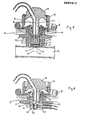
- Figure 1 shows the sectional view of a first embodiment of a removable connection head according to the invention, mounted on a known atraumatic access device, described in patent application No. 84 05141 which has been filed April 2, 1984 by the plaintiff.
- the percutaneous passage is implanted in the organism, under the dermis 1 and the epidermis 2. It essentially comprises a bypass tee, the two aligned parts of which form a tube 3, at the ends of which are fixed short flexible artificial blood sutures respectively to a vein and an artery. All this in the non-limiting case of the arteriovenous shunt.
- the third part of the tee forms a hollow body 4, which connects the surface of the epidermis 2 to the tube 3 traversed by the blood.
- the hollow body 4 is integral with a ring 5, provided with at least one collar.
- the ring 5 is made of carbon fibers impregnated with carbon, which gives it a porous structure: the tissues colonizing the pores of the ring 5 ensure the fixation of the percutaneous passage in the body, thus making it irremovable.
- the valve which controls the exchange of blood or fluids between the interior of the living organism and the exterior is here constituted by a body 6, in the form of a piston inside the hollow body 4, with which it provides a good sealing.
- This piston 6 is made of elastomeric material, and is fixed by one of its ends in the hollow body 4, while its other end, closed, is at the wall of the tube 3, but does not penetrate into the tube 3 when the valve is closed.
- the internal wall of the hollow body 4 obstructs two openings 22 and 23 made in the cylindrical wall of the piston 6.
- valve To open the valve, it is necessary to deform the elastomer piston 6, by lengthening it. Its end close to the tube 3 then penetrates therein, which has the effect of releasing the openings 22 and 23, and of establishing a circulation of blood or of fluids between the blood vessels, via the tube 3, and outside the body.
- Appropriate means make it possible to separate the flows, and to use one opening, for example 22, for extracting blood, and the other opening, 23 in this case, for reinjecting blood and / or pharmaceutical liquids.
- the valve is shown open in FIG. 2.
- the hollow body 4 finally comprises, on the side of its end external to the body, a thread which makes it possible to fix either a plug when the percutaneous passage is unused, or a connection head when it is used for exchanges of fluids with the blood network.
- the percutaneous passage therefore has an access well, constituted by the interior of the hollow body 4 and of the piston 6: this access well must be disinfected and rinsed before the blood treatment operation.
- This is one of the functions fulfilled by the connection head according to the invention shown in FIG. 1.
- This head essentially comprises a base 7 which can be fixed to the hollow body 4 of the percutaneous passage. All known mechanical fixing means can be used to fix the base 7 to the body 4, provided that they offer good sealing and a marked position of the base relative to the body, but a thread is the preferred method as being the least traumatic for the patient and the one who exerts the least effort on the percutaneous passage.
- This base includes on its periphery a collar which is used to screw it into the hollow body 4, and, in its central part, an additional thickness pierced in its center and coaxially with the hollow body 4.
- This passage is machined with precision, so that 'it constitutes a guide cylinder 8.
- it has an inside diameter equal to the inside diameter of the elastomer piston 6.
- a tubular body 9 which can move according to at least one degree of freedom, along the axis common to the hollow body 4, the piston 6 and the guide cylinder 8.
- This tubular body 9 is preferably pierced longitudinally along a diameter, of at least two channels 20 and 21. Indeed, even in the case where the percutaneous passage is used to only inject a product into the blood, a second channel is necessary to ensure circulation of the sanitizing and rinsing liquids, as well as boiling, during the preliminary operations.
- Channels 20 and 21 communicate at one end of the tubular body 9 with the treatment equipment via tubes 10 and 11. They open at the other end of the tubular body 9. Said end carries means for operating the valve 6, under the double condition of allowing free circulation of the fluids between the channels 20 and 21 when the valve is closed, and of isolating the same channels when the valve is open. These means vary according to the type of valve used.
- the means of opening consists of a projection 19, integral with the tubular body 9.
- This projection 19 has a length - measured along the axis of movement of the tubular body 9 - substantially equal to the diameter of the openings 22 and 23 of the elastomeric piston 6, so as to allow a regular flow of blood between the openings 22 and 23 and the channels 20 and 21, respectively, without risk of blood clotting in a cavity not swept by the blood flow, as shown in Figure 2.
- the projection 19 is formed, in this case elastomeric valve, by a portion of the tubular body 9 forming a blade along a diameter perpendicular to the diameter carrying the two channels 20 and 21.
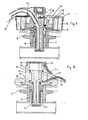
- Figures 1 and 2 show this blade according to its thickness, while Figure 3 shows it according to its width, that is to say in the axis of the two openings 22 and 23.
- connection head according to the invention is easily understood, with reference to FIGS. 1, 2 and 3.
- the tubular body 9 is in a position remote from the valve 6: to simplify the language, this position will be called the "high" position.
- This position will be called the "high" position.
- the valve is therefore closed. It is then possible to introduce a tube, for example, a sanitizing fluid, then to rinse by means of distilled water or physiological saline. The bubbling is done simultaneously, and all these fluids, as well as the bubbles, are extracted by the second tube, 11 in this case. All the parts which were not aseptic, and which will subsequently be in contact with the blood, are thus sanitized.
- the tubular body 9 has undergone a translation along its axis: it is in contact with the valve 6, which it extends. This position will be called the "low" position.
- the means by which the tubular body 9 has undergone a translation will be explained later.
- the valve being open, the openings 22 and 23 of the piston 6 are in communication with the channels 20 and 21, respectively, while the blade 19 seals with the bottom and the internal wall of the piston 6, as shown in FIG. 3.
- the blood can leave the percutaneous passage for example through the opening 22 and the channel 20, and be reinjected, after treatment, through the channel 21 and the opening 23.
- the tubular body 9 is brought back to the high position, which closes the valve 6 and interrupts the blood exchange. All of the tubes and the connection head can then be swept away from the blood, and washed with suitable fluids since the communication between the channels 20 and 21 is restored. After rinsing, at the end of the treatment, the connection head is unscrewed, and the percutaneous passage is blocked by a threaded plug.
- FIG. 5 represents a form of adaptation of the connection head according to the invention to a second type of known percutaneous passage valve.
- This valve consists of a thick elastomeric membrane 34, held against the wall of the blood bypass tube 3 by means of a sleeve 47, concentric with the hollow body 4, and a threaded ring 48.
- the membrane 34 is pierced with 'at least two series of slots, in stars, made along axes 35 and 36. In the absence of any constraint, the lips of the slots close, and the membrane 34 is tight, at the low pressures considered: the valve is closed .
- FIG. 5 shows the valve in the closed position, and the connection head in the high position.
- the tubes come into position 43 - 44 shown in dotted lines.
- connection head always includes a base 7, which can be fixed on the blood bypass tee and an extra thickness part 8 forming a guide cylinder, in which a tubular body 9 moves longitudinally drilled by two channels 20 and 21.
- the tubes 37 and 38 which form an integral part of the valve, are fixed in the channels 20 and 21, by any suitable means.
- the means which makes it possible to open the valve consists of the cylindrical body 9 itself, which pushes the tubes 37 and 38 through the membrane 34.
- the means which ensures the interruption of the circulation of fluids, between the channels 20 and 21, when the valve is open, consists of the planar lower end of the cylindrical body 9, which comes into contact with the planar surface of the membrane 34.
- connection head In the high position, with the valve closed, the antiseptic and rinsing fluids sweep and bubble the outer tubes, a first channel 20, exiting through the openings 39, 40, sweep the interior volume to the sleeve 47, and exit through the channel 21 , via openings 41 and 42. All surfaces are therefore sanitized and rinsed.
- the valve is open, without any part being released to the air, by a translation towards the position bottom of the cylindrical body 9: the blood can then leave the body for example through the openings 39, 40, the tube 37 and the channel 20, and be reinjected after treatment through the channel 21, the tube 38 and the openings 41, 42.
- the case of FIG. 5 requires a precise orientation of the part 9.
- the tubes 37 and 38 must pass exactly through the axes 35 and 36. This is achieved by means of the groove 45 and the lug 46.
- FIG. 6 represents another adaptation of the connection head according to the invention to a third type of percutaneous passage with a single channel, intended for example to inject a drug into the body at regular intervals, such as insulin.
- a collar 5 made of carbon-carbon composite, fixes under the dermis 1 and the epidermis 2 a hollow body 50, the bottom of which comprises a valve closed by a ball 51, pushed against its seat by a spring 52.
- This valve normally closed in the absence of any external constraint, leads to a pipe 53 connected to a blood vessel for example.
- the hollow body 50 includes, like the hollow body 4 located on the blood diversion tees, a thread which makes it possible to fix either a plug or a connection head.
- connection head always has the same structure which will no longer be detailed: base 7 and guide cylinder 8, tubular body 9 drilled longitudinally by two channels 20 and 21.
- the valve operating means is, as in the cases of the preceding figures, constituted by a projection 19, integral with the tubular body 9.
- the material which forms this projection completely surrounds a channel, for example 21, so that the latter is extended compared to the other channel.
- this projection 19 is partially in line with the ball 51: when the cylindrical body 9 is in the low position, the projection pushes the ball 51 and the spring 52 and the valve is open.
- the means which interrupts the circulation of fluids between the channels 20 and 21 is also the projection 19 which surrounds one of the two channels, for example 21.
- the channel 21 is longer than the channel 20, and ends on a flat surface and parallel to the surface of the bottom of the hollow body 50.
- FIGS. 1, 2 and 3 a first mechanical and manual means of longitudinal translation of the cylindrical body 9 is shown.
- This comprises, on the side of its end external to the living organism, a part 12 of a shape adapted to ensure the connection of the internal channels 20 and 21 with external tubes 10 and 11, by means of two metal end pieces.
- This first piece 12 of connection between tubes which is therefore integral with the cylindrical body 9 and, moreover, machined from the same block of material, comprises, on its circumference of larger diameter, a thread to which corresponds an operating nut 13.
- the operating nut 13 has a fixed position, relative to the longitudinal axis of the connection head, because it rests on the base 7 and that a washer or circlip 15 prevents it from translating along this axis.
- the length of the thread of the operating nut 13 is equal to the length of the possible translation of the cylindrical body 9, without deterioration of the valve 6 of elastomer.
- Another washer or circlip 16 prevents the connecting piece 12 from coming out of the thread.
- any mechanical means other than that shown in Figures 1 to 3 belongs to the field of the invention.
- the translational movement towards the so-called high position (valve closed) can be created by a coil spring, bearing on the opposite faces of the base 7 and of the connection piece 12, while the movement of translation to the low position (valve open) results from the action of a cam bearing on a stirrup which replaces the operating nut 13, and counteracts the action of the spring, by pushing on the connection piece 12.
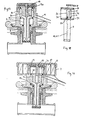
- FIG. 7 shows another means of actuating the connection head according to the invention. It is an electric motor which is preferably controlled by a sequencer of an apparatus for the automation of the processing operations.
- connection head is, in this case, slightly different in shape, and it supports, on its outer ring, a stator 28 of an electric motor, supplied by conductive wires by means of a connector 32.
- the operating nut 13 also has a suitable shape and it is integral with a rotor 27, forming, with the stator 28, the electric motor.
- the thread carried by the operating nut 13 is in this case a smaller pitch than the pitch of the mechanical means, in order to serve as a reduction so that the translational movement is not sudden.
- connection piece 12 is of the same type as that of the mechanical means, but its thread is of course adapted to that of the operating nut 13.
- connection piece 12 Two electrical contacts 29 and 30, placed at the end of travel of the connection piece 12, control the movement of the cylindrical body 9: when the connection piece crushes one of these contacts 29 or 30, it therefore interrupts the passage of the electric current in the motor 27 + 28, which is of course with a double direction of rotation.
- the limit switch 30 in the upper position can for example be carried by the cover 31 of the motor housing.
- The. rolling bearing of the rotor 13 + 27 can be very rudimentary and constituted by the friction of the part 13 in Teflon PTFE on the metal part 7.
- a ball bearing could be used in the same place.
- FIG. 8 represents a second embodiment of the connection head according to the invention which is also used in FIGS. 11, 12, 13, 14, 15 and 16. This FIG. 8 describes an actuation by pressure of fluids (air or liquids).
- connection head always comprises a base 7, necessary for fixing the head on the percutaneous passage, but the guide cylinder 8 is in this case integral with a cylinder 71 of the fluid actuator.
- the tubular body 9 is itself integral with a piston 70, which moves in the cylinder 71 of the actuator, closed by a cover 79.
- the working fluids - air or liquids - are introduced through pipes 90 and 91 and act, respectively, between the upper face of the piston 70 and the cover 79, the threading of which comprises a sealant, and between the lower face of the piston 70 and the upper face of the guide cylinder 8.
- FIG. 9 represents the tubular body 9, a part of the valve body 6 made of elastomer and a part of the guide cylinder 8.
- the latter forms a cylinder in soft friction contact with the tubular body 9.
- two cylindrical recesses 63 and 64 which are in communication, at their first end, with the channels 20 and 21, respectively, and at their second end with the outer tubes 10 and 11 respectively.
- the length of the grooves 63 and 64 is equal to the length of the translation of the tubular body 9, and their section is in agreement with the section of the channels 20 and 21, or of the tubes 10 and 11, so as to have no resistance the passage of blood.
- FIG. 10 represents a variant of this method of connection by grooves, but, while in the example of FIG. 9, the tubular body 9 has a united external wall and the cylindrical recesses are hollowed out in the guide cylinder 8, according to this variant, it is the guide cylinder 8 which has a united internal wall, and the cylindrical recesses 59 and 60 are hollowed out in the tubular body 9. Seals 61 and 62 provide sealing between the parts through which the blood passes and the outside of the connection head.
- the circular recesses 59, 60, 63, 64 in the piston or the cylinder could be grooves parallel to the axis of the piston but that, in this case, there would have to be a immobilization in rotation of the type of the sliding lug 78 FIG. 8.
- Figures 9 and 10 are in fact generalization figures. In reality, it is not recommended that the cylindrical recesses 59 and 60 or 63 and 64 are toric and coaxial with the tubular body 9, as this risks causing poor sweeping by the fluid passing through them, between the orifice of a channel. , 20 or 21, and the orifice of a tube, 10 or 11, and coagulation of stagnant blood.
- FIG. 11 shows that the grooves 74-76 and 75-77 do not completely surround the tubular body 9. On the other hand, they are at the same level and preferably diametrically opposite.
- Figure 12 shows the U-shape of a groove.
- Each groove 74-76 or 75-77 breaks down into a longitudinal part 74, at the base of which opens a channel, for example, then a transverse part 79, which communicates with a second longitudinal part 76.
- the two parts 74 and 76 have a length equal to the translation length of the cylindrical body 9.
- the outer tube 10 for the groove 75-77 and the tube 11 for the groove 74-76 open into grooves 77 and 76 respectively.
- the external tube 11 opens out in the lower part of the groove 76: the sanitizing fluid and the rinsing fluid sweeping all of the drains 74, 79, 76, and boiling them .
- the tube 11 opens, see FIG. 12, in the upper part of the groove 76 in Il ': the blood circulates in the grooves 74 and 79.
- the groove 76 in this case constitutes a cul-de-sac, but this does not present any drawback since the last operation before introducing blood was to rinse with physiological saline: the groove 76 is therefore filled with physiological saline, without danger for the organism and not risking coagulation.
- This groove shape explains and justifies the shape of the tubular body and of its connection piece 70, in FIG. 8, provided with a fluidic actuator or in FIGS. 11 to 16.
- FIG. 13 also represents, like FIG. 8, a connection head according to the invention in the second embodiment, but, in the case of FIG. 13, the actuation mode is mechanical instead of being hydraulic.
- a axial, manual or automated mechanical actuator This comprises an actuating nut 80, provided with a threaded pin 83 which cooperates with a thread in the connection part 70.
- a cover screwed in FIG. 71 immobilizes the actuating nut 80 longitudinally by means of a flange located on the base of the threaded rod 83.
- This rod 83 is welded to the nut 80 after having trapped the cover. It is screwed onto the part 71 using passage holes not shown on the top of the nut 80.
- FIG. 14 shows another adaptation of the same connection head to an electric actuator. The head is this time in the low position, valve open.
- the electric motor is in all respects comparable to the motor of FIG. 7, but the rotor 27 acts directly on the threaded axis 83.
- the stroke of the tubular body 9 is stopped when one of the electric contacts - not shown - is actuated by one or the other flat face of the piston 70, in the regions 88 or 89 for example which are recesses containing these electrical contacts.
- connection head according to the invention also includes safety devices intended to prevent any false maneuvering detrimental to the living organism. Their presentation requires returning to the previous figures.
- Figures 1 to 4 show a valve position safety. Since the elastomeric valve 6 is inside the percutaneous passage and hidden by the connection head of the invention, it is not seen whether the valve is in the closed position or, following an incident, blocked in open or even broken position. In order to avoid the injection of sanitizing fluids into the living organism, a safety device indicates the position of the valve.
- This security is composed of a feeler finger 92, which crosses without friction the tubular body 9 and is in permanent contact with the end face 17 of the piston of the valve 6. This contact is established under the effect of the thrust of a spring 96 which, at the head of the feeler finger 92, bears on a plug fixed to the connection head 12 on the one hand, and on a washer 93, provided with an index 94, secured to the feeler finger 92 on the other hand .
- the force of the spring 96 is calibrated so as not to open the valve by its push.
- the length of the rod 92 is such that the index 94 does not touch the top of the part 12: the sanitizing fluid can then be circulated without danger.
- This mechanical security can be replaced by an electrical security in the case where, as in FIG. 7, the actuator is an electric motor.
- This electrical safety comprises parts common with mechanical safety: feeler finger 92, washer 93, spring 96, but an electrical contact 33 makes it possible to know the position of the finger 92.
- the washer 93 In normal service, when the tubular body 9 is in the high position, and the valve 6 closed, the washer 93 must be halfway. If it is at the end of its travel, in the low position, and overwrites the electrical contact 33, this means that the valve 6 is accidentally open: a simple logic circuit which combines the contact 33 (position of the valve 6), the contact 30 ( position of the tubular body 9) and a solenoid valve on the sanitizing fluid circuit prohibits circulating this sanitizing fluid.
- Figures 15 and 16 show a safety device directly installed on the inlet circuit for sanitizing fluids. This security is particularly well suited when the actuator of the connection head is a fluidic actuator, comprising a piston 70.
- the sanitizing fluid before arriving at one of the external tubes, 10 and 11, passes through a bypass which is only open when the tubular body 9 is in the high position, therefore in the asepsis-rinse-bubble position.
- the sanitizing fluid arrives through a tube 98, for example which passes through the cylinder 71 of the actuator, and it leaves, under the same conditions, through another tube 99.
- the groove 97 allows the circulation of the fluids between the two pipes 98 and 99.
- valve open the groove 97 is no longer opposite the orifices 96, and the wall of the piston 70 hermetically seals them: the circulation of the sanitizing fluid is impossible.
- the tubular body 9 comprises at least two channels 20 and 21 - the other holes for feeler finger, screw, anti-rotation finger are not channels for circulation of fluids - and the figures represent only two, so as not to obscure the drawings.
- one or more additive channels are drilled in the tubular body 9. These channels can be used, for example, to inject anticoagulants or drugs at the same time as the blood is reinjected into the organism after treatment.
- One of the characteristic aspects of the invention is to guarantee an efficient circulation of various fluids not only in order to sanitize the irremovable percutaneous passage system before the start of a treatment, but also in order to completely sweep the tubes and cavities , so that traces of disinfectant or air bubbles do not remain in the circuit when treatment begins.
- connection head is necessarily associated with a so-called initial part, which belongs to the field of the invention, located between the treatment device - for example a dialyzer - and the connection head.
- This initial part is constituted by a fluid distributor device, a characteristic of which is - as for the connection head - that it does not have a volume which cannot be scanned by a moving fluid.
- FIG. 17 represents a very simplified diagram of a treatment system, comprising a connection head 100, mounted on a percutaneous passage 101 implanted in a living organism, a distributor box 103 + 104 and an apparatus for treatment or generation of fluid 102.
- the distributor box must have two separate parts, each of which is connected to one of the two outer tubes 10 and 11 of the connection head.
- the part 103 of the distributor box is joined by the connection "a" to the tube 10 and corresponds to the introduction of fluids into the connection head 100, while the part 104 is joined, by the connection "b", to the tube 11 and corresponds to the evacuation of the fluids coming from the connection head 100.
- the two tubes 10 and 11 located downstream of the distributor box 103 + 104 correspond to a plurality of tubes located upstream. These tubes, joined to the housing by the connections "c, d, ... i, j", are traversed by the various fluids delivered or absorbed by the treatment apparatus 102: disinfectant liquid, blood serum, medicinal products etc. It is therefore important that the internal volume of each part 103 + 104 of the distributor housing is, like the connection head, sanitized and unblocked before treatment, and does not have any dead volume, which cannot be scanned by a fluid.
- FIG. 18 is shown a cavity 103, forming a half of the distributor housing, and between a part 105 and a plate 109.
- the part 105 is machined, so that there are closed a plurality of chambers 106, each closed on the side of the cavity 103 by a valve 107, and supplied with fluid by a pipe orifice 108.
- the surface of the cavity 103, closed by the valves 107 and the surface of the part 105 does not have any part which is not swept by the fluids.
- the valves 107 correspond to the connections "c, d, e, f" of FIG. 17, and the free orifice 110 of the cavity 103 is connected to an external tube, 10, of the connection head 100.
- the fluids reaching the cavity 103 by one of the valves or valves c to f can, depending on the time considered for a complex treatment, such as renal dialysis for example, either arrive at c and leave at a towards the connection head 100, either to be interrupted or to arrive at c and leave at d, e or f to accompany a fluid arriving at a.
- a complex treatment such as renal dialysis for example
- valves 107 are operated from the outside, either manually, or by mechanical, electrical or fluid automation: their longitudinal movement makes it possible to open or close a valve.
- the dispenser box includes fixing, connection or sealing means which are not shown so as to simplify the figure.
- connection head The role of the housings 103 and 104 and its integration into the system comprising the connection head will appear even more clearly if we consider that the various asepsis, rinsing, debubbling and possible anticoagulation operations linked to the problem of connection from an external network to an internal network to a living organism must be able to be carried out in the simplest, most flexible, most precise and fastest possible way.
- the ideal location for the housing 103 + 104 will therefore be in the immediate vicinity of the connection head 100, although this remark in no way limits the supply.
- the irremovable percutaneous passage 101 is implanted on the arm of a patient, the connection head 100 being fixed on it, the housing 103 + 104 will be fixed on this same arm with a strap.
- the tubes 10 and 11 connecting the head 100 to the housing 103 + 104 will necessarily be made of a fairly flexible material so that the mechanical forces, if not negligible, caused by the connection to the housings 103 and 104 of the large bundle of the pipe and of wires coming from the apparatus. heavy 102 cannot be transmitted to the connection head.
- the presence of the housing 103 + 104 on the patient's body also facilitates the operation of the valves "a” to "j" which are fixed there in the case where they are manually controlled.
- connection head in the case where an assembly apparatus for a complex operation such as renal dialysis is partially or totally automated, the use of a connection head according to the invention, provided with a confirmed fluid or electrical control with the use, in the immediate vicinity, of a box 103 + 104 according to the invention itself comprising fluid or electrical controls constitutes a set of essential provisions which completes the set of automated components contained in the processing device 102.
Landscapes
- Health & Medical Sciences (AREA)
- Heart & Thoracic Surgery (AREA)
- Life Sciences & Earth Sciences (AREA)
- Animal Behavior & Ethology (AREA)
- Public Health (AREA)
- Pulmonology (AREA)
- Engineering & Computer Science (AREA)
- Anesthesiology (AREA)
- Biomedical Technology (AREA)
- Hematology (AREA)
- Biophysics (AREA)
- General Health & Medical Sciences (AREA)
- Gastroenterology & Hepatology (AREA)
- Veterinary Medicine (AREA)
- Infusion, Injection, And Reservoir Apparatuses (AREA)
- External Artificial Organs (AREA)
- Adornments (AREA)
- Details Of Connecting Devices For Male And Female Coupling (AREA)
- Containers And Packaging Bodies Having A Special Means To Remove Contents (AREA)
- Medicinal Preparation (AREA)
- Finger-Pressure Massage (AREA)
Priority Applications (1)
| Application Number | Priority Date | Filing Date | Title |
|---|---|---|---|
| AT86400960T ATE59557T1 (de) | 1985-05-03 | 1986-05-02 | Verbindungsstueck fuer eine perkutane zugangsvorrichtung. |
Applications Claiming Priority (2)
| Application Number | Priority Date | Filing Date | Title |
|---|---|---|---|
| FR8506738A FR2581315A1 (fr) | 1985-05-03 | 1985-05-03 | Tete amovible de raccordement a un dispositif inamovible de passage percutane pour acces a un circuit de fluides dans un organisme vivant, boitier de distribution de fluides et systeme comportant cette tete de raccordement et ce boitier de distribution de fluides |
| FR8506738 | 1985-05-03 |
Publications (3)
| Publication Number | Publication Date |
|---|---|
| EP0207817A2 true EP0207817A2 (de) | 1987-01-07 |
| EP0207817A3 EP0207817A3 (en) | 1987-01-21 |
| EP0207817B1 EP0207817B1 (de) | 1991-01-02 |
Family
ID=9318927
Family Applications (1)
| Application Number | Title | Priority Date | Filing Date |
|---|---|---|---|
| EP86400960A Expired - Lifetime EP0207817B1 (de) | 1985-05-03 | 1986-05-02 | Verbindungsstück für eine perkutane Zugangsvorrichtung |
Country Status (5)
| Country | Link |
|---|---|
| US (1) | US4804369A (de) |
| EP (1) | EP0207817B1 (de) |
| AT (1) | ATE59557T1 (de) |
| DE (1) | DE3676361D1 (de) |
| FR (1) | FR2581315A1 (de) |
Cited By (2)
| Publication number | Priority date | Publication date | Assignee | Title |
|---|---|---|---|---|
| EP0382515A3 (de) * | 1989-02-07 | 1990-12-12 | Clemson University | Perkutane Vorrichtungen mit Stegen von variabler Festigkeit |
| US12517585B2 (en) | 2021-07-15 | 2026-01-06 | Ultraleap Limited | Control point manipulation techniques in haptic systems |
Families Citing this family (27)
| Publication number | Priority date | Publication date | Assignee | Title |
|---|---|---|---|---|
| US5266071A (en) * | 1986-03-28 | 1993-11-30 | Nancy W. Elftman | Method for using percutaneous accessport |
| FR2606640A1 (fr) * | 1986-06-03 | 1988-05-20 | Biomasys Sa | Dispositif d'acces atraumatique au circuit sanguin a fonctionnement rotatif |
| FR2623405A1 (fr) * | 1987-11-23 | 1989-05-26 | Lg Medical | Dispositif implantable pour acces au systeme circulatoire sanguin et ses differents elements pour son utilisation |
| US5169385A (en) * | 1989-01-26 | 1992-12-08 | Turnbull Christopher J | Safety I. V. drug introducer set |
| US5848992A (en) * | 1997-03-07 | 1998-12-15 | Hart; Charles C. | Superfascial surgical access device |
| US5833655A (en) * | 1997-05-15 | 1998-11-10 | L. Vad Technology, Inc. | Percutaneous access device having removable turret assembly |
| US6132363A (en) * | 1997-09-30 | 2000-10-17 | L.Vad Technology, Inc. | Cardiovascular support control system |
| SE510303C2 (sv) * | 1997-10-21 | 1999-05-10 | Hemapure Ab | Anslutningsanordning för medicinska ändamål |
| US6735532B2 (en) | 1998-09-30 | 2004-05-11 | L. Vad Technology, Inc. | Cardiovascular support control system |
| US6511412B1 (en) | 1998-09-30 | 2003-01-28 | L. Vad Technology, Inc. | Cardivascular support control system |
| US6216570B1 (en) | 1999-01-05 | 2001-04-17 | L. Vad Technology, Inc. | Driver for captively holding a fastener during assembly and disassembly of two parts |
| DE10055283B4 (de) * | 2000-11-08 | 2004-07-15 | Fresenius Kabi Deutschland Gmbh | Adapter für eine PEG-Sonde |
| DE10055281B4 (de) * | 2000-11-08 | 2004-12-23 | Fresenius Kabi Deutschland Gmbh | Adapter für eine PEG-Sonde |
| US7468050B1 (en) | 2002-12-27 | 2008-12-23 | L. Vad Technology, Inc. | Long term ambulatory intra-aortic balloon pump |
| DE10357579B4 (de) * | 2003-12-08 | 2006-01-26 | Otto Bock Healthcare Gmbh | Implantat mit einem Hautdurchtrittsabschnitt |
| EP2150290B1 (de) * | 2007-05-25 | 2017-11-29 | Gambro Lundia AB | Vorrichtung zur verbindung einer flüssigkeitsquelle |
| CA2705073C (en) * | 2007-11-07 | 2016-12-06 | Rodney James Lane | Systems, methods and devices for circulatory access |
| US9125981B2 (en) * | 2009-02-21 | 2015-09-08 | Incumed, Llc | Fluid cartridges including a power source and partially implantable medical devices for use with same |
| US8202260B2 (en) * | 2009-02-21 | 2012-06-19 | Incumed, Llc | Partially implantable medical devices with cartridge movement sensor and associated methods |
| US9370619B2 (en) * | 2009-02-21 | 2016-06-21 | Incumed, Llc | Partially implantable medical devices and delivery/manifold tube for use with same |
| EP3243549A1 (de) * | 2016-05-12 | 2017-11-15 | Renishaw plc | Perkutane zugangsvorrichtung |
| ITUA20163830A1 (it) * | 2016-05-26 | 2017-11-26 | Arno Matteo | Dispositivo di accesso venoso permanente, utilizzabile in particolare nei trattamenti di dialisi |
| FR3056409B1 (fr) | 2016-09-26 | 2022-03-25 | Doran Int | Dispositif de purge pour systeme d’administration de fluides de traitement medical |
| US11534590B2 (en) * | 2019-02-27 | 2022-12-27 | Tomislav Deur | Controlled arterial/venous access |
| US20200353236A1 (en) * | 2019-05-10 | 2020-11-12 | Andrew James Schwartz | Multiply Sealed Access Port and Companion Devices |
| WO2022005790A1 (en) | 2020-07-02 | 2022-01-06 | Smiths Medical Asd, Inc. | Port adapted to be frequently accessed |
| CN117563122B (zh) * | 2023-12-21 | 2024-07-09 | 燕山大学 | 用于血液系统的控压阀及其压力调节方法 |
Family Cites Families (17)
| Publication number | Priority date | Publication date | Assignee | Title |
|---|---|---|---|---|
| US1350077A (en) * | 1918-03-25 | 1920-08-17 | Vapor Car Heating Co Inc | Valve-operating mechanism |
| US2354573A (en) * | 1943-04-21 | 1944-07-25 | William C Brock | Fuel tank |
| US2759570A (en) * | 1953-09-15 | 1956-08-21 | Westinghouse Air Brake Co | Automatically controlled brake apparatus, including means for manual fail-safe operation |
| US3052444A (en) * | 1959-10-14 | 1962-09-04 | Kinwell Dev Company | Valve |
| US3972506A (en) * | 1975-04-22 | 1976-08-03 | Shojiro Azuma | Automatic, remote operator for manually operable valve |
| US4092983A (en) * | 1977-01-31 | 1978-06-06 | General Atomic Company | Blood access device |
| US4108173A (en) * | 1977-04-11 | 1978-08-22 | General Atomic Company | Blood access device |
| US4164221A (en) * | 1977-07-28 | 1979-08-14 | Bentley Laboratories, Inc. | Atraumatic blood access device valve |
| GB2050175B (en) * | 1977-07-07 | 1982-07-14 | Bentley Lab | A traumatic valving mechanism |
| US4350175A (en) * | 1979-09-10 | 1982-09-21 | Demarco Joseph H | Folding umbrella |
| US4328948A (en) * | 1980-02-25 | 1982-05-11 | Uniweld Products, Incorporated | Fluid line coupling with self-adjusting valve depressor for refrigeration refrigerant testing and charging hoses |
| ES8205354A1 (es) * | 1980-04-08 | 1982-06-01 | Renal Systems | Un dispositivo implantable para proporcionar acceso al sis- tema circulatorio |
| US4350157A (en) * | 1980-06-03 | 1982-09-21 | Bentley Laboratories | Atraumatic blood access device valve |
| US4425119A (en) * | 1982-01-25 | 1984-01-10 | Berglund Rickey T | Implantable device for intravascular access |
| US4501297A (en) * | 1982-04-08 | 1985-02-26 | Automatic Switch Company | Rotary valve |
| FR2561922B1 (fr) * | 1984-04-02 | 1987-04-30 | Biomasys | Dispositif d'acces atraumatique au circuit sanguin |
| DE3536947C1 (de) * | 1985-10-17 | 1987-04-09 | Rost & Soehne Georg | Druckspueler mit integrierter Vorabsperrung |
-
1985
- 1985-05-03 FR FR8506738A patent/FR2581315A1/fr not_active Withdrawn
-
1986
- 1986-05-01 US US06/858,933 patent/US4804369A/en not_active Expired - Fee Related
- 1986-05-02 DE DE8686400960T patent/DE3676361D1/de not_active Expired - Lifetime
- 1986-05-02 AT AT86400960T patent/ATE59557T1/de not_active IP Right Cessation
- 1986-05-02 EP EP86400960A patent/EP0207817B1/de not_active Expired - Lifetime
Cited By (2)
| Publication number | Priority date | Publication date | Assignee | Title |
|---|---|---|---|---|
| EP0382515A3 (de) * | 1989-02-07 | 1990-12-12 | Clemson University | Perkutane Vorrichtungen mit Stegen von variabler Festigkeit |
| US12517585B2 (en) | 2021-07-15 | 2026-01-06 | Ultraleap Limited | Control point manipulation techniques in haptic systems |
Also Published As
| Publication number | Publication date |
|---|---|
| DE3676361D1 (de) | 1991-02-07 |
| FR2581315A1 (fr) | 1986-11-07 |
| EP0207817A3 (en) | 1987-01-21 |
| EP0207817B1 (de) | 1991-01-02 |
| US4804369A (en) | 1989-02-14 |
| ATE59557T1 (de) | 1991-01-15 |
Similar Documents
| Publication | Publication Date | Title |
|---|---|---|
| EP0207817B1 (de) | Verbindungsstück für eine perkutane Zugangsvorrichtung | |
| EP0846008B1 (de) | Vorrichtung zur kontinuierlichen injektion | |
| EP2296733B1 (de) | Vorrichtung zur injektion einer medizinischen flüssigkeit zur medizinischen verwendung | |
| EP0159260B1 (de) | Atraumatischer Zugang zum Blutkreislauf | |
| EP0448418B1 (de) | Verbesserungen an implantierbaren vaskularen Anschlussvorrichtungen | |
| FR2507896A1 (fr) | Connecteur pour une tubulure a usage therapeutique et receptacle de solution medicinale utilisant ce connecteur | |
| EP0852152A1 (de) | Injektionsvorrichtung für medizinische Flüssigkeiten | |
| FR2689403A1 (fr) | Dispositif d'injection d'un médicament via une chambre implantable et outil facilitant son utilisation. | |
| FR2550704A1 (fr) | Recipient souple pour usage medical, notamment pour dialyse | |
| EP0308410B1 (de) | Drehbare vorrichtung für untraumatischen zugang zum blutkreislauf | |
| FR2548905A1 (fr) | Systeme de poches a sang | |
| FR2848859A1 (fr) | Dispositif de distribution pour un reseau d'acheminement de fluides medicaux vers un patient | |
| EP0549682B1 (de) | Spritzenvorrichtung für flüssigkeitsmischungen, insbesondere für zahnärztliche zwecke | |
| EP0676214A1 (de) | Infusionsvorrichtung für medizinische Flüssigkeit | |
| FR2468059A1 (fr) | Dispositif a usage medical de connexion avec etancheite entre deux embouts en vue de la mise en communication de deux volumes | |
| BE893623A (fr) | Raccord pour tuyau therapeutique et dispositif a poche pour solution medicale utilisant ce raccord | |
| EP1060754B1 (de) | Infusionsystem mit mehreren Infusionsbeuteln | |
| EP0648513B1 (de) | Infusionsvorrichtung | |
| FR3104441A1 (fr) | Dispositif d’interface entre un équipement externe et des tubes destinés à être reliés à un système d’un patient. | |
| FR2690625A1 (fr) | Dispositif d'accès implantable multichambre et dispositif multi-aiguilles associé. | |
| FR2931684A1 (fr) | Ligne de perfusion pour l'administration de liquides de traitement medical, tels que des produits de chimiotherapie, a un patient, et procede d'utilisation d'une telle ligne de perfusion | |
| EP0299991B1 (de) | Verbindung für flüssigkeitsübertragungsvorrichtung | |
| EP4688044A1 (de) | Tragbare vorrichtung zur erkennung eines hindernisses, überwachung des hindernisses und zerstörung eines katheters | |
| FR2685209A1 (fr) | Systeme de connexion sterile. | |
| WO2013088086A1 (fr) | Ensemble d'injection a chambre implantable |
Legal Events
| Date | Code | Title | Description |
|---|---|---|---|
| PUAI | Public reference made under article 153(3) epc to a published international application that has entered the european phase |
Free format text: ORIGINAL CODE: 0009012 |
|
| PUAL | Search report despatched |
Free format text: ORIGINAL CODE: 0009013 |
|
| AK | Designated contracting states |
Kind code of ref document: A2 Designated state(s): AT BE CH DE FR GB IT LI LU NL SE |
|
| AK | Designated contracting states |
Kind code of ref document: A3 Designated state(s): AT BE CH DE FR GB IT LI LU NL SE |
|
| 17P | Request for examination filed |
Effective date: 19870706 |
|
| 17Q | First examination report despatched |
Effective date: 19890426 |
|
| GRAA | (expected) grant |
Free format text: ORIGINAL CODE: 0009210 |
|
| RAP3 | Party data changed (applicant data changed or rights of an application transferred) |
Owner name: BIOMASYS SOCIETE DITE: |
|
| AK | Designated contracting states |
Kind code of ref document: B1 Designated state(s): AT BE CH DE FR GB IT LI LU NL SE |
|
| DX | Miscellaneous (deleted) | ||
| PG25 | Lapsed in a contracting state [announced via postgrant information from national office to epo] |
Ref country code: IT Free format text: LAPSE BECAUSE OF FAILURE TO SUBMIT A TRANSLATION OF THE DESCRIPTION OR TO PAY THE FEE WITHIN THE PRE;WARNING: LAPSES OF ITALIAN PATENTS WITH EFFECTIVE DATE BEFORE 2007 MAY HAVE OCCURRED AT ANY TIME BEFORE 2007. THE CORRECT EFFECTIVE DATE MAY BE DIFFERENT FROM THE ONE RECORDED.SCRIBED TIME-LIMIT Effective date: 19910102 Ref country code: NL Effective date: 19910102 Ref country code: SE Effective date: 19910102 Ref country code: AT Effective date: 19910102 |
|
| REF | Corresponds to: |
Ref document number: 59557 Country of ref document: AT Date of ref document: 19910115 Kind code of ref document: T |
|
| REF | Corresponds to: |
Ref document number: 3676361 Country of ref document: DE Date of ref document: 19910207 |
|
| GBT | Gb: translation of ep patent filed (gb section 77(6)(a)/1977) | ||
| PG25 | Lapsed in a contracting state [announced via postgrant information from national office to epo] |
Ref country code: LU Free format text: LAPSE BECAUSE OF NON-PAYMENT OF DUE FEES Effective date: 19910531 |
|
| NLV1 | Nl: lapsed or annulled due to failure to fulfill the requirements of art. 29p and 29m of the patents act | ||
| PLBE | No opposition filed within time limit |
Free format text: ORIGINAL CODE: 0009261 |
|
| STAA | Information on the status of an ep patent application or granted ep patent |
Free format text: STATUS: NO OPPOSITION FILED WITHIN TIME LIMIT |
|
| 26N | No opposition filed | ||
| PG25 | Lapsed in a contracting state [announced via postgrant information from national office to epo] |
Ref country code: FR Effective date: 19920131 |
|
| REG | Reference to a national code |
Ref country code: FR Ref legal event code: ST |
|
| PGFP | Annual fee paid to national office [announced via postgrant information from national office to epo] |
Ref country code: GB Payment date: 19920424 Year of fee payment: 7 |
|
| PGFP | Annual fee paid to national office [announced via postgrant information from national office to epo] |
Ref country code: CH Payment date: 19920514 Year of fee payment: 7 |
|
| PGFP | Annual fee paid to national office [announced via postgrant information from national office to epo] |
Ref country code: DE Payment date: 19920521 Year of fee payment: 7 |
|
| PGFP | Annual fee paid to national office [announced via postgrant information from national office to epo] |
Ref country code: BE Payment date: 19920616 Year of fee payment: 7 |
|
| PG25 | Lapsed in a contracting state [announced via postgrant information from national office to epo] |
Ref country code: GB Effective date: 19930502 |
|
| PG25 | Lapsed in a contracting state [announced via postgrant information from national office to epo] |
Ref country code: CH Effective date: 19930531 Ref country code: BE Effective date: 19930531 Ref country code: LI Effective date: 19930531 |
|
| BERE | Be: lapsed |
Owner name: BIOMASYS Effective date: 19930531 |
|
| GBPC | Gb: european patent ceased through non-payment of renewal fee |
Effective date: 19930502 |
|
| REG | Reference to a national code |
Ref country code: CH Ref legal event code: PL |
|
| PG25 | Lapsed in a contracting state [announced via postgrant information from national office to epo] |
Ref country code: DE Effective date: 19940201 |