EP0209609A1 - Doppelband-Formmaschine - Google Patents
Doppelband-Formmaschine Download PDFInfo
- Publication number
- EP0209609A1 EP0209609A1 EP85108944A EP85108944A EP0209609A1 EP 0209609 A1 EP0209609 A1 EP 0209609A1 EP 85108944 A EP85108944 A EP 85108944A EP 85108944 A EP85108944 A EP 85108944A EP 0209609 A1 EP0209609 A1 EP 0209609A1
- Authority
- EP
- European Patent Office
- Prior art keywords
- belts
- motors
- machine according
- drive
- belt sections
- Prior art date
- Legal status (The legal status is an assumption and is not a legal conclusion. Google has not performed a legal analysis and makes no representation as to the accuracy of the status listed.)
- Granted
Links
Images
Classifications
-
- B—PERFORMING OPERATIONS; TRANSPORTING
- B29—WORKING OF PLASTICS; WORKING OF SUBSTANCES IN A PLASTIC STATE IN GENERAL
- B29C—SHAPING OR JOINING OF PLASTICS; SHAPING OF MATERIAL IN A PLASTIC STATE, NOT OTHERWISE PROVIDED FOR; AFTER-TREATMENT OF THE SHAPED PRODUCTS, e.g. REPAIRING
- B29C39/00—Shaping by casting, i.e. introducing the moulding material into a mould or between confining surfaces without significant moulding pressure; Apparatus therefor
- B29C39/14—Shaping by casting, i.e. introducing the moulding material into a mould or between confining surfaces without significant moulding pressure; Apparatus therefor for making articles of indefinite length
- B29C39/16—Shaping by casting, i.e. introducing the moulding material into a mould or between confining surfaces without significant moulding pressure; Apparatus therefor for making articles of indefinite length between endless belts
-
- B—PERFORMING OPERATIONS; TRANSPORTING
- B29—WORKING OF PLASTICS; WORKING OF SUBSTANCES IN A PLASTIC STATE IN GENERAL
- B29C—SHAPING OR JOINING OF PLASTICS; SHAPING OF MATERIAL IN A PLASTIC STATE, NOT OTHERWISE PROVIDED FOR; AFTER-TREATMENT OF THE SHAPED PRODUCTS, e.g. REPAIRING
- B29C44/00—Shaping by internal pressure generated in the material, e.g. swelling or foaming ; Producing porous or cellular expanded plastics articles
- B29C44/20—Shaping by internal pressure generated in the material, e.g. swelling or foaming ; Producing porous or cellular expanded plastics articles for articles of indefinite length
- B29C44/30—Expanding the moulding material between endless belts or rollers
-
- B—PERFORMING OPERATIONS; TRANSPORTING
- B29—WORKING OF PLASTICS; WORKING OF SUBSTANCES IN A PLASTIC STATE IN GENERAL
- B29C—SHAPING OR JOINING OF PLASTICS; SHAPING OF MATERIAL IN A PLASTIC STATE, NOT OTHERWISE PROVIDED FOR; AFTER-TREATMENT OF THE SHAPED PRODUCTS, e.g. REPAIRING
- B29C44/00—Shaping by internal pressure generated in the material, e.g. swelling or foaming ; Producing porous or cellular expanded plastics articles
- B29C44/34—Auxiliary operations
- B29C44/60—Measuring, controlling or regulating
-
- B—PERFORMING OPERATIONS; TRANSPORTING
- B29—WORKING OF PLASTICS; WORKING OF SUBSTANCES IN A PLASTIC STATE IN GENERAL
- B29C—SHAPING OR JOINING OF PLASTICS; SHAPING OF MATERIAL IN A PLASTIC STATE, NOT OTHERWISE PROVIDED FOR; AFTER-TREATMENT OF THE SHAPED PRODUCTS, e.g. REPAIRING
- B29C43/00—Compression moulding, i.e. applying external pressure to flow the moulding material; Apparatus therefor
- B29C43/32—Component parts, details or accessories; Auxiliary operations
- B29C43/44—Compression means for making articles of indefinite length
- B29C43/48—Endless belts
- B29C2043/483—Endless belts cooperating with a second endless belt, i.e. double band presses
Definitions
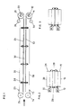
- the invention relates to a double belt molding machine for the production of foam plastic sheets as a continuous strand.
- the machine has two endless conveyor belts rotating in opposite directions. These can be belts or steel belts, for example, which are guided over a drive roller, slideways serving as support elements and around a deflection roller.
- the conveyor belts can also be plate belts which are guided over drive and deflection sprockets and are provided with support rollers which can run along support elements in the form of running rails.
- the two opposite, parallel and in the same direction running sections of the two bands limit the space used to form the continuous foam plastic strand on its two flat sides.
- the two narrow sides of this room can be delimited by side belts which also run around or by fixed side rails, the position of which is adjustable.
- slip can occur when the torque is transmitted from the drive drums to belts or steel belts by friction.
- different deviations in the diameter of the drive drums as a result of contamination or wear are possible.
- Contamination of the support plates of the conveyor belts can also influence the tensile forces.
- the weight of the band sections delimiting the top and bottom of the molding channel and the weight of the materials introduced into the channel, in particular the foam material and its laminations and supports stress the bottom band section and its support plate, which results in an increase in the tensile force in the bottom band while on the other hand the force of the mixture foaming in the molding channel loads both the lower and the upper band section. All the causes disturbing the equality of the tensile forces in the active belt sections require immediate compensation.
- the invention solves the problem of creating a double-belt molding machine of the type mentioned in the introduction, in which the creation of harmful shear forces within the foam strand in the molding channel is avoided with the simplest possible means.
- the lower endless conveyor belt is designated 10 and the upper one with 20.
- Each of these conveyor belts is guided by a drive roller 11 or 21.
- the drive rollers are each directly coupled to an electric individual drive motor 12, 22, from which they can be driven in the opposite direction of rotation, as indicated by the direction of the arrow.
- the directly opposite belt sections are via plate-shaped support elements 13, 23, which form slideways, and via deflection rollers 14, 24 and rollers 15, 16 and 25, 26 out.
- the deflection rollers or the rollers can also be designed as tension rollers for the belts 10, 20.
- the space 30 between the sections of the belts 10, 20 supported by the support elements 13, 23 serves to form the continuous foam plastic strand, which can be divided into the desired length after leaving the machine for producing foam plastic sheets.
- This channel-shaped space is delimited on its two flat sides by the active sections of the bands 10, 20.
- the two narrow sides of this shaped channel can be closed by (not shown) delimitations in the form of circumferential side bands or fixed adjustable side rails.
- the foamable plastic mixture is introduced into the molding channel 30 at one end of the machine, as indicated by an arrow on the left in FIG. 1, fills its cross-section during foaming and solidifies during its passage.
- adjusting devices 28 with a lifting spindle or the like can be spaced apart from one another. be arranged on both sides of the molding channel. These serve to evenly change the distance of the upper band 20 together with the associated support plates 23 and all other drive and guide devices belonging to it from the lower band 10, in order to thereby adjust the height of the molding channel 30 and thus the thickness of the foam plastic plates to be produced can.
- 2 and 3 which show the machine as seen in the direction of tape travel, are two different heights of the upper tape with those belonging to it Parts compared to the lower band and the parts belonging to it illustrated. In Fig. 2, the height of the molding channel 30 is greater than in Fig. 3.
- the drive rollers 11, 21 are provided with individual drive motors 12, 22, it is possible for the upper belt 20 with all its drive and guide parts as one together to form liftable unit 28 by means of the lifting devices, without the need for cumbersome adjustable transmissions between the drive rollers of the two belts and a drive motor common to them, and there are also no differences in the speed of the upper and lower belts when the tractive force changes.
- Regulation of the individual drive motors of the two belts for synchronism or for equal tensile forces in the two belts can be carried out with relatively simple means, for example when using AC or three-phase motors which can be regulated by frequency changes.
- the control for synchronism can take place depending on changes in the torque or the current consumption of the motors or instead depending on the running speed of the belt sections.
- the possibilities for forming a double belt forming machine according to the invention are not limited to the exemplary embodiment described above.
- direct current motors e.g. DC shunt motors, DC main shunt motors or DC double-circuit motors to use.
Landscapes
- Casting Or Compression Moulding Of Plastics Or The Like (AREA)
- Extrusion Moulding Of Plastics Or The Like (AREA)
- Macromonomer-Based Addition Polymer (AREA)
- Package Frames And Binding Bands (AREA)
- Braking Arrangements (AREA)
- Manufacturing Of Electric Cables (AREA)
- Moulds For Moulding Plastics Or The Like (AREA)
- Belt Conveyors (AREA)
- Saccharide Compounds (AREA)
- Acyclic And Carbocyclic Compounds In Medicinal Compositions (AREA)
- Pharmaceuticals Containing Other Organic And Inorganic Compounds (AREA)
- Magnetic Resonance Imaging Apparatus (AREA)
- Paper (AREA)
- Mechanical Treatment Of Semiconductor (AREA)
Abstract
Description
- Die Erfindung bezieht sich auf eine Doppelband-Formmaschine für die Herstellung von Schaumkunststoffplatten als fortlaufender Strang. Die Maschine weist zwei mit entgegengesetztem Drehsinn umlaufende endlose Transportbänder auf. Diese können beispielsweise Gurte oder Stahlbänder sein, welche über eine Antriebsrolle, als Stützelemente dienende Gleitbahnen und um eine Umlenkrolle geführt sind. Die Transportbänder können auch Plattenbänder sein, die über Antriebs- und Umlenkkettenräder geführt und mit Stützrollen versehen sind, die an Stützelementen in Form von Laufschienen entlanglaufen können. Die beiden sich gegenüberliegenden, parallel und in gleicher Richtung laufenden Abschnitte der beiden Bänder begrenzen den zur Formung des fortlaufenden Schaumkunststoffstranges dienenden Raum an seinen beiden Flachseiten. Die beiden Schmalseiten dieses Raumes können durch ebenfalls umlaufende Seitenbänder oder durch feststehende Seitenschienen begrenzt sein, deren Lage einstellbar ist.
- Zum Antrieb der Transportbänder war bei den bisher bekannten Ausführungsformen solcher Doppelband-Formmaschinen ein gemeinsamer, mit den Antriebsrollen bzw. Antriebskettenrädern gekuppelter elektrischer Antriebsmotor vorgesehen. Ein genauer Gleichlauf der aktiven, den Formungsraum begrenzenden Bandabschnitte war damit nicht oder nur mit erheblichem Aufwand an mechanischen Einrichtungen zu erreichen. Ein Gleichlauf der Bandabschnitte ist jedoch von großer Wichtigkeit, da das Entstehen von Scherkräften in dem Schaumstoffstrang, die dessen Gefügestruktur zerreißen könnten, vermieden werden muß. Die Erfüllung dieser Forderung ist schwierig, weil der Gleichlauf der aktiven Bandabschnitte und die Gleichheit der von den Bandabschnitten auf das Material des Schaumkunststoffstranges übertragenen Zugkräfte von den verschiedensten, nicht ohne weiteres zu beherrschenden Einflüßen abhängen. Z.B. kann bei der durch Friktion erfolgenden Übertragung des Drehmoments von den Antriebstrommeln auf Gurte oder Stahlbänder ein Schlupf auftreten. Ferner sind unterschiedliche Abweichungen des Durchmessers der Antriebstrommeln infolge Verschmutzung oder Abrieb möglich. Auch kann Verschmutzung der Stützplatten der Transportbänder eine Beeinflussung der Zugkräfte bewirken. Ferner belasten das Gewicht der den Formkanal oben und unten begrenzenden Bandabschnitte und das Gewicht der in den Kanal eingeführten Materialien, insbesondere das Schaumstoffmaterial sowie dessen Kaschierungen und Auflagen, den unteren Bandabschnitt und dessen Stützplatte, was eine Erhöhung der Zugkraft in dem unteren Band zur Folge hat, während andererseits die Kraft des in dem Formkanal aufschäumenden Gemischs sowohl den unteren als auch den oberen Bandabschnitt belastet. Alle die Gleichheit der Zugkräfte in den aktiven Bandabschnitten störenden Ursachen erfordern jeweils einen sofortigen Ausgleich.
- Es kommt hinzu, daß eine Höhenverstellbarkeit des oberen Bandes erforderlich ist, um Schaumkunststoffplatten verschiedener Dicke herstellen zu können. Mittels rein mechanischer verstellbarer Kupplungseinrichtungen zwischen dem Antriebsmotor und den Antriebsrollen bzw. Antriebskettenrädern der Bänder ist die Verwirklichung einer solchen Höhenverstellbarkeit äußerst schwierig.
- Die Erfindung löst die Aufgabe, eine Doppelband-Formmaschine der eingangs genannten Gattung zu schaffen, bei der mit möglichst einfachen Mitteln eine Entstehung schädlicher Scherkräfte innerhalb des Schaumstoffstranges im Formkanal vermieden ist.
- Zur Lösung dieser Aufgabe wird vorgeschlagen, daß bei Doppelband-Formmaschinen der eingangs genannten Art die Antriebsrollen- bzw. -kettenräder der beiden Bänder mit auf Gleichlauf der sich gegenüberliegenden Bandabschnitte geregelten elektrischen Einzelantrieben versehen sind.
- Bei einer solchen Doppelband-Formmaschine wird auf einfache Weise sowohl beim Anfahren als auch während des Betriebes ein genauer Gleichlauf der aktiven, den Formkanal und damit den Schaumkunststoffstrang begrenzenden Bandabschnitte sowie Gleichheit der von den Bandabschnitten auf den Schaumkunststoffstrang übertragenen Zugkräfte erreicht, so daß schädliche Scherkräfte in diesem nicht auftreten können. Umständliche und empfindliche mechanische Kraftübertragungselemente, wie sie zur Übertragung des Drehmoments von einem gemeinsamen Antriebsmotor aus auf die Antriebsrollen benötigt werden, sind nicht mehr erforderlich. Ein weiterer Vorteil der Erfindung besteht darin, daß die Voraussetzung für ein besonders einfaches Verändern des Abstandes der einander gegenüber angeordneten Bänder geschaffen ist, weil die das obere umlaufende Band tragenden Rollen oder Kettenräder zusammen mit dem Einzelantriebsmotor des oberen Bandes gemeinsam höhenverstellbar angeordnet werden können.
- Vorteilhafte Ausgestaltungen der Erfindung sind in den Unteransprüchen gekennzeichnet.
- Im folgenden wird der Gegenstand der Erfindung in den Zeichnungen erläutert. Es zeigt
- Fig. 1 schematisch die Seitenansicht der wesentlichen Teile einer Doppelband-Formmaschine gemäß der Erfindung,
- Fig. 2, in Bandlaufrichtung gesehen, die höhenverstellbare Anordnung der Bänder bei verhältnismäßig großem Abstand und
- Fig. 3 dieselbe Anordnung bei verhältnismäßig kleinem Abstand der Bänder.
- In Fig. 1 ist das untere endlose Transportband mit 10 und das obere mit 20 bezeichnet. Jedes dieser Transportbänder ist über eine Antriebsrolle 11 bzw. 21 geführt. Die Antriebsrollen sind mit je einem elektrischen Einzelantriebsmotor 12, 22 direkt gekuppelt, von dem sie mit entgegengesetztem Drehsinn, wie durch Pfeilrichtung angedeutet, angetrieben werden können.Die einander unmittelbar gegenüberliegenden Bandabschnitte sind über plattenförmige Stützelemente 13, 23, welche Gleitbahnen bilden, sowie über Umlenkrollen 14, 24 und Laufrollen 15, 16 bzw. 25, 26 geführt. Die Umlenkrollen oder die Laufrollen können auch als Spannrollen für die Bänder 10, 20 ausgebildet sein.
- Der Raum 30 zwischen den von den Stützelementen 13, 23 abgestützten Abschnitten der Bänder 10, 20 dient zur Formung des fortlaufenden Schaumkunststoffstranges, der nach dem Verlassen der Maschine zur Herstellung von Schaumkunststoffplatten von der gewünschten Länge unterteilt werden kann. Dieser kanalförmige Raum wird an seinen beiden Flachseiten von den aktiven Abschnitten der Bänder 10, 20 begrenzt. Die beiden Schmalseiten dieses Formkanals können durch (nicht dargestellte) Begrenzungen in Form ebenfalls umlaufender Seitenbänder oder feststehender einstellbarer Seitenschienen geschlossen sein. Das aufschäumbare Kunststoffgemisch wird am einen Ende der Maschine, wie in Fig. 1 links mit einem Pfeil angedeutet, in den Formkanal 30 eingeführt, füllt dessen Querschnitt beim Aufschäumen aus und verfestigt sich während seines Durchlaufs.
- Längs der Maschine können in Abständen voneinander Verstellvorrichtungen 28 mit Hubspindel od.dgl. zu beiden Seiten des Formkanals angeordnet sein. Diese dienen dazu, den Abstand des oberen Bandes 20 nebst der dazugehörigen Stützplatten 23 und aller anderen zu ihm gehörenden Antriebs- und Führungseinrichtungen von dem unteren Band 10 gleichmäßig zu verändern, um dadurch die Höhe des Formkanals 30 und damit die Dicke der herzustellenden Schaumkunststoffplatten einstellen zu können. In Fig. 2 und 3, welche die Maschine in Bandlaufrichtung gesehen darstellen, sind zwei verschiedene Höhenlagen des oberen Bandes mit den zu ihm gehörenden Teilen gegenüber dem unteren Band und den zu diesem gehörenden Teilen veranschaulicht. Bei Fig. 2 ist die Höhe des Formkanals 30 größer als bei Fig. 3. Dadurch, daß die Antriebsrollen 11, 21 mit Einzelantriebsmotoren 12, 22 versehen sind, wird es möglich, das obere Band 20 mit allen seinen Antriebs- und Führungsteilen als eine gemeinsam mittels der Hubvorrichtungen 28 anhebbare Einheit auszubilden, ohne daß umständliche verstellbare Transmissionen zwischen den Antriebsrollen der beiden Bänder und einem für diese gemeinsamen Antriebsmotor erforderlich wären, und es ergeben sich auch keine Ungleichheiten der Geschwindigkeit des oberen und des unteren Bandes bei Änderung der Zugkraft. Eine Regelung der Einzelantriebsmotoren beider Bänder auf Gleichlauf bzw. auf Gleichheit der Zugkräfte in den beiden Bändern ist mit verhältnismäßig einfachen Mitteln durchführbar, beispielsweise bei Verwendung durch Frequenzänderungen regelbarer Wechselstrom- oder Drehstrommotoren. Die Regelung auf Gleichlauf kann in Abhängigkeit von Änderungen des Drehmoments oder der Stromaufnahme der Motoren oder stattdessen in Abhängigkeit von der Laufgeschwindigkeit der Bandabschnitte erfolgen.
- Die Möglichkeiten zur Ausbildung einer Doppelband-Formmaschine gemäß der Erfindung sind jedoch nicht auf das vorstehend beschriebene Ausführungsbeispiel beschränkt. So ist es insbesondere auch möglich, als elektrische Einzelantriebe Gleichstrommotoren, wie z.B. Gleichstromnebenschlußmotoren, Gleichstromhauptschlußmotoren oder Gleichstromdoppelschlußmotoren zu verwenden.
Claims (9)
Priority Applications (10)
| Application Number | Priority Date | Filing Date | Title |
|---|---|---|---|
| EP85108944A EP0209609B1 (de) | 1985-07-17 | 1985-07-17 | Doppelband-Formmaschine |
| DE8585108944T DE3570620D1 (en) | 1985-07-17 | 1985-07-17 | Double endless belt-shaping apparatus |
| AT85108944T ATE43533T1 (de) | 1985-07-17 | 1985-07-17 | Doppelband-formmaschine. |
| FI862914A FI862914A7 (fi) | 1985-07-17 | 1986-07-11 | Kaksoisnauha-muovauskone. |
| DD86292519A DD259171A5 (de) | 1985-07-17 | 1986-07-15 | Doppelband-formmaschine |
| CS865401A CS261897B2 (en) | 1985-07-17 | 1986-07-16 | Two-band moulding machine |
| NO862872A NO862872L (no) | 1985-07-17 | 1986-07-16 | Dobbeltbaand-foremaskin. |
| HU862939A HUT42991A (en) | 1985-07-17 | 1986-07-16 | Double-belt molding machine |
| CN86104919.5A CN1005396B (zh) | 1985-07-17 | 1986-07-17 | 双带成型机 |
| US07/455,841 US4981427A (en) | 1985-07-17 | 1989-12-21 | Double belt moulding machine |
Applications Claiming Priority (1)
| Application Number | Priority Date | Filing Date | Title |
|---|---|---|---|
| EP85108944A EP0209609B1 (de) | 1985-07-17 | 1985-07-17 | Doppelband-Formmaschine |
Publications (2)
| Publication Number | Publication Date |
|---|---|
| EP0209609A1 true EP0209609A1 (de) | 1987-01-28 |
| EP0209609B1 EP0209609B1 (de) | 1989-05-31 |
Family
ID=8193625
Family Applications (1)
| Application Number | Title | Priority Date | Filing Date |
|---|---|---|---|
| EP85108944A Expired EP0209609B1 (de) | 1985-07-17 | 1985-07-17 | Doppelband-Formmaschine |
Country Status (10)
| Country | Link |
|---|---|
| US (1) | US4981427A (de) |
| EP (1) | EP0209609B1 (de) |
| CN (1) | CN1005396B (de) |
| AT (1) | ATE43533T1 (de) |
| CS (1) | CS261897B2 (de) |
| DD (1) | DD259171A5 (de) |
| DE (1) | DE3570620D1 (de) |
| FI (1) | FI862914A7 (de) |
| HU (1) | HUT42991A (de) |
| NO (1) | NO862872L (de) |
Cited By (2)
| Publication number | Priority date | Publication date | Assignee | Title |
|---|---|---|---|---|
| FR2704477A1 (fr) * | 1993-04-26 | 1994-11-04 | Hainaut Sa Fibres | Procédé de fabrication de plaques planes ondulées ou nervurées à base de résine thermodurcissable et dispositif pour la mise en Óoeuvre de ce procédé. |
| EP0686470A3 (de) * | 1994-06-06 | 1996-04-10 | Nippon Catalytic Chem Ind | Verfahren zur kontinuierlichen Herstellung eines Kunststeines |
Families Citing this family (15)
| Publication number | Priority date | Publication date | Assignee | Title |
|---|---|---|---|---|
| AT395927B (de) * | 1991-05-31 | 1993-04-26 | Koenig Helmut | Vorrichtung zur formung portionierter teigstuecke |
| FI122417B (sv) | 2002-06-05 | 2012-01-13 | Selvaag Spinoff As | Förfarande för framställning av skivlika fiberarmerade produkter |
| US8752348B2 (en) * | 2005-02-25 | 2014-06-17 | Syntheon Inc. | Composite pre-formed construction articles |
| BRPI0607914A2 (pt) * | 2005-02-25 | 2010-03-23 | Nova Chem Inc | painel de edificaÇço compàsito, mÉtodo para construir uma edificaÇço, edificaÇço, mÉtodo para fazer negàcio entre um fabricante de painel de edificaÇço compàsito e um cliente, e, caibro de armaÇço |
| MX2007009959A (es) * | 2005-02-25 | 2007-09-26 | Nova Chem Inc | Composiciones de peso ligero y articulos que contienen las mismas. |
| MX2007011640A (es) | 2005-03-22 | 2008-01-18 | Nova Chem Inc | Composiciones de concreto de peso ligero. |
| US7677009B2 (en) * | 2007-02-02 | 2010-03-16 | Nova Chemicals Inc. | Roof truss system |
| US8048219B2 (en) | 2007-09-20 | 2011-11-01 | Nova Chemicals Inc. | Method of placing concrete |
| US9028238B2 (en) | 2012-02-16 | 2015-05-12 | Sealed Air Corporation (Us) | Molding apparatus and method |
| US9033694B2 (en) | 2012-02-16 | 2015-05-19 | Sealed Air Corporation (Us) | Molding apparatus and method |
| CN103009624A (zh) * | 2012-12-25 | 2013-04-03 | 如冈自动化控制技术(上海)有限公司 | 一种双驱动履带式热缩管加热机 |
| CN104416692A (zh) * | 2013-08-22 | 2015-03-18 | 赵武敏 | 带轮推进式送料机械装置 |
| CN103921434A (zh) * | 2014-04-11 | 2014-07-16 | 如冈自动化控制技术(上海)有限公司 | 一种吞吐式热缩管加热机 |
| WO2016076895A1 (en) * | 2014-11-16 | 2016-05-19 | Uni-Pixel Displays, Inc. | Dual web conveyance |
| CN113936864B (zh) * | 2021-08-12 | 2025-04-25 | 诸暨中澳自动化设备有限公司 | 用于对线束端部进行热缩的履带式设备及其方法 |
Citations (7)
| Publication number | Priority date | Publication date | Assignee | Title |
|---|---|---|---|---|
| GB1048268A (en) * | 1963-09-12 | 1966-11-16 | Marley Tile Co Ltd | Polyurethane foam materials and apparatus for the production thereof |
| US3887314A (en) * | 1972-06-29 | 1975-06-03 | Siempelkamp Gmbh & Co | System for the production of pressed board |
| FR2254431A1 (de) * | 1973-12-17 | 1975-07-11 | Zelon Ind Ltd | |
| US4178144A (en) * | 1977-09-22 | 1979-12-11 | Kornylak Corporation | Molding conveyor drive |
| GB2053824A (en) * | 1979-07-19 | 1981-02-11 | Hunting Electrocontrols Ltd | Endless conveyors |
| US4265608A (en) * | 1980-06-30 | 1981-05-05 | Tunador Engineering, Inc. | Endless belt molding apparatus |
| DE3018357C2 (de) * | 1980-05-14 | 1984-09-27 | Hoesch Werke Ag, 4600 Dortmund | Antrieb eines Doppelplattenbandes zur kontinuierlichen Herstellung ausgeschäumter Verbundelemente |
Family Cites Families (9)
| Publication number | Priority date | Publication date | Assignee | Title |
|---|---|---|---|---|
| US3381609A (en) * | 1966-06-20 | 1968-05-07 | Neil Malarkey Jr. | Filter press |
| DE2018629A1 (en) * | 1970-04-18 | 1971-12-30 | Zippel & Co Kg R | Foamed plastic wall prodn - using endless plastic belt backed by adjustable moulding jaws |
| US3957413A (en) * | 1974-01-25 | 1976-05-18 | Lieberman Abraham B | Apparatus for producing high-speed production of a pressure generating product |
| DE2725640B2 (de) * | 1977-06-07 | 1979-04-05 | Kuesters, Eduard, 4150 Krefeld | Steuersystem für eine kontinuierlich arbeitende Presse |
| DE2922152A1 (de) * | 1979-05-31 | 1980-12-18 | Sandvik Conveyor Gmbh | Verfahren und vorrichtung zur herstellung von folien und platten aus sinterfaehigen pulvern |
| CH661160A5 (de) * | 1979-08-17 | 1987-06-30 | Sig Schweiz Industrieges | Verfahren zum betrieb eines fremderregten oder nebenschlussgeschalteten gleichstrommotors, anordnung zur ausfuehrung des verfahrens sowie anwendung des verfahrens. |
| JPS57110421A (en) * | 1980-12-29 | 1982-07-09 | Sakushin Kogyo Kk | Apparatus for molding long synthetic resin plate or sheet |
| DE3234082C2 (de) * | 1982-09-14 | 1987-01-29 | Held, Kurt, 7218 Trossingen | Doppelbandpresse |
| DE3313542C1 (de) * | 1983-04-14 | 1984-08-30 | Fried. Krupp Gmbh, 4300 Essen | Antriebsvorrichtung fuer Giesswalzen |
-
1985
- 1985-07-17 EP EP85108944A patent/EP0209609B1/de not_active Expired
- 1985-07-17 DE DE8585108944T patent/DE3570620D1/de not_active Expired
- 1985-07-17 AT AT85108944T patent/ATE43533T1/de not_active IP Right Cessation
-
1986
- 1986-07-11 FI FI862914A patent/FI862914A7/fi not_active Application Discontinuation
- 1986-07-15 DD DD86292519A patent/DD259171A5/de not_active IP Right Cessation
- 1986-07-16 CS CS865401A patent/CS261897B2/cs unknown
- 1986-07-16 HU HU862939A patent/HUT42991A/hu unknown
- 1986-07-16 NO NO862872A patent/NO862872L/no unknown
- 1986-07-17 CN CN86104919.5A patent/CN1005396B/zh not_active Expired
-
1989
- 1989-12-21 US US07/455,841 patent/US4981427A/en not_active Expired - Fee Related
Patent Citations (7)
| Publication number | Priority date | Publication date | Assignee | Title |
|---|---|---|---|---|
| GB1048268A (en) * | 1963-09-12 | 1966-11-16 | Marley Tile Co Ltd | Polyurethane foam materials and apparatus for the production thereof |
| US3887314A (en) * | 1972-06-29 | 1975-06-03 | Siempelkamp Gmbh & Co | System for the production of pressed board |
| FR2254431A1 (de) * | 1973-12-17 | 1975-07-11 | Zelon Ind Ltd | |
| US4178144A (en) * | 1977-09-22 | 1979-12-11 | Kornylak Corporation | Molding conveyor drive |
| GB2053824A (en) * | 1979-07-19 | 1981-02-11 | Hunting Electrocontrols Ltd | Endless conveyors |
| DE3018357C2 (de) * | 1980-05-14 | 1984-09-27 | Hoesch Werke Ag, 4600 Dortmund | Antrieb eines Doppelplattenbandes zur kontinuierlichen Herstellung ausgeschäumter Verbundelemente |
| US4265608A (en) * | 1980-06-30 | 1981-05-05 | Tunador Engineering, Inc. | Endless belt molding apparatus |
Cited By (3)
| Publication number | Priority date | Publication date | Assignee | Title |
|---|---|---|---|---|
| FR2704477A1 (fr) * | 1993-04-26 | 1994-11-04 | Hainaut Sa Fibres | Procédé de fabrication de plaques planes ondulées ou nervurées à base de résine thermodurcissable et dispositif pour la mise en Óoeuvre de ce procédé. |
| EP0686470A3 (de) * | 1994-06-06 | 1996-04-10 | Nippon Catalytic Chem Ind | Verfahren zur kontinuierlichen Herstellung eines Kunststeines |
| US5658508A (en) * | 1994-06-06 | 1997-08-19 | Nippon Shokubai Co., Ltd. | Method for continuously forming a synthetic stone |
Also Published As
| Publication number | Publication date |
|---|---|
| DE3570620D1 (en) | 1989-07-06 |
| FI862914L (fi) | 1987-01-18 |
| HUT42991A (en) | 1987-09-28 |
| CS540186A2 (en) | 1988-06-15 |
| FI862914A7 (fi) | 1987-01-18 |
| EP0209609B1 (de) | 1989-05-31 |
| NO862872L (no) | 1987-01-19 |
| NO862872D0 (no) | 1986-07-16 |
| CS261897B2 (en) | 1989-02-10 |
| CN1005396B (zh) | 1989-10-11 |
| FI862914A0 (fi) | 1986-07-11 |
| US4981427A (en) | 1991-01-01 |
| CN86104919A (zh) | 1987-04-01 |
| ATE43533T1 (de) | 1989-06-15 |
| DD259171A5 (de) | 1988-08-17 |
Similar Documents
| Publication | Publication Date | Title |
|---|---|---|
| EP0209609B1 (de) | Doppelband-Formmaschine | |
| DE2740807A1 (de) | Bandfoerderer | |
| DE3336013C2 (de) | Doppeltransportband zum kontinuierlichen Herstellen von mit Deckschichten kaschierten, in situ geschäumten Schaumstoffbahnen aus einem fließfähigen Reaktionsgemisch | |
| EP0620337B1 (de) | Anlage zum Befahren von Gebäudewänden | |
| DE2210829B2 (de) | Maschine zur oberflaechenbehandlung von plattenfoermigen betonelementen | |
| DE2146554C3 (de) | Verfahren und Vorrichtung zum LangroUen und/oder Langwirken von Teigstucken Fr. Winkler KG, Spezialfabrik für Bäckereimaschinen und Backöfen, 7730 Villingen | |
| DE69002108T2 (de) | Vorrichtung zum Bearbeiten plattenförmiger Werkstoffe. | |
| DE172051T1 (de) | Verfahren, einrichtung und apparat zur herstellung von gebaeck. | |
| DE1574639A1 (de) | Vorrichtung zum Einstellen der Lage eines in seiner Laengsrichtung bewegten Materialstreifens in bezug auf eine Bezugsebene | |
| DE2635010A1 (de) | Trockenpresse mit endlosen, seitlich abnehmbaren baendern | |
| DE2729263A1 (de) | Vorrichtung zum kontinuierlichen pressen von pressgutmatten im zuge der herstellung von spanplatten, faserplatten u.dgl. | |
| DE3207384A1 (de) | Vorrichtung zur folienreckung | |
| DE909258C (de) | Antriebsvorrichtung, insbesondere fuer den Plattenteller einer Sprechmaschine | |
| EP0209608A1 (de) | Doppelband-Formmaschine für die Herstellung von Schaumkunststoffplatten als fortlaufender Strang | |
| DE2220553A1 (de) | Kontinuierlich arbeitende presse zum herstellen von platten, wie span-, faserplatten od.dgl | |
| DE1704739C3 (de) | Einrichtung zur aufeinanderfolgenden Zuführung von Außenschichtplatten zu einer Ausschäumvorrichtung | |
| DE2736099C2 (de) | Kontinuierlich arbeitende Presse | |
| EP3548202B1 (de) | Raupengiessmaschine zum herstellen eines giessguts aus flüssigem metall | |
| DE1579102C (de) | Einrichtung zum Herstellen eines For dergurtes | |
| DE3616415A1 (de) | Vorrichtung zur handhabung von floatglaskopfwalzen | |
| DE3008521A1 (de) | Fraesmaschine zum einfraesen von ausnehmungen in profilstuecke fuer tuer- oder fensterrahmen | |
| DE2447504C3 (de) | Vorrichtung zur Halterung und Führung eines Stranges in wenigstens einem Teil einer Sekundärkühlzone einer Strang- | |
| DE2534933C3 (de) | Endlos-Plattenbänder an einer kontinuierlich arbeitenden, zur Herstellung von Preßplatten, wie Span-, Faser-Platten o.dgl., geeigneten Vor- oder Fertigpresse | |
| DE2254972A1 (de) | Flaschenreinigungsmaschine | |
| DE2403209C3 (de) | Kontinuierlich arbeitende Presse zum Herstellen von Platten, wie Span-, Faserplatten o.dgl |
Legal Events
| Date | Code | Title | Description |
|---|---|---|---|
| PUAI | Public reference made under article 153(3) epc to a published international application that has entered the european phase |
Free format text: ORIGINAL CODE: 0009012 |
|
| 17P | Request for examination filed |
Effective date: 19861106 |
|
| AK | Designated contracting states |
Kind code of ref document: A1 Designated state(s): AT BE CH DE FR GB IT LI LU NL SE |
|
| 17Q | First examination report despatched |
Effective date: 19870710 |
|
| ITF | It: translation for a ep patent filed | ||
| GRAA | (expected) grant |
Free format text: ORIGINAL CODE: 0009210 |
|
| AK | Designated contracting states |
Kind code of ref document: B1 Designated state(s): AT BE CH DE FR GB IT LI LU NL SE |
|
| REF | Corresponds to: |
Ref document number: 43533 Country of ref document: AT Date of ref document: 19890615 Kind code of ref document: T |
|
| GBT | Gb: translation of ep patent filed (gb section 77(6)(a)/1977) | ||
| REF | Corresponds to: |
Ref document number: 3570620 Country of ref document: DE Date of ref document: 19890706 |
|
| ET | Fr: translation filed | ||
| PLBI | Opposition filed |
Free format text: ORIGINAL CODE: 0009260 |
|
| PLBI | Opposition filed |
Free format text: ORIGINAL CODE: 0009260 |
|
| 26 | Opposition filed |
Opponent name: MASCHINENFABRIK HENNECKE GMBH, Effective date: 19900216 |
|
| 26 | Opposition filed |
Opponent name: ELASTOGRAN POLYURETHANE GMBH Effective date: 19900222 Opponent name: MASCHINENFABRIK HENNECKE GMBH, Effective date: 19900216 |
|
| NLR1 | Nl: opposition has been filed with the epo |
Opponent name: MASCHINENFABRIK HENNECKE GMBH |
|
| NLR1 | Nl: opposition has been filed with the epo |
Opponent name: ELASTOGRAN POLYURETHANE GMBH. |
|
| PGFP | Annual fee paid to national office [announced via postgrant information from national office to epo] |
Ref country code: SE Payment date: 19910718 Year of fee payment: 7 Ref country code: GB Payment date: 19910718 Year of fee payment: 7 |
|
| PGFP | Annual fee paid to national office [announced via postgrant information from national office to epo] |
Ref country code: LU Payment date: 19910724 Year of fee payment: 7 |
|
| ITTA | It: last paid annual fee | ||
| PGFP | Annual fee paid to national office [announced via postgrant information from national office to epo] |
Ref country code: NL Payment date: 19910731 Year of fee payment: 7 Ref country code: FR Payment date: 19910731 Year of fee payment: 7 Ref country code: CH Payment date: 19910731 Year of fee payment: 7 Ref country code: BE Payment date: 19910731 Year of fee payment: 7 Ref country code: AT Payment date: 19910731 Year of fee payment: 7 |
|
| PGFP | Annual fee paid to national office [announced via postgrant information from national office to epo] |
Ref country code: DE Payment date: 19910927 Year of fee payment: 7 |
|
| EPTA | Lu: last paid annual fee | ||
| PLBM | Termination of opposition procedure: date of legal effect published |
Free format text: ORIGINAL CODE: 0009276 |
|
| STAA | Information on the status of an ep patent application or granted ep patent |
Free format text: STATUS: OPPOSITION PROCEDURE CLOSED |
|
| 27C | Opposition proceedings terminated |
Effective date: 19920228 |
|
| PG25 | Lapsed in a contracting state [announced via postgrant information from national office to epo] |
Ref country code: LU Free format text: LAPSE BECAUSE OF NON-PAYMENT OF DUE FEES Effective date: 19920717 Ref country code: GB Effective date: 19920717 Ref country code: AT Effective date: 19920717 |
|
| PG25 | Lapsed in a contracting state [announced via postgrant information from national office to epo] |
Ref country code: SE Effective date: 19920718 |
|
| PG25 | Lapsed in a contracting state [announced via postgrant information from national office to epo] |
Ref country code: LI Effective date: 19920731 Ref country code: CH Effective date: 19920731 Ref country code: BE Effective date: 19920731 |
|
| BERE | Be: lapsed |
Owner name: PRIGNITZ HERBERT Effective date: 19920731 |
|
| PG25 | Lapsed in a contracting state [announced via postgrant information from national office to epo] |
Ref country code: NL Effective date: 19930201 |
|
| NLV4 | Nl: lapsed or anulled due to non-payment of the annual fee | ||
| GBPC | Gb: european patent ceased through non-payment of renewal fee |
Effective date: 19920717 |
|
| PG25 | Lapsed in a contracting state [announced via postgrant information from national office to epo] |
Ref country code: FR Effective date: 19930331 |
|
| REG | Reference to a national code |
Ref country code: CH Ref legal event code: PL |
|
| PG25 | Lapsed in a contracting state [announced via postgrant information from national office to epo] |
Ref country code: DE Effective date: 19930401 |
|
| REG | Reference to a national code |
Ref country code: FR Ref legal event code: ST |
|
| EUG | Se: european patent has lapsed |
Ref document number: 85108944.1 Effective date: 19930204 |