EP0209839A2 - Vorrichtung und Verfahren zur Dekodierung einer Folge pseudoternärer digitaler Signale - Google Patents
Vorrichtung und Verfahren zur Dekodierung einer Folge pseudoternärer digitaler Signale Download PDFInfo
- Publication number
- EP0209839A2 EP0209839A2 EP86109713A EP86109713A EP0209839A2 EP 0209839 A2 EP0209839 A2 EP 0209839A2 EP 86109713 A EP86109713 A EP 86109713A EP 86109713 A EP86109713 A EP 86109713A EP 0209839 A2 EP0209839 A2 EP 0209839A2
- Authority
- EP
- European Patent Office
- Prior art keywords
- estimator
- sample
- amplitude
- sample signal
- signal
- Prior art date
- Legal status (The legal status is an assumption and is not a legal conclusion. Google has not performed a legal analysis and makes no representation as to the accuracy of the status listed.)
- Withdrawn
Links
Images

Classifications
-
- H—ELECTRICITY
- H03—ELECTRONIC CIRCUITRY
- H03M—CODING; DECODING; CODE CONVERSION IN GENERAL
- H03M5/00—Conversion of the form of the representation of individual digits
- H03M5/02—Conversion to or from representation by pulses
- H03M5/16—Conversion to or from representation by pulses the pulses having three levels
- H03M5/18—Conversion to or from representation by pulses the pulses having three levels two levels being symmetrical with respect to the third level, i.e. balanced bipolar ternary code
-
- H—ELECTRICITY
- H03—ELECTRONIC CIRCUITRY
- H03M—CODING; DECODING; CODE CONVERSION IN GENERAL
- H03M13/00—Coding, decoding or code conversion, for error detection or error correction; Coding theory basic assumptions; Coding bounds; Error probability evaluation methods; Channel models; Simulation or testing of codes
- H03M13/03—Error detection or forward error correction by redundancy in data representation, i.e. code words containing more digits than the source words
- H03M13/23—Error detection or forward error correction by redundancy in data representation, i.e. code words containing more digits than the source words using convolutional codes, e.g. unit memory codes
Definitions
- the present invention relates to an apparatus and a method for decoding a sequence of psuedo-ternary digital signals.
- Pseudo-ternary digital signals are defined as signals having three possible nominal values which are constrained from signal to signal in a particular way.
- a detection or decoding process is fundamental to the operation of communication or recording channels.
- a signal is received or read back which consists of a nominal signal which is dependent on the data sent or written and contamination due to noise and/or component imperfections.
- the detection or decoding process is the process of decoding the received or readback signal in order to be able to estimate and interpret the sent or written data.
- binary data is typically encoded in an NRZI code.
- a "1” is encoded by reversing the polarity of the write current, while a “0” is encoded by not reversing the polarity of the write current.
- a "1” is represented by a transition between the two magnetic states of the medium while a "0” is represented by maintaining the same state.
- the transitions between states can occur only at certain equally spaced positions or time instants, corresponding to certain equally-spaced clock times for constant velocity of the recording medium in the writing and reading process.
- Each bit of data is therefore represented by a positive pulse, a negative pulse or by no pulse, each spaced at periodic intervals.
- the readback signal is not ideal, however, being contaminated by noise and component imperfections. Some method is needed for the interpretation of the non-ideal signal as binary data. A straightforward method is to detect the signal by comparison with positive and negative thresholds. A "1" is detected when the signal is greater than the positive threshold or less than the negative threshold, a "0" otherwise.
- the readback signal from the magnetic recording channel can include a positive pulse and a negative pulse which may or may not be separated by a zero value pulse at associated clock times. Since the pulses of one polarity represent transitions between positive and negative saturation of the medium and pulses of the other polarity represent transitions between negative and positive saturation, there cannot be two pulses of the same polarity without an intervening pulse of the opposite polarity. Thus, the polarities of the pulses representing a "1" must alternate. This alternating polarity rule which constrains the polarity of successive "1" pulses, is referred to as the pseudo-ternary constraint and a sequence of digital signals conforming to this constraint is defined as a sequence of pseudo-ternary digital signals.
- the simple threshold detection discussed earlier would result in a maximum likelihood of detection if the signal were actually ternary.
- the pseudo-ternary constraint implies that detection in context can be used to achieve maximum likelihood of detection, which results in a lower probability of error than that which would result from simple threshold detection.
- the Viterbi algorithm is a solution to the problem of, given a sequence z of observations of a discrete time finite state Markov process in memory-less noise, finding state sequence x for which the a posteriori probability p[x/z] is a maximum. This means that decoding is "decoding in context" in order to recover the symbols.
- a Viterbi detector generates all possible symbols for a given coding that is applied to it. This detector thus reduces the number of sequences about which a detection decision must be made to a few survivor sequences.
- the survivor sequences are detected by means of a metric which is a measure of the likelihood that a given survivor sequence is the actual sequence.
- a metric in detecting a survivor is an unbounded number sequence if each survivor is measured absolutely.
- the Viterbi algorithm thus essentially provides a systematic methodology for serializing the parallel detection implied by basic maximum likelihood.
- the methodology entails, at any point, a number of survivor sequences. There is one and only one of the survivor sequences for each possible sequence of future events.
- the survivor sequence is the most probable past sequence consistent with the future sequence. Since any past sequence is consistent with a number of future sequences, many future sequences share the same survivor sequence.
- the Viterbi method permits computing the survivor sequences and corresponding metrics from the sample and metric value at the time of the n + 1 sample.
- these metrics may increase without bounds.
- EP-A-133480 This specification shows a detection process based on calculations which involve only the difference between metrics.
- threshold detection levels are adjusted to increase noise immunity while converting a three-level code into a two-level code.
- the object of the present invention is to provide an improved apparatus and a method for decoding a sequence of psuedo-ternary digital signals.
- the present invention relates to apparatus for decoding a sequence of pseudo-ternary digital signals, wherein each signal can have one of three possible values, a zero value, a positive value or a negative value.
- the apparatus is of the type which comprises storage means for storing an estimator representing each of the possible positive and negative values, sampling means for sampling the sequence of signals at predetermined time intervals and obtaining sample signals, and comparison means for comparing each sample signal with the estimator to determine whether each sample signal is equivalent to one of the possible values.
- Apparatus in accordance with the invention is characterised in that the comparison means comprises estimator changing means for changing the current amplitude of the estimator to the amplitude of the sample signal when the amplitude of the sample signal appears to represent one of the possible positive or negative values more accurately than the current amplitude of the estimator.
- the invention also relates to a method of decoding a sequence of pseudo-ternary digital signals, wherein each signal can have one of three possible values, a zero value, a positive value or a negative value, utilising apparatus as defined above.
- the apparatus of the invention is used to implement a process for resolving ambiguous signals in a pseudo-ternary encoded sequence of signals using maximum likelihood detection as a form of context decoding.
- Both positive and negative pulses are present in the sequence of signals.
- the signal sequence is sampled at the clock times when pulses representing data could occur.
- the critical step is the recursive comparison between sample signals and the estimator and replacement of the estimator with a sample in certain circumstances. The replacement takes place if the amplitude of the sample signal exceeds the amplitude of the estimator by more than a specified amount. Otherwise the estimator is confirmed as currently representing one of the possible positive and negative values of the signal. Detection of a positive transistion of one polarity changes the mode of the process into searching for an opposite polarity transition.
- the detection and decoding process comprises searching for a positive sample signal or searching for a negative sample signal, either of which represent a "1".
- searching for a positive "1” the most positive sample signal is stored as the most likely "1” and is confirmed as a "1” by observation of the next sample signal which is less than it by more than a nominal amplitude.
- search for a negative “1” begins, and the most negative sample signal is stored as the next most likely "1". This stored value is confirmed by observation of the next sample signal which is greater than this most likely "1” by more than a nominal amplitude.
- the search for a positive "1” begins again when a negative "1" has been detected.
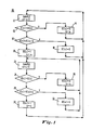
- Fig. 1 illustrates a maximum likelihood detection or decoding process 10 which may be used to minimise the probability of error in transmitting data in a communication or recording device channel.
- the maximum likelihood detection process 10 is always in one of two modes of searching samples.
- mode one the signal in the communication or recording device channel, represented by the symbol a n , is searched for a positive sample; in mode two, the signal is searched for a negative sample.
- mode two the signal is searched for a negative sample.
- mode one the most positive sample of the signal is used as an estimator of a positive "1" and is recorded as the most likely "1". The estimator is then compared with samples which follow it and is confirmed as a "1" by observation of a sample which is less than it by more than the magnitude of a nominal amplitude.
- the nominal amplitude has approximately the magnitude which a positive "1” or a negative “1" should have under ideal channel conditions. In actual practice it is determined by adjusting the gain control of the channel by automatic gain control techniques well known in the art. Thus, a sample must be less than the estimator by a sufficient amount to permit the conclusion that the estimator is a positive "1".
- n represents the time index of present sample, where the present sample is defined to be the sample which is currently being decoded.
- the index of the sample which is currently the most likely "1” is indicated as k, where the most likely "1" is defined as the most positive sample of the output channel of the recording device channel which has been processed by process 10 during the current search for a positive "1".
- the magnitude of a nominal "1" sample is denoted as A.
- samples decoded by process 10 may have either a negative or a positive amplitude depending on whether the signal received from the readback channel has a voltage level which is above or below the "0" level. All samples have a positive magnitude which is defined as the absolute value of the amplitude.
- Samples of the signal which is to be decoded are produced in a conventional manner and provided to process 10 by an analog-to-digital converter (not shown).
- an analog-to-digital converter (not shown).
- block 12 of Fig. 1 as new sample n+1 replaces sample n, it becomes the current sample.
- the operator X[i] shown in diamond 13 determines the amplitude of the ith sample. Thus, in diamond 13 a determination is made whether the amplitude of the nth sample, X[n], is larger than the amplitude of the most likely "1", X[k], in which k is the index of the most likely "1" as previously sampled. If the amplitude of current sample, n, is larger than previous sample k, the bit with time index k is assigned a value of "0". The sample n, which now appears to be the most likely "1”, is selected to replace the previous sample k and is thereby designated as the new most likely "1".
- Fig. 2 shows a graph in which the amplitude of samples S on axis 38 are compared with estimators E on axis 48. Each sample will fall into one of three regions 42, 44, 46 depending on the result of the associated comparison.
- Dotted line 34 and axis 38 form the boundary of region 42 in which is located each sample S which is larger than the estimator E as indicated in block 40.
- the estimator E the index of the estimator is revised and the estimator is replaced as described above referring to block 14.
- dotted lines 34, 36 define region 44 in which the estimator E is greater than the sample S and the sample S is larger than the estimator E minus the nominal sample amplitude A, as shown in block 50.
- nth sample is less than the most likely "1" minus the nominal amplitude A
- the estimator E representing the most likely "1", B[k] is confirmed as a "1".
- a sample corresponds to a data bit "1” if and only if: 1) the sample is confirmed as a "1” by a subsequent sample having a sufficiently large amplitude difference, and 2) none of the intervening samples between the most likely sample and the confirming sample represent a more likely "1". Therefore, in block 20, the value "1" is assigned to the bit whose index is k, namely, the estimator or the most likely "1".
- region 46 The region of Fig. 2 which corresponds to the operations of block 20 is region 46.
- process 10 searches for the most likely negative "1" following confirmation of a positive "1".
- the starting value of the estimator's amplitude is the magnitude of the sample which confirmed the estimator as being the most likely positive "1”.
- This sample is sample n.
- the estimator E having the index k is assigned the value of sample index n.
- the new most likely "1" represented by the estimator is the most recent non-zero symbol and is taken to be the sample whose amplitude is most likely to represent a negative "1".
- current sample, n is taken and a determination is made in diamond 24 whether the amplitude of the sample n is less than the amplitude the estimator, X[k], where k is the index of the sample which previously confirmed the estimator as being the positive "1".
- the sample S and the estimator E are understood to have negative amplitudes, a sample S with an amplitude more negative than the amplitude of the estimator E is understood to have a greater negative magnitude than the negative magnitude of the estimator E. If the amplitude of the new sample S is more negative than the amplitude of the estimator E, the bit corresponding to the kth sample (the estimator E) is assigned a "0" by the operation B[k] ⁇ 0.
- the current sample S does not differ from the estimator E representing the most likely "1" by a sufficient amount, i.e., the nominal signal amplitude A, the data bit corresponding to the current sample S is assigned a "0" by the operation B[n] ⁇ 0 as shown in block 32.
- a sample S which is less negative than the estimator E representing the most likely "1" but differs from it by less than the nominal sample amplitude A falls within region 78 as shown in block 66.
- Region 78 is bounded by dotted line 60 and by dotted line 62.
- the current sample S confirms the estimator E as representing a negative "1".
- This sample S falls in region 76 as shown in block 72. Its amplitude is separated from line 60 by at least the magnitude A and, therefore, confirms the estimator E as representing a negative "1".
- process 10 again switches mode by returning to block 12 to begin a new cycle by searching for the most likely positive "1".
- the absolute magnitude of the sample which confirmed the estimator E as representing the most likely negative "1" is used as the starting estimator E in the search for a positive "1".
- the value of the index of the current sample n is assigned to the index of the estimator E representing the most likely "1" by the operation k ⁇ n as shown in block 30.
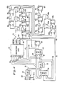
- Fig. 4 illustrates a maximum likelihood detector system 11 for performing the steps of process 10.
- Detector system 11 includes an input data bus 100 which receives data from a conventional analog-to-digital converter (not shown). The converted signal is scaled so that the magnitude of a nominal "1" sample is equal to the weight of the second most significant digit thereof. For purposes of this specification, converted signals are assumed to be in offset binary.
- Periodic samples of an original pseudo-ternary output signal from a communication or recording channel are received by the analog-to-digital converter and applied to k-bit latch 86 via input bus 100 in a parallel, six bit, binary form.
- Latch 86 thus receives six bits of sample information at each clock sample occurrence on clock line 102.
- Six bits provide near optimal resolution, since using fewer than six bits does not result in adequate resolution, and using more than six bits does not significantly improve resolution.
- Clock line 102 also clocks all sequential circuitry to synchronize overall operation of detector system 11.
- Sample bus 88 is six bits wide which is subsequently divided into bus 89 for receiving four bits, and lines 90a,b for receiving one bit each.
- Line 90a carries the high order bit, S0, of sample bus 88 and line 90b carries the second highest order bit, S1, of sample bus 88.
- Lines 90a,b respectively, apply the two highest order bits of sample bus 88 to combinational logic 94.
- the remaining four low order bits of sample bus 88 are applied by bus 89 to k-2 bit magnitude comparator 112.
- k-bit latch 116 stores a six bit binary representation of the magnitude of the estimator E. This estimator E is the value which is recorded as the current most likely "1".
- the output of latch 116 is six bit estimator bus 118.
- the four low order bits of estimator bus 118 are applied by bus 119 to k-2 bit magnitude comparator 112.
- the two high order bits of estimator bus 118 are applied to combinational logic 94 by lines 92a,b.
- Line 92a applies the high order bit, E0, of estimator bus 118 to combinational logic 94 and line 92b applies the second highest order bit, E1, to combinational logic 94.
- combinational logic 94 determines whether a new sample S should become an estimator E, whether a most likely "1" should be confirmed as a true “1", and whether process 10 should switch from one search mode to the other according to the decisions of diamonds 13, 16, 24 and 28 of Fig. 1. Combinational logic 94 is fully described and specified by Table I of this specification (see below).
- any steps of process 10 which may be completed by comparing the two high order bits only of the sample S with those of the estimator E are resolved by combinational logic 94 on the basis of the bit patterns on lines 90a,b and lines 92a,b. For example, in searching for a positive 1, if SO and S1 are 11 and E0 and E1 are 10, 01 or 00, combinational logic 94 can make the determination that the sample S is greater than the estimator E as shown in diamond 13 of Fig. 1 and that the sample falls within region 42. Since the two high order bits of sample bus 88, SO and S1, have a greater magnitude than the two high order bits, E0 and E1, of the estimator bus 118, the new sample S is greater than the estimator E regardless of the value of the four low order bits. Likewise, if lines 90a,b, which carry SO and S1 respectively, are 10 and lines 92a,b, which carry E0 and E1 respectively, are 01 or 00, combinational logic 94 can determine that the sample S is greater than the estimator E.
- combinational logic 94 requires information from the four low order bits of sample bus 88 and the four low order bits of estimator bus 118 to determine whether the sample S is greater than the estimator E.
- Magnitude comparator 112 compares the four low order bits of sample bus 88, which are applied to comparator 112 on bus 89, with the four low order bits of estimator bus 118, which are applied to comparator 112 by bus 119.
- the state of line 110 may be used by combinational logic 94 to determine whether the difference between the magnitudes of the sample S and estimator E is greater than the nominal sample amplitude, A, when the magnitude of the sample S does not exceed the magnitude of the estimator E. From this determination, it is known whether the sample falls within region 44 or region 46 (see Fig. 2) while process 10 is searching for the most likely positive "1" and whether the sample S falls within region 76 or region 78 (see Fig. 3) while process 10 is searching for the most likely negative "1".
- the second most significant bit is selected to be the nominal amplitude, a 100% overrange capability for the analog-to-digital conversion is provided.
- the weight of S1 and E1 the second most significant bit of the sample S and the estimator E respectively, represents the magnitude, A
- the relative magnitude comparison of diamond 16 may be implemented by combinational logic 94 without the propagation delay caused by adders and subtractors.
- the estimator E exceeds the sample S by more than the nominal sample amplitude A.
- the full six bit value of the estimator E may range from 110000 to 111111 when E0 and E1 are 11 and the full six bit value of the sample S may range from 100000 to 101111 when S0 and S1 are 10.
- the maximum possible difference between the estimator E and the sample S a difference of 011111, occurs when the estimator E is 111111 and the sample S is 100000.
- the difference between the sample S and the estimator E may range from 000001 to 011111.
- the value of A, 010000, falls within this range and the difference between the sample S and the estimator E may be greater than A or less than A. Therefore, the relative magnitude of the sample S and the estimator E cannot be resolved on the basis of the high order bits alone and the signal applied by line 110 to combinational logic 94 is used to resolve the comparison.
- combinational logic 94 All operations performed within combinational logic 94 are performed to determine the states of CONFIRM line 96, POINTER line 104 and NEXTPOL line 106.
- the states of CONFIRM line 96, POINTER line 104 and NEXTPOL 106 are shown in Table I for all states of the six input lines of combinational logic 94.
- Combinational logic 94 may be implemented using a conventional ROM having a capacity of at least sixty-four words with a length of three bits. Also, as indicated earlier in this specification, combinational logic 94 may be implemented using random logic according to Table I.
- POINTER line 104 goes high when a new sample S on sample bus 88 is greater than the estimator E which is stored in latch 116.
- POINTER line 104 is applied to k-bit multiplexer 114.
- k-bit multiplexer 114 causes the data on sample bus 88 to appear on bus 115.
- Bus 115 applies this data to k-bit latch 116.
- the output of latch 116 forms six bit estimator bus 118, the four low order bits of which are applied to bit magnitude comparator 112 and the two high order bits of which are applied to combinational logic 94 as previously described.
- the current sample S on sample bus 88 is latched into latch 116 when POINTER line 104 is high, thereby becoming the estimator, and operation k ⁇ n of block 14 is implemented.
- Inverter 120 inverts the signal level on POINTER line 104 and applies the inverted POINTER line 104 signal on line 122 to latches 108b-e through AND gates 130a-d. This action causes a "0" to be entered into latches 108b-e when the "1" is entered into latch 108a. Thus, all latches 108a-e are reset except for latch 108a when POINTER line 104 goes high.
- the "1" which is entered into 108a shifts through latches 103b-e during successive clock cycles. It thus marks the bit position of the current most likely "1" and latches 108a-e serve as a shift register containing a single "1" which points to the bit position of the most likely "1". This bit position corresponds to bit k.
- Each latch 108a-e points to a corresponding latch 98a-e through AND gates 126a-e.
- latch 108a points to latch 98a through AND gate 126a
- latch 108d points to latch 98d through AND gate 126d.
- latches 108a-d are pointer latches in which each latch 108a-d except one stores a "0".
- CONFIRM line 96 goes high.
- CONFIRM line 96 is applied to AND gates 126a-e.
- the outputs of pointer latches 108a-e respectively, are also applied to AND gates 126a-e as previously described.
- a high level on CONFIRM line 96 causes AND gates 126a-e to gate the contents of each latch 108a-e into its corresponding latch 98a-e.
- latches 108a-e contain "0" in all locations except the location corresponding to the bit position of the most likely "1"
- a single “1” is transferred to latches 98a-e through AND gates 126a-e.
- This single “1” is the "1” which was confirmed in combinational logic 94 causing CONFIRM line 96 to go high.
- OR gates 128a-d allow previously confirmed “1”'s to continue shifting through latches 98a-e when "0"'s from latches 108a-d are gated through AND gates 126a-e to latches 98a-e by a high level on CONFIRM line 96.
- combinational logic 94 After combinational logic 94 confirms a most likely "1" and gates the contents of latches 103a-e through to latches 98a-e, detector system 11 switches mode and begins searching for a "1" of the opposite polarity.
- NEXTPOL line 106 which indicates that the polarity of the next mode is to be searched, therefore, goes high and toggles latch 80 causing latch 80 to change state.
- the output of latch 80 is applied by line 82 to combinational logic 94 to indicate the change in polarity.
- the use of a separate latch 80 for toggling the polarity allows the logic within logic 94 to be purely combinational.
- combinational logic 94 uses the two high order bits of sample bus 88, the two high order bits of estimator bus 118, and line 110 from comparator 112 as previously described.
- the shift registers In considering the length of the shift registers formed by latches 108a-e and by latches 98a-e required for detector system 11 to implement process 10, it can be seen that a most likely "1" in latches 108a-e which represents a true “1” must be confirmed and gated to latches 98a-d before it is shifted through latches 108a-e. Therefore, the shift registers must be of sufficient length that a pointer representing a true "1" does not reach the end until it is confirmed. The number of latches in the shift registers must be one more than the maximum run length of "0"'s in the input data. Thus, the shift register length is determined by maximum run length of "0"'s of the pseudo-ternary code which is applied to detector system 11. This run length constraint must be applied to ensure correct detection with a finite length shift register.
Landscapes
- Engineering & Computer Science (AREA)
- Theoretical Computer Science (AREA)
- Physics & Mathematics (AREA)
- Probability & Statistics with Applications (AREA)
- Dc Digital Transmission (AREA)
- Compression, Expansion, Code Conversion, And Decoders (AREA)
Applications Claiming Priority (2)
| Application Number | Priority Date | Filing Date | Title |
|---|---|---|---|
| US75901285A | 1985-07-24 | 1985-07-24 | |
| US759012 | 1985-07-24 |
Publications (2)
| Publication Number | Publication Date |
|---|---|
| EP0209839A2 true EP0209839A2 (de) | 1987-01-28 |
| EP0209839A3 EP0209839A3 (de) | 1989-07-05 |
Family
ID=25054045
Family Applications (1)
| Application Number | Title | Priority Date | Filing Date |
|---|---|---|---|
| EP86109713A Withdrawn EP0209839A3 (de) | 1985-07-24 | 1986-07-15 | Vorrichtung und Verfahren zur Dekodierung einer Folge pseudoternärer digitaler Signale |
Country Status (2)
| Country | Link |
|---|---|
| EP (1) | EP0209839A3 (de) |
| JP (1) | JPS6225516A (de) |
Cited By (3)
| Publication number | Priority date | Publication date | Assignee | Title |
|---|---|---|---|---|
| FR2612025A1 (fr) * | 1987-03-06 | 1988-09-09 | Labo Electronique Physique | Dispositif de decodage de signaux codes en duobinaire |
| EP0474185A1 (de) * | 1990-09-07 | 1992-03-11 | Alcatel Business Systems | Numerischer Datendekoder, nach einem bipolaren Markinvertierenden Kode kodiert |
| CN110266314A (zh) * | 2019-07-25 | 2019-09-20 | 中北大学 | 一种集中序列生成器 |
Families Citing this family (1)
| Publication number | Priority date | Publication date | Assignee | Title |
|---|---|---|---|---|
| US7328304B2 (en) * | 2004-02-27 | 2008-02-05 | Intel Corporation | Interface for a block addressable mass storage system |
Family Cites Families (4)
| Publication number | Priority date | Publication date | Assignee | Title |
|---|---|---|---|---|
| US3026375A (en) * | 1958-05-09 | 1962-03-20 | Bell Telephone Labor Inc | Transmission of quantized signals |
| US3126537A (en) * | 1961-12-29 | 1964-03-24 | trampel | |
| CA1091810A (en) * | 1976-12-16 | 1980-12-16 | Toshio Koga | Predictive codec capable of selecting one of at least three prediction signals in two steps |
| US4571734A (en) * | 1983-08-05 | 1986-02-18 | International Business Machines Corporation | Method and apparatus for decoding the output signal of a partial-response class-IV communication or recording-device channel |
-
1986
- 1986-07-11 JP JP16221286A patent/JPS6225516A/ja active Pending
- 1986-07-15 EP EP86109713A patent/EP0209839A3/de not_active Withdrawn
Cited By (6)
| Publication number | Priority date | Publication date | Assignee | Title |
|---|---|---|---|---|
| FR2612025A1 (fr) * | 1987-03-06 | 1988-09-09 | Labo Electronique Physique | Dispositif de decodage de signaux codes en duobinaire |
| EP0283077A1 (de) * | 1987-03-06 | 1988-09-21 | Laboratoires D'electronique Philips | Einrichtung zur Dekodierung duobinärer kodierter Signale |
| EP0474185A1 (de) * | 1990-09-07 | 1992-03-11 | Alcatel Business Systems | Numerischer Datendekoder, nach einem bipolaren Markinvertierenden Kode kodiert |
| FR2668320A1 (fr) * | 1990-09-07 | 1992-04-24 | Alcatel Business Systems | Decodeur pour un signal binaire code selon un code bipolaire a inversion de marque. |
| CN110266314A (zh) * | 2019-07-25 | 2019-09-20 | 中北大学 | 一种集中序列生成器 |
| CN110266314B (zh) * | 2019-07-25 | 2022-10-04 | 中北大学 | 一种集中序列生成器 |
Also Published As
| Publication number | Publication date |
|---|---|
| EP0209839A3 (de) | 1989-07-05 |
| JPS6225516A (ja) | 1987-02-03 |
Similar Documents
| Publication | Publication Date | Title |
|---|---|---|
| US6493162B1 (en) | Frame synchronization for viterbi detector | |
| US6751774B2 (en) | Rate (M/N) code encoder, detector, and decoder for control data | |
| EP0593763B1 (de) | Dekodierungsverfahren maximaler wahrscheinlichskeit und vorrichtung zur bewertung | |
| JPH05128737A (ja) | デジタル位相誤差予測器 | |
| US6678862B1 (en) | Detection apparatus | |
| US5774286A (en) | Magnetic disk drive in which read data is demodulated using maximum likelihood detection method | |
| US5384560A (en) | Maximum likelihood sequence metric calculator | |
| JP4303165B2 (ja) | パイプライン方式のビタビデコーダ | |
| US7069481B2 (en) | Data recovery circuit for minimizing power consumption by non-integer times oversampling | |
| US6480984B1 (en) | Rate (M/N) code encoder, detector, and decoder for control data | |
| KR100661761B1 (ko) | 데이터 디코딩 장치 및 데이터 디코딩 방법 | |
| EP0209839A2 (de) | Vorrichtung und Verfahren zur Dekodierung einer Folge pseudoternärer digitaler Signale | |
| US6608871B2 (en) | Data slicers | |
| US6798726B2 (en) | Data decoding | |
| JPH06188749A (ja) | 適応ビテルビ検出器 | |
| EP0751518B1 (de) | Schaltung zur Bestimmung des Justierbits | |
| US6580766B1 (en) | Partial response maximum likelihood (PRML) bit detection apparatus | |
| KR100740190B1 (ko) | 채널 신호로부터 수신된 신호의 검출 방법 및 장치 | |
| JPH09247137A (ja) | 位相誤差検出回路及びデジタルpll回路 | |
| JP2001217716A (ja) | ディジタル・システム用の効率的アナログ/ディジタル変換器並びにその方法 | |
| KR100463560B1 (ko) | 비대칭 채널 데이터 검출 보상 장치 | |
| US6963625B2 (en) | Dada decoding | |
| US6542103B2 (en) | Error signal generating arrangement | |
| JPH07262708A (ja) | 位相同期回路 | |
| JPH06349207A (ja) | 情報再生装置 |
Legal Events
| Date | Code | Title | Description |
|---|---|---|---|
| PUAI | Public reference made under article 153(3) epc to a published international application that has entered the european phase |
Free format text: ORIGINAL CODE: 0009012 |
|
| AK | Designated contracting states |
Kind code of ref document: A2 Designated state(s): DE FR GB IT |
|
| 17P | Request for examination filed |
Effective date: 19870529 |
|
| PUAL | Search report despatched |
Free format text: ORIGINAL CODE: 0009013 |
|
| STAA | Information on the status of an ep patent application or granted ep patent |
Free format text: STATUS: THE APPLICATION HAS BEEN WITHDRAWN |
|
| AK | Designated contracting states |
Kind code of ref document: A3 Designated state(s): DE FR GB IT |
|
| 18W | Application withdrawn |
Withdrawal date: 19890629 |
|
| RIN1 | Information on inventor provided before grant (corrected) |
Inventor name: TURNER, DAVID PRICE Inventor name: EGGENBERGER, JOHN SCOTT |