EP0209903B1 - Platten-Antriebsgerät - Google Patents
Platten-Antriebsgerät Download PDFInfo
- Publication number
- EP0209903B1 EP0209903B1 EP86110152A EP86110152A EP0209903B1 EP 0209903 B1 EP0209903 B1 EP 0209903B1 EP 86110152 A EP86110152 A EP 86110152A EP 86110152 A EP86110152 A EP 86110152A EP 0209903 B1 EP0209903 B1 EP 0209903B1
- Authority
- EP
- European Patent Office
- Prior art keywords
- center
- drive pin
- disk
- driving
- drive
- Prior art date
- Legal status (The legal status is an assumption and is not a legal conclusion. Google has not performed a legal analysis and makes no representation as to the accuracy of the status listed.)
- Expired - Lifetime
Links
Images



Classifications
-
- G—PHYSICS
- G11—INFORMATION STORAGE
- G11B—INFORMATION STORAGE BASED ON RELATIVE MOVEMENT BETWEEN RECORD CARRIER AND TRANSDUCER
- G11B17/00—Guiding record carriers not specifically of filamentary or web form, or of supports therefor
- G11B17/22—Guiding record carriers not specifically of filamentary or web form, or of supports therefor from random access magazine of disc records
- G11B17/28—Guiding record carriers not specifically of filamentary or web form, or of supports therefor from random access magazine of disc records the magazine having a cylindrical shape with horizontal axis
-
- G—PHYSICS
- G11—INFORMATION STORAGE
- G11B—INFORMATION STORAGE BASED ON RELATIVE MOVEMENT BETWEEN RECORD CARRIER AND TRANSDUCER
- G11B17/00—Guiding record carriers not specifically of filamentary or web form, or of supports therefor
- G11B17/02—Details
- G11B17/022—Positioning or locking of single discs
- G11B17/028—Positioning or locking of single discs of discs rotating during transducing operation
- G11B17/0282—Positioning or locking of single discs of discs rotating during transducing operation by means provided on the turntable
-
- G—PHYSICS
- G11—INFORMATION STORAGE
- G11B—INFORMATION STORAGE BASED ON RELATIVE MOVEMENT BETWEEN RECORD CARRIER AND TRANSDUCER
- G11B19/00—Driving, starting, stopping record carriers not specifically of filamentary or web form, or of supports therefor; Control thereof; Control of operating function ; Driving both disc and head
- G11B19/20—Driving; Starting; Stopping; Control thereof
- G11B19/2009—Turntables, hubs and motors for disk drives; Mounting of motors in the drive
-
- G—PHYSICS
- G11—INFORMATION STORAGE
- G11B—INFORMATION STORAGE BASED ON RELATIVE MOVEMENT BETWEEN RECORD CARRIER AND TRANSDUCER
- G11B23/00—Record carriers not specific to the method of recording or reproducing; Accessories, e.g. containers, specially adapted for co-operation with the recording or reproducing apparatus ; Intermediate mediums; Apparatus or processes specially adapted for their manufacture
- G11B23/0014—Record carriers not specific to the method of recording or reproducing; Accessories, e.g. containers, specially adapted for co-operation with the recording or reproducing apparatus ; Intermediate mediums; Apparatus or processes specially adapted for their manufacture record carriers not specifically of filamentary or web form
- G11B23/0021—Record carriers not specific to the method of recording or reproducing; Accessories, e.g. containers, specially adapted for co-operation with the recording or reproducing apparatus ; Intermediate mediums; Apparatus or processes specially adapted for their manufacture record carriers not specifically of filamentary or web form discs
- G11B23/0028—Details
- G11B23/0035—Details means incorporated in the disc, e.g. hub, to enable its guiding, loading or driving
Definitions
- the present invention relates generally to a disk drive apparatus for rotating a disk, such as a floppy disk, a microfloppy disk and so forth. More specifically, the invention relates to a chucking mechanism for a disk drive, which can accurately position or center the disk.
- magnetic disks such as floppy disks, microfloppy disks and so forth, most commonly have a center aperture and a drive aperture offset from the center aperture.
- a disk drive is provided with a center positioning pin engageable to the center aperture of the disk, and a drive pin engageable to the drive aperture of the disk.
- the center positioning pin and the drive pin project from a turntable which is driven to rotate by means of a known drive mechanism.
- the disclosed flexible magnetic disk cassette has a flexible disk enclosed in a cassette casing made of an upper half and a lower half.
- the lower half has a drive hole through which a center positioning pin of a disk drive apparatus may extend into the center aperture of a center core disk rigidly and non- removably secured at the center of the disk.
- the center core disk also has a driving and positioning means for receiving a drive pin of the disk drive apparatus.
- the driving and positioning means is structured so that engagement with the drive pin will cause the disk to move until the center aperture of the attached center core disk is in proper centering engagement with the positioning pin.
- the disk drive apparatus comprises a center positioning pin and a spring-biased drive pin provided on a rotational drive.
- the center positioning pin is inserted in the center aperture means.
- the spring-biased drive pin is inserted in the driving and positioning aperature means during operation.
- the spring-biased drive pin is spring-biased so as to permit tilting of the pin to effect an at least partial radial displacement of at least the top of the pin in a vicinity of the driving and positioning aperture means when engaged with the positioning aperture.
- the prior-art disk drive apparatus discussed above encounters a drawback in that the rotational torque that can be applied to the disk is limited.
- the spring-biased drive pin can no longer be biased toward the peripheral edge of an opening constituting the driving and positioning means, i.e. the biasing force exerted on the drive pin will no longer be sufficient to establish firm contact between the peripheral edge of the opening and the drive pin.
- the disk cannot be accurately centered.
- Document EP-A-152 266 discloses an other disc drive apparatus of the same type presenting rotary base means, a center pin and a drive pin wherein the drive pin is mounted on a base plate which is pivotably mounted on the rotary base means supporting the disc.
- Another object of the present invention is to provide a disk drive apparatus which can minimize displacement of the chucking point so as to prevent offset of the disk from a predetermined position.
- a further object of the invention is to provide a disk drive apparatus which reduces the shock of chucking and thus minimizes or eliminates wear and/or deformation of a drive opening and a drive pin.
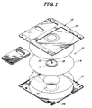
- a flexible magnetic disk cassette 10 which is applicable to the preferred embodiment of a disk drive apparatus according to the present invention has a cassette casing 12 housing a flexible magnetic disk 14.
- the magnetic disk 14 is made of, for example, a thin disk-like high-density polymer film 0.4 mm thick, and a magnetic layer uniformly deposited on both surfaces to which a recording and/or reproducing magnetic head can be brought into contact.
- a center core disk 16 is fixedly attached to the magnetic disk 14.
- the center core disk 16 is made of a ferromagnetic material, such as iron.
- the center core disk 16 has an essentially square center aperture 18 at its center.
- the center aperture 18 is designed to receive a motor shaft 20 (shown in Fig. 3) of a disk drive device.
- An essentially rectangular driving and positioning aperture 22 is formed at a predetermined distance from the center aperture 18.
- the driving and positioning aperture 22 receives a drive pin 24 of the disk drive device.
- the center aperture 18 and the driving and positioning aperture 22 are so arranged that the diagonals of the square center aperture lie parallel to the sides of the driving and positioning aperture.
- the sides of the center aperture 18 are slightly longer than the diameter of the motor shaft 20 so that the motor shaft fits loosely in the center aperture. This permits the axis of the center aperture to be slightly offset from the center axis of the center core disk 16.
- the cassette casing 12 comprises an upper half 26 and a lower half 28, both, for example, injection molded from ABS resin containing an antistatic agent.
- the upper and lower halves 26 and 28 are assembled to define an internal space which rotatably accommodates the magnetic disk 14.
- the lower half 28 has a center opening 30 near its center.
- the center core disk 16 is exposed through the center opening 30 of the lower half 28.
- the disk drive apparatus has a turntable assembly 40 on which the magnetic disk cassette 10 can be mounted.
- the turntable assembly 40 comprises a rotary base 42, a center pin 44, a drive pin 46, a drive pin support 48, a spring 50, a magnet plate 52, and a bearing sheet 54.
- the rotary base 42 is of a substantially disc-shaped configuration.
- the rotary base 42 has a center boss section 56.
- the rotary base 42 fixedly engages a motor shaft 20 of a disk drive motor (not shown), which extends vertically and firmly engages the center boss section 56 to transmit the driving force of the disk drive motor. Therefore, the rotary base 42 is driven to rotate by the disk drive motor.
- the rotary base 42 also has an essentially rectangular opening 58.
- the magnet plate 52 is essentially C-shaped and is made of magnetizable elastic or the like. The magnet plate 52 is fastened or bonded to the upper surface of the rotary base 42 so as to surround the center boss section 56.
- the bearing sheet 54 is made of a non-magnetic material and is in the form of an annular sheet matching the configuration and size of the uppermost face of the center boss section 56 of the rotary base 42. The bearing sheet 54 is fastened or bonded to the upper face of the center boss section 56 around the center pin 44.
- the drive pin support 48 is mounted beneath the rotary base 42.
- the drive pin support 48 is made of stainless steel or the like and is essentially annular.
- the drive pin support 48 has an essentially U-shaped, non-resilient section 60 and an adjoining essentially U-shaped, resilient section 62 forming the integral annular configuration.
- a pair of substantially straight sections 64 join the non-resilient section 60 and the resilient section 62.
- a resilient piece 68 integral with the cross bar of the "U" of the resilient section 62 extends therefrom oblique to the straight sections 64.
- the drive pin 46 is mounted upright on the resilient piece 68.
- An annular bearing 70 is mounted atop the drive pin 46.
- the drive pin support 48 opposes the lower surface of the rotary base 42 so that the drive pin 46 extends upward through the rectangular opening 58 in the rotary base 42.
- the rectangular opening 58 is positioned relative to the center pin 44 in essentially the same relationship that the driving and positioning aperture 22 has relative to the center aperture 18 of the magnetic disk cassette 10.
- a pivot 72 pivotally supports the drive pin support 48 beneath the rotary base 42.
- the pivot 72 comprises a stem section 74 and a base section 76.
- the stem section 74 serves as a pivot axle of the drive pin support 48.
- the stem section 74 thus extends through an opening 78 in the non-resilient section 60 of the drive pin support 48 and engages an opening 80 through the rotary base 42.
- the opening 78 in the drive pin support 48 is offset from the drive pin 46 at an angle ⁇ 2 equal to about 900 in the direction opposite to the direction (represented by the arrow in Fig. 4) of rotation of the turntable assembly 40.
- a resilient spring 82 engages the stem section 74 of the pivot 72 by means of a press-fit recess 84.
- the resilient spring 82 is held between the lower surface of the drive pin support 48 and the upper surface of the base section 76 of the pivot.
- the resilient spring 82 exerts a resilient force biasing the drive pin support 48 toward the lower surface of the rotary base 42
- the top of the stem section 74 of the pivot 72 is caulked so as to couple the rotary base 42 to the drive pin support 48 and the resilient spring 82 while compressing the resilient spring.
- the drive pin 46 moves along the path indicated by arrows c and d in Fig. 4.
- the radial component of the travel of the drive pin 46 is greater than the angular component within the rectangular opening 58 of the rotary base 42. Therefore, the travel of the drive pin 46 within the rectangular opening 58 is predominantly radial as illustrated by the arrows c and d.
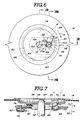
- the resilient section 62 of the drive pin support 48 can deform to allow pivotal movement of the drive pin relative to the vertical axis, as illustrated by arrows g and h in Fig. 7.
- the spring 50 is a coil spring connecting the rotary base 42 and the drive pin support 48.
- One end of the coil spring 50 engages a hooking opening 88 in the rotary base 42.
- the other end of the coil spring 50 engages a hook 90 of the drive pin support 48 extending from the non-resilient section 60.
- the coil spring 50 is accommodated by a cutout 92 in the outer periphery of the rotary base 42.
- the coil spring 50 urges the drive pin support 48 and the drive pin 46 to rotate in the direction indicated by arrow d in Fig. 4, i.e., it tends to drive the drive pin 46 away from the center of the rotary base 42.
- a microfloppy disc cassette 40 is placed on the turntable assembly 40 with the aid of the center aperture 18 and the driving and positioning aperture 20 of the center core disk 16 of the magnetic disk cassette 10, as shown in Figs. 6 to 9.
- the center core disk 16 is drawn against the bearing sheet 54 by the magnetic attraction of the magnet plate 52.
- the center core disk 16 will push the drive pin downward, causing deformation of the resilient piece 64 of the drive pin support and downward shifting of the drive pin.
- the axis of the drive pin 46 inclines relative to the vertical in the direction indicated by arrow h in Fig. 7 against the resilient force of the leaf spring 82.
- the drive pin 46 abuts the lower surface of the center core disk 16 against the force of the resilient piece 64 and the resilient spring 82.
- the drive pin 46 shifts in the direction of arrow e with respect to the center core disk 16 until it is aligned with the driving and positioning aperture 20 of the center core disk 16.
- the drive pin 46 becomes free to move in the direction indicated by arrow g in Fig. 7, and thus loosely engages the driving and positioning aperture 20 due to the force of the resilient spring 82 and the resilient piece 64.
- the drive pin 46 rotating with the rotary base 42 drives the magnetic disk 14 to rotate in the direction e.
- the drive pin 46 also pushes the driving and positioning aperture 22 in the direction e.
- the center pin 44 is pressed against the two edges of the center aperture 18.
- the magnetic disk 14 is accurately centered and firmly fixed on the rotary base 42 for rotation therewith. This condition of the magnetic disk 14 will be hereafter referred to as "chucking position".
- the chucking position, at which the drive pin 46 chucks the center core disk 16, is retained by the balance of forces urging the center pin 44 against the peripheral edges of the center aperture 18 and urging the drive pin against the outer and front side peripheral edges of the driving and positioning aperture 22.
- the tracks can be recorded at fixed locations on the disk.
- the drive pin 46 inclines to an angle of about 450 with respect to the radius of the turntable assembly 40 (arrow i) so that the function of the combination of the resilient section 62 of the drive pin support 48 and the resilient piece 64 permits the drive pin 46 to escape from the outer and front side peripheral edges of the driving and positioning aperture 22.
- the drive pin support 48 is essentially annular, the strength of the resilient section 62 of the drive pin support is sufficient to hold the drive pin 46 essentially vertical. Accordingly, the drive pin 46 can be inclined in the direction labelled i and then return quickly in the direction i' to its vertical position drawn in the phantom lines of Figs. 7 to 9, wherein the drive pin 46 occupies its normal position perpendicular to the center core disk 16 within the driving and positioning aperture 22 so as to drive the magnetic disk 14.
- the angular offset ⁇ 2 of the pivot 72 with respect to the drive pin 46 is limited in no way to 900 but may be any desired angle permitting the drive pin 46 to move predominantly radially.
- the annular shape of the drive pin support 48 and the shape of the resilient section 62 of the drive pin support may be modified to any desired configuration appropriate for implementing the desired operation explained above.
- the present invention is not limited to use in microfloppy disk drive apparatus, but is applicable to various recording and/or reproducing disk drive apparatus.
Landscapes
- Holding Or Fastening Of Disk On Rotational Shaft (AREA)
Claims (7)
- Magnetplattantriebsgerät für den Drehantrieb einer Magnetplatte mit einer zentralen Positionierungsöffnung (18) und einer gegenüber dieser um einen vorgegebenen Abstand versetzten Antriebs- und Positionierungsöffnung (22),
wobei das Gerät aufweist:
einen zentralen Stift (44), der mit der zentralen Positionierungsöffnung (18) in Eingriff bringbar ist,
einen Antriebsstift (46), der mit der Antriebs- und Positionierungsöffnung (22) in Eingriff bringbar ist,
eine drehbare Basisanordnung (42) zur Halterung des zentralen Stifts (44) in einer im wesentlichen zentralen Position, die mit dem zentralen Stift (44) rotiert und eine ebene Oberseite zur Halterung der Magnetplatte (14) besitzt,
und ein Antriebsstift-Trägermittel (48) zur Halterung des Antriebsstifts (46) in einer Position, die im wesentlichen der Antriebs- und Positionierungsöffnung (22) entspricht, wobei dieses Antriebsstift-Trägermittel (48) an der drehbaren Basisanordnung (42) schwenkbar montiert ist, derart daß es eine Schwenkbewegung in einer Ebene ausführen kann, im wesentlichen parallel zur Oberseite der drehbaren Basisanordnung (42) verläuft,
dadurch gekennzeichnet,
daß das Antriebsstift-Trägermittel (48) verformbar ist, um eine Neigung der Achse des Antriebsstifts (46) relativ zu einer zur Achse des zentralen Stifts (44) parallelen Achse in einer von der Umfangsrichtung abweichenden Richtung zu ermöglichen. - Magnetplattenantriebsgerät nach Anspruch 1, dadurch gekennzeichnet, daß das Antriebsstift-Trägermittel (48) ein elastisches Glied (62) aufweist, das elastisch verformbar ist, um eine Neigung der Achse des Antriebsstifts herbeizuführen.
- Magnetplattenantriebsgerät nach Anspruch 1 oder 2, dadurch gekennzeichnet, daß das Antriebsstift-Trägermittel (48) elastische Eigenschaft besitzt, um eine Neigung der Achse des Antriebsstifts in radialer Richtung herbeizuführen.
- Magnetplattenantriebsgerät nach einem der Ansprüche 1 bis 3, dadurch gekennzeichnet, daß das Antriebsstift-Trägermittel (48) relativ zu der drehbaren Basisanordnung (42) verschwenkbar ist, um eine Bewegung des Antriebsstifts (46) in einer von der Umfangsrichtung abweichenden Richtung herbeizuführen.
- Magnetplattenantriebsgerät nach Anspruch 3 oder 4, dadurch gekennzeichnet, daß die Bewegung des Antriebsstifts (46) eine radiale Komponente aufweist, um den Antriebsstift (46) relativ zu dem zentralen Stift (44) zu verschieben und den relativen radialen Abstand zwischen ihnen zu verändern.
- Magnetplattenantriebsgerät nach Anspruch 5, gekennzeichnet durch seine Anpassung für den Antrieb der genannten Magnetplatte (14) mit der zentralen Positionierungsöffnung (18), die eine erste und eine zweite Zentrierkante (18a, 18b) besitzt, die an dem zentralen Stift (44) zur Anlage kommen, und der Antriebs- und Positionierungsöffnung (22), die eine Zentrierkante und eine Antriebskante besitzt, die an dem Antriebsstift (46) zur Anlage kommen, wobei das Antriebsstift-Trägermittel (48) eine Schwenkbewegung ausführt, um den relativen radialen Abstand zwischen dem zentralen Stift (44) und dem Antriebsstift (46) zu verändern und den Eingriff zwischen dem zentralen Stift (44) und der ersten und der zweiten Zentrierkante (18a, 18b) der zentralen Positionierungsöffnung (18) und zwischen dem Antriebsstift (46) und der Zentrierkante und der Antriebskante der Antriebs- und Positionierungsöffnung (22) zu verspannen.
- Kombination aus einer Kassette (10) für eine flexible Magnetplatte und einem für deren Antrieb bestimmten Magnetplattenantriebsgerät nach einem der Ansprüche 1 bis 6, wobei die Kassette aufweist:
eine flexible Magnetplatte (14),
eine die flexible Magnetplatte (14) enthaltende Abdeckung (12) mit einer Antriebsöffnung (22), durch das hindurch die flexible Magnetplatte (14) antreibbar ist, und
eine zentrale Kernscheibe (16), die im Zentrum der flexiblen Magnetplatte (14) starr und unbeweglich befestigt ist und die die genannte zentrale Positionierungsöffnung (18) mit der ersten und der mit dieser konvergierenden zweiten Zentrierkante (18a, 18b) sowie die genannte Antriebs- und Positionierungsöffnung (22) mit der Positionierungs- und der Antriebskante aufweist.
Applications Claiming Priority (2)
| Application Number | Priority Date | Filing Date | Title |
|---|---|---|---|
| JP60162272A JPH0743865B2 (ja) | 1985-07-23 | 1985-07-23 | デイスクの回転駆動装置 |
| JP162272/85 | 1985-07-23 |
Publications (3)
| Publication Number | Publication Date |
|---|---|
| EP0209903A2 EP0209903A2 (de) | 1987-01-28 |
| EP0209903A3 EP0209903A3 (en) | 1988-09-28 |
| EP0209903B1 true EP0209903B1 (de) | 1992-02-19 |
Family
ID=15751307
Family Applications (1)
| Application Number | Title | Priority Date | Filing Date |
|---|---|---|---|
| EP86110152A Expired - Lifetime EP0209903B1 (de) | 1985-07-23 | 1986-07-23 | Platten-Antriebsgerät |
Country Status (8)
| Country | Link |
|---|---|
| US (1) | US4989107A (de) |
| EP (1) | EP0209903B1 (de) |
| JP (1) | JPH0743865B2 (de) |
| KR (1) | KR950001829B1 (de) |
| CA (1) | CA1311047C (de) |
| DE (1) | DE3683918D1 (de) |
| HK (1) | HK46395A (de) |
| SG (1) | SG26495G (de) |
Families Citing this family (19)
| Publication number | Priority date | Publication date | Assignee | Title |
|---|---|---|---|---|
| US5461523A (en) * | 1988-08-12 | 1995-10-24 | Canon Denshi Kabushiki Kaisha | Disc unit having a drive motor and a chucking assembly for holding a disc therewith |
| WO1990003031A1 (en) * | 1988-09-05 | 1990-03-22 | Seiko Epson Corporation | Recording/reproducing apparatus |
| US5161075A (en) * | 1988-09-28 | 1992-11-03 | Kabushiki Kaisha Sankyo Seiki Seisakusho | Hub table for a magnetic disk drive device |
| US5689388A (en) * | 1989-06-15 | 1997-11-18 | Canon Denshi Kabushiki Kaisha | Reduced-height magnetic disk drive unit, and disk mounting device for the unit |
| JP2811824B2 (ja) * | 1989-11-08 | 1998-10-15 | ソニー株式会社 | デイスクチヤツキング装置 |
| JPH0416653U (de) * | 1990-05-31 | 1992-02-12 | ||
| US5247409A (en) * | 1990-10-26 | 1993-09-21 | Teac Corporation | Disk drive pin support mechanism in a rotating disk data storage apparatus |
| JPH0481239U (de) * | 1990-11-22 | 1992-07-15 | ||
| JPH087559Y2 (ja) * | 1991-06-21 | 1996-03-04 | ティアック株式会社 | ディスク装置 |
| US5610779A (en) * | 1991-09-06 | 1997-03-11 | Matsushita Electric Industrial Co., Ltd. | Floppy disk drive |
| US5323286A (en) * | 1992-12-31 | 1994-06-21 | Xerox Corporation | Method of determining tape length and tape pack position of a tape cassette |
| JP2516157Y2 (ja) * | 1993-09-29 | 1996-11-06 | ミツミ電機株式会社 | ディスクドライバ |
| KR970055900U (ko) * | 1996-03-28 | 1997-10-13 | 플로피 디스크 드라이브의 디스크 구동용 구동레버 | |
| KR100223210B1 (ko) | 1996-11-09 | 1999-10-15 | 윤종용 | 하드디스크 드라이브의 디스크 균형을 맞추기 위한 조립방법 및 장치 |
| JP3750701B2 (ja) * | 1996-11-19 | 2006-03-01 | ミツミ電機株式会社 | ディスクホールド機構およびそれを備えたディスク装置 |
| CA2243786A1 (en) * | 1997-07-31 | 1999-01-31 | Yasushi Tomita | Recording medium and disc cartridge |
| JP2011046154A (ja) | 2009-08-28 | 2011-03-10 | Fuji Xerox Co Ltd | 画像処理装置、印刷システム及びプログラム |
| CN101783154B (zh) * | 2010-03-16 | 2012-08-22 | 杨东佐 | 一种具有光盘夹持机构的光盘读取机芯 |
| US8991711B2 (en) | 2012-07-19 | 2015-03-31 | Infineon Technologies Ag | Chip card module |
Family Cites Families (15)
| Publication number | Priority date | Publication date | Assignee | Title |
|---|---|---|---|---|
| JPS5736473A (en) * | 1980-08-14 | 1982-02-27 | Sony Corp | Rotating driving device |
| JPS606938Y2 (ja) * | 1980-08-14 | 1985-03-07 | ソニー株式会社 | 記録再生用デイスクカセツト |
| JPS57164891U (de) * | 1981-04-08 | 1982-10-18 | ||
| JPS5954089A (ja) * | 1982-09-22 | 1984-03-28 | Hitachi Ltd | 回転デイスク保持装置 |
| JPS5987677A (ja) * | 1982-11-11 | 1984-05-21 | Matsushita Electric Ind Co Ltd | 可撓性磁気デイスク装置 |
| US4613921A (en) * | 1982-11-26 | 1986-09-23 | Holmes William A | Disk memory apparatus |
| JPS603950U (ja) * | 1983-06-20 | 1985-01-12 | セイコーエプソン株式会社 | 磁気デイスク駆動装置のデイスク固定機構 |
| JPS60164953A (ja) * | 1984-02-06 | 1985-08-28 | Sony Corp | デイスクの回転駆動装置 |
| JPS60140258U (ja) * | 1984-02-27 | 1985-09-17 | ティアック株式会社 | デイスク駆動装置 |
| JPS60256982A (ja) * | 1984-06-01 | 1985-12-18 | Sankyo Seiki Mfg Co Ltd | デイスクの回転駆動装置 |
| JPS619866A (ja) * | 1984-06-22 | 1986-01-17 | Seiko Epson Corp | 回転駆動装置 |
| JPS6121050U (ja) * | 1984-07-06 | 1986-02-06 | 蛇の目ミシン工業株式会社 | 磁気記録再生装置のインデツクス信号発生機構 |
| JPS6154073A (ja) * | 1984-08-23 | 1986-03-18 | Tokyo Juki Ind Co Ltd | 磁気記録媒体の位置決め機構 |
| IT1179839B (it) * | 1984-11-30 | 1987-09-16 | Olivetti & Co Spa | Dispositivo per portare in rotazione un disco magnetico |
| US4667257A (en) * | 1985-11-18 | 1987-05-19 | Chan Industries, Inc. | Disk drive and centering mechanism for microfloppy disk drive |
-
1985
- 1985-07-23 JP JP60162272A patent/JPH0743865B2/ja not_active Expired - Lifetime
-
1986
- 1986-07-17 US US06/887,080 patent/US4989107A/en not_active Expired - Lifetime
- 1986-07-17 CA CA000514081A patent/CA1311047C/en not_active Expired - Lifetime
- 1986-07-23 KR KR1019860005970A patent/KR950001829B1/ko not_active Expired - Lifetime
- 1986-07-23 EP EP86110152A patent/EP0209903B1/de not_active Expired - Lifetime
- 1986-07-23 DE DE8686110152T patent/DE3683918D1/de not_active Expired - Lifetime
-
1995
- 1995-02-17 SG SG26495A patent/SG26495G/en unknown
- 1995-03-30 HK HK46395A patent/HK46395A/en not_active IP Right Cessation
Also Published As
| Publication number | Publication date |
|---|---|
| SG26495G (en) | 1995-08-18 |
| US4989107A (en) | 1991-01-29 |
| KR870001594A (ko) | 1987-03-14 |
| CA1311047C (en) | 1992-12-01 |
| KR950001829B1 (ko) | 1995-03-03 |
| EP0209903A3 (en) | 1988-09-28 |
| HK46395A (en) | 1995-04-07 |
| JPS6222270A (ja) | 1987-01-30 |
| JPH0743865B2 (ja) | 1995-05-15 |
| EP0209903A2 (de) | 1987-01-28 |
| DE3683918D1 (de) | 1992-03-26 |
Similar Documents
| Publication | Publication Date | Title |
|---|---|---|
| US4989107A (en) | Microfloppy disk drive with centering mechanism | |
| US4445155A (en) | Flexible magnetic disk cassette and a recording and/or reproducing apparatus for the same | |
| CA1177163A (en) | Flexible magnetic disk cassette | |
| JP3384002B2 (ja) | ディスクテーブル及び記録及び/又は再生装置 | |
| US4630156A (en) | Flexible magnetic disc including hub structure | |
| US4697216A (en) | Disk drive apparatus with automatic centering arrangement | |
| GB2101390A (en) | Magnetic disc assemblies. | |
| JPH02141956A (ja) | デイスクの回転駆動装置 | |
| US4812937A (en) | Magnetic disk cartridge with improved center plate for disk mounting | |
| US4672486A (en) | Apparatus for rotating a magnetic disc | |
| JP2811824B2 (ja) | デイスクチヤツキング装置 | |
| JPS6341645Y2 (de) | ||
| EP0246298B1 (de) | Antriebsmechanismus für speicherplatte und nabe | |
| US4983439A (en) | Method of manufacturing a recording medium and recording medium | |
| JPS606913Y2 (ja) | 記録再生用デイスクカセツト | |
| US5796547A (en) | Disk cartridge and drive mechanism thereof | |
| US6259582B1 (en) | Chucking device in FDD | |
| US4864442A (en) | Magnetic read/write apparatus | |
| JPS633019Y2 (de) | ||
| JPH05205432A (ja) | ディスクカートリッジ及びディスク駆動装置 | |
| JPH039164Y2 (de) | ||
| JP2592078B2 (ja) | ディスクチャッキング機構 | |
| JPH0743866B2 (ja) | デイスク駆動装置 | |
| JPS63204572A (ja) | デイスク装置 | |
| JPH0480463B2 (de) |
Legal Events
| Date | Code | Title | Description |
|---|---|---|---|
| PUAI | Public reference made under article 153(3) epc to a published international application that has entered the european phase |
Free format text: ORIGINAL CODE: 0009012 |
|
| AK | Designated contracting states |
Kind code of ref document: A2 Designated state(s): DE FR GB NL |
|
| PUAL | Search report despatched |
Free format text: ORIGINAL CODE: 0009013 |
|
| AK | Designated contracting states |
Kind code of ref document: A3 Designated state(s): DE FR GB NL |
|
| 17P | Request for examination filed |
Effective date: 19890328 |
|
| 17Q | First examination report despatched |
Effective date: 19900808 |
|
| GRAA | (expected) grant |
Free format text: ORIGINAL CODE: 0009210 |
|
| AK | Designated contracting states |
Kind code of ref document: B1 Designated state(s): DE FR GB NL |
|
| REF | Corresponds to: |
Ref document number: 3683918 Country of ref document: DE Date of ref document: 19920326 |
|
| ET | Fr: translation filed | ||
| PLBE | No opposition filed within time limit |
Free format text: ORIGINAL CODE: 0009261 |
|
| STAA | Information on the status of an ep patent application or granted ep patent |
Free format text: STATUS: NO OPPOSITION FILED WITHIN TIME LIMIT |
|
| 26N | No opposition filed | ||
| REG | Reference to a national code |
Ref country code: GB Ref legal event code: IF02 |
|
| PGFP | Annual fee paid to national office [announced via postgrant information from national office to epo] |
Ref country code: NL Payment date: 20050703 Year of fee payment: 20 |
|
| PGFP | Annual fee paid to national office [announced via postgrant information from national office to epo] |
Ref country code: FR Payment date: 20050708 Year of fee payment: 20 |
|
| PGFP | Annual fee paid to national office [announced via postgrant information from national office to epo] |
Ref country code: GB Payment date: 20050720 Year of fee payment: 20 |
|
| PGFP | Annual fee paid to national office [announced via postgrant information from national office to epo] |
Ref country code: DE Payment date: 20050721 Year of fee payment: 20 |
|
| PG25 | Lapsed in a contracting state [announced via postgrant information from national office to epo] |
Ref country code: GB Free format text: LAPSE BECAUSE OF EXPIRATION OF PROTECTION Effective date: 20060722 |
|
| PG25 | Lapsed in a contracting state [announced via postgrant information from national office to epo] |
Ref country code: NL Free format text: LAPSE BECAUSE OF EXPIRATION OF PROTECTION Effective date: 20060723 |
|
| REG | Reference to a national code |
Ref country code: GB Ref legal event code: PE20 |
|
| NLV7 | Nl: ceased due to reaching the maximum lifetime of a patent |
Effective date: 20060723 |