EP0210133A2 - Dispositif pour doser et égaliser un film de liquide sur un rouleau d'une machine à imprimer - Google Patents
Dispositif pour doser et égaliser un film de liquide sur un rouleau d'une machine à imprimer Download PDFInfo
- Publication number
- EP0210133A2 EP0210133A2 EP86810319A EP86810319A EP0210133A2 EP 0210133 A2 EP0210133 A2 EP 0210133A2 EP 86810319 A EP86810319 A EP 86810319A EP 86810319 A EP86810319 A EP 86810319A EP 0210133 A2 EP0210133 A2 EP 0210133A2
- Authority
- EP
- European Patent Office
- Prior art keywords
- roller
- belt
- liquid
- rotating roller
- endless belt
- Prior art date
- Legal status (The legal status is an assumption and is not a legal conclusion. Google has not performed a legal analysis and makes no representation as to the accuracy of the status listed.)
- Granted
Links
Images

Classifications
-
- B—PERFORMING OPERATIONS; TRANSPORTING
- B41—PRINTING; LINING MACHINES; TYPEWRITERS; STAMPS
- B41F—PRINTING MACHINES OR PRESSES
- B41F31/00—Inking arrangements or devices
- B41F31/20—Ink-removing or collecting devices
Definitions
- the invention relates to a device for fine metering and balancing a liquid film created by a liquid application device on a rotating roller of a printing press with a liquid-permeable fine metering belt which loops around the rotating roller and strips off the excess ink, which in turn runs into a catch basin, the liquid application device being used every revolution of the rotating roller completely renews the liquid film.
- Such a device is shown in DE-OS 2146045, in which a gauze is stretched against the ductor roller by a roller inking unit of an office offset printing machine for metering the amount of ink on the duct roller.
- the duct roller has a substantially lower peripheral speed than the cylinder on which the printing form is arranged. For this reason, it is necessary to arrange a lifting roller after the duct roller.
- This siphon roller takes on the ink at the same peripheral speed as the duct roller rotates and transfers it to a 1st inking roller which has the same peripheral speed as the printing form cylinder.
- DE-OS 28 12 998 shows a roller that directly colors the printing plate of the plate cylinder. This roller is forced to have a soft, rubber-elastic surface. The ink applied to the roller by an ink fountain is stripped off by an ink knife in such a way that the ink film has the thickness necessary for further processing.
- the inking roller with the rubber-elastic surface according to DE-OS 28 12 998 is preceded by an ink cylinder provided with a rigid surface, on which an ink film by means of metering elements is generated to avoid the strong elastic deformation of the soft surface of the roller.
- This additional inking roller which makes the whole arrangement more expensive, must have the exact same diameter as the plate cylinder, so that the appearance of so-called ghost images is prevented.
- An additional inking roller between the plate cylinder and the ink cylinder must be arranged to avoid two rollers with a hard surface coming into contact with each other.
- the ink film that is created on the inking roller is not completely balanced and renewed.
- the residual ink film not picked up by the plate cylinder and remaining on the inking roller is overlaid with new ink the next time it is touched with the ink cylinder, which is repeated with each new rotation. For this reason, dirt and unclean pressure can occur.
- This contamination can lead to the metering gap also becoming dirty, which leads to uneven ink supply and increased wear.
- With the contact line between the support body and the ink cylinder these dirt particles can also lead to increased wear.
- the risk of a backlog of color, which originates from the residual film that remains on the ink cylinder is very high and must somehow be derived.
- the object of the invention is to provide a device which makes it possible to produce a finely metered liquid film on a rotating roller with the least possible number of rollers, which film is created and compensated for every revolution of the rotating roller, and which further mentioned Avoids disadvantages.
- the object is achieved in that the rotating roller comes into contact with an axially parallel forme cylinder carrying a printing form, and thereby transfers the stripping belt, which is wrapped around the rotating roller, to the required amount of liquid film, which is necessary for further processing, on the printing form, the rotating roller having a circumferential speed which corresponds practically to that of the forme cylinder.
- the surface quality and the surface hardness of the rotating roller can be adapted in virtually any manner to the printing process, to the liquid to be processed or to the processing speed.
- the dosing screws and their expensive control device are omitted for fine dosing of the liquid film on the rotating roller.
- the quality of the belt can be varied practically as desired and adapted to the requirements of the work process, since between the scraper belt and the rotating roller, due to the hydrodynamic pressure at production speed, there is pure fluid friction and the wear is therefore very low.
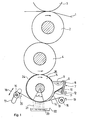
- Fig. 1 shows schematically a printing unit of a printing press, in which a paper web 1, which is printed, is passed in a known manner between a rubber cylinder 2 and an impression cylinder 3, which are rotatably mounted in a machine frame, not shown.
- a plate cylinder 4 is assigned to the blanket cylinder 2, from which the print image is transferred to the blanket cylinder 2.
- the plate cylinder 4 receives ink and / or dampening solution from a rotating roller 5.
- the rotating roller 5, like the blanket cylinder 2 and plate cylinder 4, is driven by a known device (not shown), the peripheral speeds being the same.
- the rotating roller 5 receives the liquid 6 from a liquid application device 7.
- This liquid application device 7 is limited, for example, on the one hand by a rear wall 8, side walls 9, metering knife 10 and, on the other hand, by the rotating roller 5.
- a gap 11 between metering knife 10 and rotating roller 5, its Width is set once by adjusting screws 12 at the start of operation, determines the film thickness 13 of the liquid which the rotating roller 5 takes with it.
- the tension of the scraper belt 14 can be varied with the brakeable unwinding shaft 15. Braked unwinding shaft 15 and drivable winding shaft 16 make it possible to replace, for example, a worn area of the stripping belt 14 by wrapping in the direction of the arrows 19 and 20 in the simplest way by a new area of the stripping belt 14, which can easily be done during operation of the printing press.
- the stripping belt 14 strips off the liquid adhering to the rotating roller 5, the stripped liquid 21 being guided away through the spaces and running into a collecting basin 22. From there, the liquid 23 passes through lines (not shown) into a known processing device. The remaining liquid film 24 is then the Plate cylinder 4 supplied. The then remaining liquid residue 25 is completely renewed in the liquid container 7.
- the blanket cylinder 2 can be replaced by an impression cylinder and the plate cylinder 4 by a plate or form cylinder corresponding to the type of printing, the web to be printed passing between these cylinders.
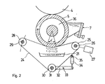
- 2 shows an embodiment of a device for the fine metering of a liquid film on a rotating roller 5, the stripping belt 14 being designed as an endless belt 24. This endless belt 24 is guided over rollers.
- the drivable roller 25 is firmly seated on a rotatable, stationary shaft 26 which is driven by a continuously variable motor 27.
- the pivotable roller 28 in turn sits on a shaft 29, the position of which can be changed to adjust the wrap angle ⁇ .
- a tensionable roller 30 is freely rotatable on an axis 31.
- the axis 31 is stuck in one end of a lever 32 which can be rotated about a fixed axis 33.
- the other end of the lever 32 is connected in an articulated manner to a pressure cylinder 34 which is rotatably articulated on a fixed pin 35.
- this pressure cylinder 34 With the help of this pressure cylinder 34, the required tension of the endless belt 24 is achieved by adjusting the pressurizing pressure of the medium.
- the rotating roller 5 is provided with a cavity 36, which enables cooling of the rotating roller 5 which may be necessary.
- the device shown in FIG. 3 is also provided with an endless belt 24, like the embodiment shown in FIG. 2.
- the endless belt 24 runs over a drivable roller 37, a pivotable roller 38 and a tensionable roller 39.
- the drivable roller 37 is driven by a continuously variable motor 27.
- Another roller 41 which is arranged on a stationary shaft 42, lies in the region of a cleaning basin 43 which is filled with a cleaning agent 44. When not in use, the cleaning basin 43 can be lowered into a lower layer 45 (shown in dashed lines).
- the belt outlet runs through a device 46 or 47, which removes unnecessary cleaning agent from the endless belt 24, for example by wiping it off.
- the device 46 or 47 is in engagement, depending on the running direction of the endless belt 24. This arrangement also makes it possible to clean the rotating roller 5.
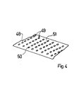
- the base material consists of a film 48, which can be, for example, metallic or plastic, the side of which facing the rotating roller 5 has a smooth surface, and which is provided with a number of rows of holes 49.
- the oval holes 50 for example, allow the liquid stripped by the webs 51 remaining between them to run away and to flow into the collecting basin 22.
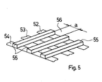
- FIG. 5 shows a further embodiment of the stripping belt used for the device described.
- Webs 55 are arranged on inextensible but flexible band strips 52, 53, 54, which are at a mutual distance a.
- the space 56 formed in this way allows that the liquid stripped off by the webs 55 can run away and reaches the catch basin 22 (FIG. 1).
- All the adjustment devices of this invention can of course be automated, for example the various setting variables are stored in a control unit and the various programs can thus be run.
- the entire scraper belt holder and / or liquid container can be accommodated in boxes which have lateral boundaries and can therefore be easily replaced.
- the width of the boxes can be such that several boxes can be arranged across the roll width.
Landscapes
- Inking, Control Or Cleaning Of Printing Machines (AREA)
- Coating Apparatus (AREA)
- Measuring Or Testing Involving Enzymes Or Micro-Organisms (AREA)
- Investigating Or Analysing Biological Materials (AREA)
Priority Applications (1)
| Application Number | Priority Date | Filing Date | Title |
|---|---|---|---|
| AT86810319T ATE58335T1 (de) | 1985-07-23 | 1986-07-15 | Vorrichtung zum feindosieren eines fluessigkeitsfilms auf einer rotierenden walze einer druckmaschine. |
Applications Claiming Priority (2)
| Application Number | Priority Date | Filing Date | Title |
|---|---|---|---|
| DE19853526308 DE3526308A1 (de) | 1985-07-23 | 1985-07-23 | Vorrichtung zum feindosieren eines fluessigkeitsfilms auf einer rotierenden walze einer druckmaschine |
| DE3526308 | 1985-07-23 |
Publications (3)
| Publication Number | Publication Date |
|---|---|
| EP0210133A2 true EP0210133A2 (fr) | 1987-01-28 |
| EP0210133A3 EP0210133A3 (en) | 1988-07-20 |
| EP0210133B1 EP0210133B1 (fr) | 1990-11-14 |
Family
ID=6276518
Family Applications (1)
| Application Number | Title | Priority Date | Filing Date |
|---|---|---|---|
| EP86810319A Expired - Lifetime EP0210133B1 (fr) | 1985-07-23 | 1986-07-15 | Dispositif pour doser et égaliser un film de liquide sur un rouleau d'une machine à imprimer |
Country Status (8)
| Country | Link |
|---|---|
| EP (1) | EP0210133B1 (fr) |
| JP (1) | JPS6264550A (fr) |
| AT (1) | ATE58335T1 (fr) |
| CA (1) | CA1280033C (fr) |
| CH (1) | CH670421A5 (fr) |
| DE (1) | DE3526308A1 (fr) |
| FI (1) | FI81998C (fr) |
| IN (1) | IN166256B (fr) |
Cited By (1)
| Publication number | Priority date | Publication date | Assignee | Title |
|---|---|---|---|---|
| FR2614835A1 (fr) * | 1987-05-05 | 1988-11-10 | Wifag Maschf | Mecanisme d'encrage pour une machine d'impression |
Family Cites Families (6)
| Publication number | Priority date | Publication date | Assignee | Title |
|---|---|---|---|---|
| DE2146045A1 (de) * | 1971-09-15 | 1973-03-29 | Roto Werke Gmbh | Walzenfarbwerk fuer druckmaschinen |
| DE2538105C3 (de) * | 1974-09-11 | 1978-06-22 | Hans Jacob Dipl.-Ing. Oesteraas Moestue (Norwegen) | Waschvorrichtung eines Zylinders einer Druckmaschine |
| DE2555993C3 (de) * | 1975-12-12 | 1980-11-06 | Koenig & Bauer Ag, 8700 Wuerzburg | Farbkasten eines Farbwerkes |
| SE433829B (sv) * | 1977-03-21 | 1984-06-18 | Dahlgren Harold P | Forfarande och tryckfergsutmetningsapparat for utmetning av tryckferg |
| DE2856088A1 (de) * | 1978-12-23 | 1980-07-03 | Maschf Augsburg Nuernberg Ag | Farbwerk |
| DE3217569C2 (de) * | 1982-05-11 | 1985-11-28 | Heidelberger Druckmaschinen Ag, 6900 Heidelberg | Verfahren und Vorrichtung zum Dosieren der Farbe bei Offsetdruckmaschinen |
-
1985
- 1985-07-23 DE DE19853526308 patent/DE3526308A1/de active Granted
-
1986
- 1986-06-25 FI FI862701A patent/FI81998C/fi not_active IP Right Cessation
- 1986-06-26 IN IN561/DEL/86A patent/IN166256B/en unknown
- 1986-07-01 CH CH2636/86A patent/CH670421A5/de not_active IP Right Cessation
- 1986-07-15 EP EP86810319A patent/EP0210133B1/fr not_active Expired - Lifetime
- 1986-07-15 AT AT86810319T patent/ATE58335T1/de not_active IP Right Cessation
- 1986-07-22 JP JP61170960A patent/JPS6264550A/ja active Granted
- 1986-07-23 CA CA000514474A patent/CA1280033C/fr not_active Expired - Lifetime
Cited By (2)
| Publication number | Priority date | Publication date | Assignee | Title |
|---|---|---|---|---|
| FR2614835A1 (fr) * | 1987-05-05 | 1988-11-10 | Wifag Maschf | Mecanisme d'encrage pour une machine d'impression |
| US4917012A (en) * | 1987-05-05 | 1990-04-17 | Maschinenfabrik Wifag | Inking device for printing press and an inking dosing member construction |
Also Published As
| Publication number | Publication date |
|---|---|
| FI81998B (fi) | 1990-09-28 |
| EP0210133A3 (en) | 1988-07-20 |
| JPH0455594B2 (fr) | 1992-09-03 |
| IN166256B (fr) | 1990-03-31 |
| FI862701A0 (fi) | 1986-06-25 |
| CH670421A5 (fr) | 1989-06-15 |
| JPS6264550A (ja) | 1987-03-23 |
| EP0210133B1 (fr) | 1990-11-14 |
| FI862701L (fi) | 1987-01-24 |
| ATE58335T1 (de) | 1990-11-15 |
| FI81998C (fi) | 1991-01-10 |
| DE3526308A1 (de) | 1987-02-05 |
| CA1280033C (fr) | 1991-02-12 |
| DE3526308C2 (fr) | 1988-04-07 |
Similar Documents
| Publication | Publication Date | Title |
|---|---|---|
| EP0064270B1 (fr) | Dispositif d'encrage | |
| DE3903721C2 (de) | Rotations-Siebdruckmaschine | |
| DE1176674B (de) | Farbwerk fuer Rotationsdruckmaschinen | |
| DE2932105A1 (de) | Farbwerk fuer eine offsetrotationsdruckmaschine | |
| DE8413874U1 (de) | Vorrichtung zum Befeuchten an lithographischen Druckpressen | |
| DE10000903A1 (de) | Verfahren zum Betrieb einer Druckmaschine und Druckmaschine zur Durchführung des Verfahrens | |
| DE2531886C3 (de) | Verfahren und Vorrichtung zur Reinigung von Zylindern eines Offsetdruckwerkes | |
| EP1013418B1 (fr) | Dispositif d'encrage | |
| EP0093879B1 (fr) | Procédé et dispositif de dosage d'encre dans les rotatives offset | |
| DE2259085A1 (de) | Farbwerk fuer flachdruckmaschinen | |
| EP0602431A1 (fr) | Dispositif de racle d'essuyage | |
| DE1285976B (de) | Filmdruckmaschine | |
| DE4424590C2 (de) | Einrichtung zur Reinigung eines Farbwerkes einer Offsetdruckmaschine | |
| EP1531043A1 (fr) | Procédé et dispositif pour déplacer une racle | |
| DE3714160A1 (de) | Farbwerk fuer eine druckmaschine | |
| DE3714936C2 (fr) | ||
| EP0210671B1 (fr) | Dispositif de mouillage pour machine à imprimer | |
| DE3843473A1 (de) | Feuchtwerk fuer offsetdruckmaschinen | |
| DE2812998A1 (de) | Verfahren und vorrichtung zum dosieren einer fluessigkeit auf einer walze | |
| EP0210133B1 (fr) | Dispositif pour doser et égaliser un film de liquide sur un rouleau d'une machine à imprimer | |
| DE10253194A1 (de) | Vorrichtung und Verfahren zum Einfärben der Walze einer Rotationsdruckmaschine | |
| CH652347A5 (de) | Vorrichtung zum aufbringen eines fluessigen bzw. halbfluessigen mediums auf die druckplatte einer druckmaschine, insbesondere offsetdruckmaschine. | |
| DE3324445A1 (de) | Farbdosiervorrichtung an buch- und offsetdruckmaschinen | |
| EP0518084A1 (fr) | Presse d'impression offset avec formation d'émulsion commandée | |
| EP0761432A1 (fr) | Dispositif de mouillage pour une machine à imprimer en offset |
Legal Events
| Date | Code | Title | Description |
|---|---|---|---|
| PUAI | Public reference made under article 153(3) epc to a published international application that has entered the european phase |
Free format text: ORIGINAL CODE: 0009012 |
|
| AK | Designated contracting states |
Kind code of ref document: A2 Designated state(s): AT BE FR GB IT NL SE |
|
| PUAL | Search report despatched |
Free format text: ORIGINAL CODE: 0009013 |
|
| AK | Designated contracting states |
Kind code of ref document: A3 Designated state(s): AT BE FR GB IT NL SE |
|
| 17P | Request for examination filed |
Effective date: 19881122 |
|
| 17Q | First examination report despatched |
Effective date: 19900410 |
|
| GRAA | (expected) grant |
Free format text: ORIGINAL CODE: 0009210 |
|
| AK | Designated contracting states |
Kind code of ref document: B1 Designated state(s): AT BE FR GB IT NL SE |
|
| REF | Corresponds to: |
Ref document number: 58335 Country of ref document: AT Date of ref document: 19901115 Kind code of ref document: T |
|
| ET | Fr: translation filed | ||
| GBT | Gb: translation of ep patent filed (gb section 77(6)(a)/1977) | ||
| ITF | It: translation for a ep patent filed | ||
| PGFP | Annual fee paid to national office [announced via postgrant information from national office to epo] |
Ref country code: SE Payment date: 19910610 Year of fee payment: 6 |
|
| PGFP | Annual fee paid to national office [announced via postgrant information from national office to epo] |
Ref country code: BE Payment date: 19910626 Year of fee payment: 6 |
|
| PGFP | Annual fee paid to national office [announced via postgrant information from national office to epo] |
Ref country code: AT Payment date: 19910628 Year of fee payment: 6 |
|
| PGFP | Annual fee paid to national office [announced via postgrant information from national office to epo] |
Ref country code: GB Payment date: 19910703 Year of fee payment: 6 |
|
| PGFP | Annual fee paid to national office [announced via postgrant information from national office to epo] |
Ref country code: FR Payment date: 19910705 Year of fee payment: 6 |
|
| PGFP | Annual fee paid to national office [announced via postgrant information from national office to epo] |
Ref country code: NL Payment date: 19910731 Year of fee payment: 6 |
|
| PLBE | No opposition filed within time limit |
Free format text: ORIGINAL CODE: 0009261 |
|
| STAA | Information on the status of an ep patent application or granted ep patent |
Free format text: STATUS: NO OPPOSITION FILED WITHIN TIME LIMIT |
|
| 26N | No opposition filed | ||
| PG25 | Lapsed in a contracting state [announced via postgrant information from national office to epo] |
Ref country code: GB Effective date: 19920715 Ref country code: AT Effective date: 19920715 |
|
| PG25 | Lapsed in a contracting state [announced via postgrant information from national office to epo] |
Ref country code: SE Effective date: 19920716 |
|
| PG25 | Lapsed in a contracting state [announced via postgrant information from national office to epo] |
Ref country code: BE Effective date: 19920731 |
|
| BERE | Be: lapsed |
Owner name: MASCHINENFABRIK WIFAG Effective date: 19920731 |
|
| PG25 | Lapsed in a contracting state [announced via postgrant information from national office to epo] |
Ref country code: NL Effective date: 19930201 |
|
| NLV4 | Nl: lapsed or anulled due to non-payment of the annual fee | ||
| GBPC | Gb: european patent ceased through non-payment of renewal fee |
Effective date: 19920715 |
|
| PG25 | Lapsed in a contracting state [announced via postgrant information from national office to epo] |
Ref country code: FR Effective date: 19930331 |
|
| REG | Reference to a national code |
Ref country code: FR Ref legal event code: ST |
|
| EUG | Se: european patent has lapsed |
Ref document number: 86810319.3 Effective date: 19930204 |
|
| PG25 | Lapsed in a contracting state [announced via postgrant information from national office to epo] |
Ref country code: IT Free format text: LAPSE BECAUSE OF NON-PAYMENT OF DUE FEES Effective date: 20050715 |