EP0212456A2 - Appareil se déplaçant dans un tube - Google Patents
Appareil se déplaçant dans un tube Download PDFInfo
- Publication number
- EP0212456A2 EP0212456A2 EP86110885A EP86110885A EP0212456A2 EP 0212456 A2 EP0212456 A2 EP 0212456A2 EP 86110885 A EP86110885 A EP 86110885A EP 86110885 A EP86110885 A EP 86110885A EP 0212456 A2 EP0212456 A2 EP 0212456A2
- Authority
- EP
- European Patent Office
- Prior art keywords
- piping
- continuous
- wall surface
- treads
- frame
- Prior art date
- Legal status (The legal status is an assumption and is not a legal conclusion. Google has not performed a legal analysis and makes no representation as to the accuracy of the status listed.)
- Granted
Links
Images



Classifications
-
- G—PHYSICS
- G21—NUCLEAR PHYSICS; NUCLEAR ENGINEERING
- G21C—NUCLEAR REACTORS
- G21C17/00—Monitoring; Testing ; Maintaining
- G21C17/017—Inspection or maintenance of pipe-lines or tubes in nuclear installations
-
- F—MECHANICAL ENGINEERING; LIGHTING; HEATING; WEAPONS; BLASTING
- F16—ENGINEERING ELEMENTS AND UNITS; GENERAL MEASURES FOR PRODUCING AND MAINTAINING EFFECTIVE FUNCTIONING OF MACHINES OR INSTALLATIONS; THERMAL INSULATION IN GENERAL
- F16L—PIPES; JOINTS OR FITTINGS FOR PIPES; SUPPORTS FOR PIPES, CABLES OR PROTECTIVE TUBING; MEANS FOR THERMAL INSULATION IN GENERAL
- F16L55/00—Devices or appurtenances for use in, or in connection with, pipes or pipe systems
- F16L55/26—Pigs or moles, i.e. devices movable in a pipe or conduit with or without self-contained propulsion means
- F16L55/28—Constructional aspects
- F16L55/30—Constructional aspects of the propulsion means, e.g. towed by cables
-
- F—MECHANICAL ENGINEERING; LIGHTING; HEATING; WEAPONS; BLASTING
- F16—ENGINEERING ELEMENTS AND UNITS; GENERAL MEASURES FOR PRODUCING AND MAINTAINING EFFECTIVE FUNCTIONING OF MACHINES OR INSTALLATIONS; THERMAL INSULATION IN GENERAL
- F16L—PIPES; JOINTS OR FITTINGS FOR PIPES; SUPPORTS FOR PIPES, CABLES OR PROTECTIVE TUBING; MEANS FOR THERMAL INSULATION IN GENERAL
- F16L55/00—Devices or appurtenances for use in, or in connection with, pipes or pipe systems
- F16L55/26—Pigs or moles, i.e. devices movable in a pipe or conduit with or without self-contained propulsion means
- F16L55/28—Constructional aspects
- F16L55/30—Constructional aspects of the propulsion means, e.g. towed by cables
- F16L55/32—Constructional aspects of the propulsion means, e.g. towed by cables being self-contained
-
- F—MECHANICAL ENGINEERING; LIGHTING; HEATING; WEAPONS; BLASTING
- F16—ENGINEERING ELEMENTS AND UNITS; GENERAL MEASURES FOR PRODUCING AND MAINTAINING EFFECTIVE FUNCTIONING OF MACHINES OR INSTALLATIONS; THERMAL INSULATION IN GENERAL
- F16L—PIPES; JOINTS OR FITTINGS FOR PIPES; SUPPORTS FOR PIPES, CABLES OR PROTECTIVE TUBING; MEANS FOR THERMAL INSULATION IN GENERAL
- F16L2101/00—Uses or applications of pigs or moles
- F16L2101/30—Inspecting, measuring or testing
-
- Y—GENERAL TAGGING OF NEW TECHNOLOGICAL DEVELOPMENTS; GENERAL TAGGING OF CROSS-SECTIONAL TECHNOLOGIES SPANNING OVER SEVERAL SECTIONS OF THE IPC; TECHNICAL SUBJECTS COVERED BY FORMER USPC CROSS-REFERENCE ART COLLECTIONS [XRACs] AND DIGESTS
- Y02—TECHNOLOGIES OR APPLICATIONS FOR MITIGATION OR ADAPTATION AGAINST CLIMATE CHANGE
- Y02E—REDUCTION OF GREENHOUSE GAS [GHG] EMISSIONS, RELATED TO ENERGY GENERATION, TRANSMISSION OR DISTRIBUTION
- Y02E30/00—Energy generation of nuclear origin
- Y02E30/30—Nuclear fission reactors
Definitions
- This invention relates to piping travelling apparatus, and more particularly it is concerned with a piping travelling apparatus suitable for use in travelling through piping of relatively small diameter, such as gas distribution pipes, which has different levels in wall surface at pipe joints and elevations and depressions at many locations and which includes vertical or slanted pipe elements.
- the self-propelled vehicle having articulated arms which is capable of travelling while overcoming by its articulated arms any obstacle that might lie in the path of its travel can travel through not only piping but also a narrow space forming a multiple layer structure.
- the piping moving apparatus is intended for use in carrying out maintenance and inspection from inside heat transfer pipes of a nuclear power plant, for example, by inserting a probe for detecting flaws in the piping.
- the problem encountered in these systems of the prior art is that, although they are constructed to accommodate small variations in pipe diameter and negotiate gentle bends in piping, they lack the ability to travel along wavy surfaces and surfaces having changes in level and to negotiate sharp bends, so that they are unable to alter the direction of their travel by following a sharp bend or a branch at a junction.
- the invention has been developed for the purpose of obviating the aforesaid disadvantage of the prior art. Accordingly, the invention has as its object the provision of a piping travelling apparatus which has no difficulties in travelling through piping of relatively small diameter having elevations and depressions and changes in the level of its inner wall surface and including vertical or slanted pipes.
- the invention provides a piping travelling apparatus comprising a vehicle equipped with a plurality of continuous treads spaced apart peripherally of the inner wall surface of the piping, and drive motor means in the vehicle for driving the continuous treads to enable the vehicle to travel through the piping along the inner wall surface thereof.
- the vehicle may be equipped with continuous tread biasing means allowing the plurality of continuous treads to follow the inner wall surface of the piping peripherally thereof while forcing the continuous treads against the inner wall surface of the piping with a force of arbitrarily selected magnitude.
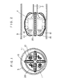
- Figs. 1 and 2 show one embodiment of the invention, in which the piping travelling apparatus comprises at least one vehicle 1 having a frame 20, a plurality of continuous treads 15 mounted to the frame 20 and a plurality of drive motors 10 in the frame 20 for driving the continuous treads 15.
- the drive motors 10 serving as a source of motive force transmit motive force through transmission gearing 11 to drive wheels 12 of the continuous treads 15.
- the vehicle 1 travels through piping 3 along an inner wall surface thereof as the continuous treads 15 are driven by the drive wheels 12.
- the vehicle 1 travels that at least one of the continuous treads 15 be maintained in contact with the inner wall surface of the piping 3, no matter what the posture of the vehicle 1 may be.
- the posture of the vehicle 1 undergoes changes.
- the vehicle 1 can negotiate the boundary between different levels on the inner wall surface of the piping 3 by the function of the continuous treads 15, no matter what the posture of the vehicle 1 may be.
- the continuous treads 15 are located on the periphery of the frame 20 in four positions and spaced apart a predetermined distance peripherally of the inner wall surface of the piping 3. This arrangement enables the vehicle 1 to smoothly negotiate the boundary between different levels on the inner wall surface of the piping 3 by the function of the continuous treads 15.
- the frame 20 which contains the drive unit for the continuous treads 15 avoids damage to the drive unit which might otherwise occur when the vehicle 1 collides with obstacles inside the piping 3 and prevents entry of foreign matter, such as dust or grits, from the piping 3 into the vehicle 1.
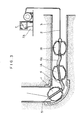
- Fig. 3 shows another embodiment of the invention, in which a plurality of vehicles are coupled together and sensor means for sensing the conditions in the piping 3 is mounted to provide a moving system for inspecting the inside of the piping 3.
- the plurality of vehicles are coupled together by means of coupling frames.
- the coupling frames used in this embodiment may be of any form as desired, such as flexible joints, universal joints, etc.
- an objective leans 5 is mounted at a forward end of the leading vehicle 1 to enable the conditions to be inspected by means of optical fibers.
- the objective lens 5 may be replaced by a fixed camera, flaw detector or any other suitable means.
- a leading vehicle 1 and an intermediate vehicle lA and the intermediate vehicle lA and a trailing vehicle lB are coupled together through coupling frames 4 and 4A, respectively, which may be flexible joints or universal joints as described hereinabove.
- the sensor means is connected to a control board 7A installed on the ground through a cable 2 for transmitting signals and supplying power.
- the operator drives the train of vehicles 1, lA and lB through the control panel 7A while monitoring the conditions in the piping 3 by watching a television screen 7 on the ground.
- the piping 3 has elbow joints bent at right angles, it is necessary that each vehicle have a total length great enough to negotiate the bend of each elbow joint.
- the train of vehicles has a long distance to travel through the piping 3 and the resistance offered by the cable 2 which is being pulled along the path of movement of the vehicles increases, necessary traction force is produced by the plurality of vehicles forming a train of vehicles.
- FIG. 4-7 Another embodiment of the invention comprising continuous tread biasing means mounted in the vehicle shown in Figs. 1 and 2 for biasing the continuous treads 15 into contact with the inner wall surface of the piping 3 with a force of arbitrarily selected magnitude will be described by referring to Figs. 4-7.
- Figs. 4-7 show one constructional form of continuous tread biasing means of the piping travelling apparatus according to the invention which comprises coil springs 16 for biasing the continuous treads 15 into contact with the inner wall surface of the piping 3, a spring holder 21 for supporting the coil springs 16 and securing same to the frame 20 of the vehicle 1 and coil springs 17 formed of shape memory alloy for controlling the biasing force of the coil springs 16.
- the continuous tread biasing means of this construction enables the continuous treads 15 which drive the vehicle 1 to be kept in contact with the inner wall surface of the piping 3 at all times when the vehicle 1 moves upwardly along inner wall surfaces of pipe elements which are vertical or slanted with respect to the horizontal, so that a frictional drag necessary to keep the vehicle 1 in position on the inner wall surface of the piping 3 can be produced.
- the continuous treads 15 do not slip when moving along wall surfaces of vertical pipe elements or steeply slanted pipe elements and enable the vehicle 1 to produce a traction force of high magnitude.
- the traction force produced by the vehicle 1 is proportional to the biasing force of the coil springs 16.
- the coil springs 16 preferably produce a high biasing force when the vehicle 1 is required to produce a high traction force as when the vehicle 1 has a flaw detector or a fiber-scope attached thereto during its travel.
- the high biasing force of the coil springs 16 needs to be reduced because, if the biasing force of the coil springs 16 is high, the traction force of the vehicle 1 necessary for moving from one level to another is high.
- the coil springs 17 formed of shape memory alloy are heated by heating means 18 when the vehicle 1 shifts from the level to another, so as to reduce the biasing force of the coil springs 16 or withdraw the continuous treads 15 fully into the frame 20 of the vehicle 1.
- Figs. 8 and 9 shows another constructional form of continuous tread biasing means comprising magnets.
- the continuous tread biasing means comprises a plurality of magnets 19 mounted on the entire surface of the continuous treads 15 so that the continuous treads 15 may be attracted to the inner wall surface of the piping 3.
- the continuous treads 15 which can move in sliding movement peripherally of the inner wall surface of the piping 3 enable the vehicle 1 to produce a traction force while being attracted to the inner wall surface of the piping 3 by the magnetic force of the magnets 19.
- the continuous treads 15 are attracted to the inner wall surface of the piping 3 by the magnetic force of the magnets 19 and enable the vehicle 1 to produce a traction force.
- This enables the continuous treads 15 to be kept in contact with the inner wall surface of the piping 3 at all times by a simple mechanism.
- the continuous treads 15 are prevented from separating themselves from the piping 3 by the magnetic force of the magnets 19 and enable the vehicle 1 to produce a fraction force.
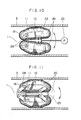
- Fig. 10 shows another constructional form of continuous tread biasing means comprising resilient pressure vessels.
- the continuous tread biasing means comprises resilient pressure vessels 22 each for forcing one of the continuous treads 15 against the inner wall surface of the piping 3, and means 23 for allowing a working fluid, such as a liquid or a gas, to flow into and out of the resilient pressure vessels 22.
- the continuous treads 15 which are superposed one above the other are mounted to the frame 20 of the vehicle 1 and each supported for pivotal movement about a rotary shaft 28 located in a plane inside the respective continuous tread 15.
- the upper and lower continuous treads 15 are biased in the directions of arrows into contact with the inner wall surface of the piping 3.
- the continuous treads 15 enable the vehicle 1 to produce a traction force of high magnitude even if there are different levels on the inner wall surface of the piping 3 along which it travels.
- Fig. 11 shows another embodiment of the invention in which the continuous treads 15 are mounted by parallel links pivotally supported at two points in a plane within the respective continuous treads 15.
- the continuous treads 15 shown in Fig. 11 are each supported by parallel links 24 pivoted at two points in a plane within the respective continuous treads 15.
- a plurality of plate springs 25 mounted between the two continuous treads 15 located in diametrically opposed positions force the continuous treads 15 against the inner wall surface of the piping 1 to enable the vehicle 1 to produce a necessary traction force.
- Fig. 12 shows a modification of the embodiment shown in Fig. 11 in which the drive motors 10 are supported separately in a drive motor frame 26.
- the vehicle 1 should have a small overall length and a small volume to smoothly move into a branch at a junction or negotiate the bend of an elbow without any trouble. Meanwhile it is necessary to increase the capacity of the drive motors 10 to increase the traction force produced by the vehicle 1 so that the vehicle 1 can smoothly travel through vertical or steeply slanted pipes.
- the drive motors 10 are supported in the drive motor frame 26 separately from the continuous tracks 15 and continuous track biasing means which are supported in the frame 20, and the drive motors connected to the continuous treads 15 through transmission gearing 11.
- Motive force is transmitted from the drive motors 10 to the continuous treads 15 through planetary gears of the transmission gearing 11 mounted to the parallel links 24.
- This arrangement enables motive force to be transmitted from the drive motors 10 to the continuous treads 15 which are kept in contact with the inner wall surface of the piping 3, thereby allowing the vehicle 1 to produce a necessary traction force.
- the piping travelling apparatus com strictlyprising at least one vehicle for travelling back and forth in the piping which is equipped with a plurality of continuous treads spaced apart a predetermined distance peripherally of the inner wall surface of the piping offers many advantages.
- the vehicle can travel without any trouble even if the piping has branches or bends and the inner wall surface of the piping has different levels at pipe joints or rises and falls at many locations. Even if the piping is relatively small in diameter or it has vertical or slanted pipes, the vehicle can travel smoothly without any trouble.
Landscapes
- Engineering & Computer Science (AREA)
- General Engineering & Computer Science (AREA)
- Chemical & Material Sciences (AREA)
- Combustion & Propulsion (AREA)
- Mechanical Engineering (AREA)
- Physics & Mathematics (AREA)
- Plasma & Fusion (AREA)
- High Energy & Nuclear Physics (AREA)
- Investigating Or Analyzing Materials By The Use Of Ultrasonic Waves (AREA)
- Analysing Materials By The Use Of Radiation (AREA)
- Investigating Materials By The Use Of Optical Means Adapted For Particular Applications (AREA)
- Cleaning In General (AREA)
Applications Claiming Priority (2)
| Application Number | Priority Date | Filing Date | Title |
|---|---|---|---|
| JP60172339A JPH07108659B2 (ja) | 1985-08-07 | 1985-08-07 | 管内走行装置、及び管内点検走行装置 |
| JP172339/85 | 1985-08-07 |
Publications (3)
| Publication Number | Publication Date |
|---|---|
| EP0212456A2 true EP0212456A2 (fr) | 1987-03-04 |
| EP0212456A3 EP0212456A3 (en) | 1987-10-14 |
| EP0212456B1 EP0212456B1 (fr) | 1990-11-07 |
Family
ID=15940068
Family Applications (1)
| Application Number | Title | Priority Date | Filing Date |
|---|---|---|---|
| EP86110885A Expired - Lifetime EP0212456B1 (fr) | 1985-08-07 | 1986-08-06 | Appareil se déplaçant dans un tube |
Country Status (4)
| Country | Link |
|---|---|
| US (1) | US4770105A (fr) |
| EP (1) | EP0212456B1 (fr) |
| JP (1) | JPH07108659B2 (fr) |
| DE (1) | DE3675462D1 (fr) |
Cited By (7)
| Publication number | Priority date | Publication date | Assignee | Title |
|---|---|---|---|---|
| GB2214263A (en) * | 1988-01-26 | 1989-08-31 | Kubota Ltd | Pipe pig |
| WO1991011652A1 (fr) * | 1990-02-05 | 1991-08-08 | Canalcrab S.A. | Dispositif de traction pour appareil de controle, de traitement et d'intervention a l'interieur de canalisations |
| FR2660730A1 (fr) * | 1990-04-09 | 1991-10-11 | Gautheron Christophe | Vehicule autopropulse franchisseur d'obstacles pour des missions a l'interieur de canalisations. |
| WO2008010189A3 (fr) * | 2006-07-18 | 2008-04-24 | Gfl Mining Services Ltd | Véhicule |
| GB2483227A (en) * | 2010-08-31 | 2012-03-07 | Guy Wheater | Articulated wire-line hole finder |
| US9945196B2 (en) | 2013-02-28 | 2018-04-17 | Guy Wheater | Articulated wireline hole finder |
| IT202000015586A1 (it) * | 2020-06-29 | 2021-12-29 | Marco Ceccarelli | Sistema per ispezione tubi a sezione variabile |
Families Citing this family (53)
| Publication number | Priority date | Publication date | Assignee | Title |
|---|---|---|---|---|
| US5090259A (en) * | 1988-01-18 | 1992-02-25 | Olympus Optical Co., Ltd. | Pipe-inspecting apparatus having a self propelled unit |
| JPH02162153A (ja) * | 1988-11-07 | 1990-06-21 | Sumitomo Metal Ind Ltd | 管内駆動台車 |
| JP2617137B2 (ja) * | 1989-11-09 | 1997-06-04 | 東京瓦斯 株式会社 | 管内駆動台車 |
| JPH03153458A (ja) * | 1989-11-09 | 1991-07-01 | Tokyo Gas Co Ltd | 自走式管内面検査装置 |
| US5018451A (en) * | 1990-01-05 | 1991-05-28 | The United States Of America As Represented By The United States Department Of Energy | Extendable pipe crawler |
| FR2662989A1 (fr) * | 1990-06-11 | 1991-12-13 | Esstin | Vehicule auto propulse et articule a verins telescopiques pour l'inspection de tuyauteries. |
| US5121694A (en) * | 1991-04-02 | 1992-06-16 | Zollinger William T | Pipe crawler with extendable legs |
| US5284096A (en) * | 1991-08-06 | 1994-02-08 | Osaka Gas Company, Limited | Vehicle for use in pipes |
| US5220869A (en) * | 1991-08-07 | 1993-06-22 | Osaka Gas Company, Ltd. | Vehicle adapted to freely travel three-dimensionally and up vertical walls by magnetic force and wheel for the vehicle |
| JP3155034B2 (ja) * | 1991-09-17 | 2001-04-09 | セイコーインスツルメンツ株式会社 | 超音波モータを用いた小型移動装置 |
| US5601025A (en) * | 1992-09-23 | 1997-02-11 | Martin Marietta Energy Systems, Inc. | Robotic vehicle |
| US5497707A (en) * | 1992-09-23 | 1996-03-12 | Martin Marietta Energy Systems, Inc. | Robotic vehicle |
| US5377237A (en) * | 1993-04-05 | 1994-12-27 | General Electric Company | Method of inspecting repaired stub tubes in boiling water nuclear reactors |
| US6087830A (en) * | 1994-07-07 | 2000-07-11 | Hydroscope Canada Inc. | Flexible device for remote field eddy current inspection of ferrous pipeline containing turns |
| US5675251A (en) * | 1994-07-07 | 1997-10-07 | Hydroscope Inc. | Device and method for inspection of pipelines |
| US5551349A (en) * | 1995-06-29 | 1996-09-03 | The United States Of America As Represented By The Secretary Of The Navy | Internal conduit vehicle |
| US5794703A (en) * | 1996-07-03 | 1998-08-18 | Ctes, L.C. | Wellbore tractor and method of moving an item through a wellbore |
| GB9614761D0 (en) | 1996-07-13 | 1996-09-04 | Schlumberger Ltd | Downhole tool and method |
| WO1998012418A2 (fr) | 1996-09-23 | 1998-03-26 | Intelligent Inspection Corporation Commonwealth Of Massachusetts | Outil de fond autonome pour gisement petrolifere |
| DE19746510C2 (de) * | 1997-10-22 | 2003-03-06 | Pii Pipetronix Gmbh | Vorrichtung zum Durchfahren von Rohrleitungen |
| US5992247A (en) * | 1998-04-23 | 1999-11-30 | Aries Industries Incorporated | Apparatus for inspecting lateral sewer pipes |
| US6359434B1 (en) | 1998-09-30 | 2002-03-19 | Hydroscope Cananda Inc. | Method and system for determining pipeline circumferential and non-circumferential wall loss defects in a water pipeline |
| US6450104B1 (en) | 2000-04-28 | 2002-09-17 | North Carolina State University | Modular observation crawler and sensing instrument and method for operating same |
| CA2309018A1 (fr) | 2000-05-12 | 2001-11-12 | R. Michael Mcgrew | Appareil ameliore d'inspection des egouts lateraux |
| US7445616B2 (en) * | 2001-03-23 | 2008-11-04 | Petrakis Dennis N | Temperature responsive systems |
| US7655001B2 (en) * | 2001-03-23 | 2010-02-02 | Petrakis Dennis N | Temperature responsive systems |
| GB0227383D0 (en) * | 2002-11-23 | 2002-12-31 | Univ Durham | Conduit traversing vehicle |
| US7143659B2 (en) | 2002-12-17 | 2006-12-05 | Pinnacle West Capital Corporation | Pipe-inspection system |
| US7476224B2 (en) * | 2003-03-17 | 2009-01-13 | Petrakis Dennis N | Temperature responsive systems |
| US7044245B2 (en) * | 2003-06-17 | 2006-05-16 | Science Applications International Corporation | Toroidal propulsion and steering system |
| US7156192B2 (en) * | 2003-07-16 | 2007-01-02 | Schlumberger Technology Corp. | Open hole tractor with tracks |
| US7073979B2 (en) * | 2003-11-26 | 2006-07-11 | Aries Industries Incorporated | Method and apparatus for performing sewer maintenance with a thermal sensor |
| US7348892B2 (en) * | 2004-01-20 | 2008-03-25 | Halliburton Energy Services, Inc. | Pipe mounted telemetry receiver |
| WO2005071216A1 (fr) | 2004-01-26 | 2005-08-04 | Chain Train | Outil de repechage destine a etre utilise dans des materiels tubulaires et des trous de forage pour la production de petrole et de gaz |
| US7188568B2 (en) * | 2005-06-29 | 2007-03-13 | Arizona Public Service Company | Self-propelled vehicle for movement within a tubular member |
| GB2430018A (en) * | 2005-09-13 | 2007-03-14 | Graeme Mcnay | Use of magnetic force for traction for internal crawling type deployment systems for ferrous piping |
| JP5101043B2 (ja) * | 2006-06-05 | 2012-12-19 | オリンパス株式会社 | 管内走行装置 |
| US7954575B1 (en) * | 2008-09-10 | 2011-06-07 | Bloxsom Joel O | Leader string pull-through machine |
| US20140054525A1 (en) | 2011-01-25 | 2014-02-27 | Jelcer-Ip B.V. | Pipe Travelling Apparatus and Use Thereof |
| CN102700636A (zh) * | 2012-05-30 | 2012-10-03 | 上海大学 | 辅助搜救设备进入废墟或管道内部的履带式驱动装置 |
| US9657542B2 (en) * | 2012-11-01 | 2017-05-23 | Saudi Arabian Oil Company | Wireline crawler tractor |
| US9719315B2 (en) * | 2013-11-15 | 2017-08-01 | Ge Oil & Gas Esp, Inc. | Remote controlled self propelled deployment system for horizontal wells |
| US20150184468A1 (en) * | 2013-12-30 | 2015-07-02 | Trican Well Service, Ltd. | Tractor for installing tubing encapsulated cable into coil tubing |
| CN104554501A (zh) * | 2015-01-07 | 2015-04-29 | 上海大学 | 狭小空间履带式驱动装置 |
| US10078031B2 (en) | 2016-02-16 | 2018-09-18 | Massachusetts Institute Of Technology | Compliant leak detection system |
| CN109069937A (zh) * | 2016-04-20 | 2018-12-21 | 米耶公司 | 配置成穿过非直线管状件段信件的自动重力辅助机动化赛车 |
| JP6716824B2 (ja) * | 2016-09-21 | 2020-07-01 | 株式会社ハイボット | 配管内移動装置 |
| CA3039664A1 (fr) | 2016-10-17 | 2018-04-26 | King Fahd University Of Petroleum And Minerals | Systemes, dispositifs et procedes de detection de fuite dans un tuyau |
| US20190086367A1 (en) * | 2017-09-19 | 2019-03-21 | Baker Hughes, A Ge Company, Llc | In-Line Inspection Tool with Continuous Band Assemblies |
| US11629807B1 (en) | 2019-02-12 | 2023-04-18 | Davaus, LLC | Drainage tile inspection system |
| US20230098715A1 (en) * | 2021-09-30 | 2023-03-30 | Southwest Research Institute | Shape-Shifting Tread Unit |
| CN115560161B (zh) * | 2022-07-22 | 2025-02-11 | 南京吉佳水务科技有限公司 | 一种管网污染源追溯机器人及方法 |
| CN114961608B (zh) * | 2022-08-01 | 2022-10-28 | 成都理工大学 | 一种基于行星滚柱丝杠伸缩的井下燃爆机器人及牵引方法 |
Family Cites Families (20)
| Publication number | Priority date | Publication date | Assignee | Title |
|---|---|---|---|---|
| US2515953A (en) * | 1947-01-08 | 1950-07-18 | Dufresne Joseph Eugene | Rodding machine |
| US3563954A (en) * | 1967-10-19 | 1971-02-16 | Armour & Co | Process for preparing purified glycerine |
| US3718978A (en) * | 1970-10-16 | 1973-03-06 | Koevering B Van | Pipeline survey vehicle |
| YU35048B (en) * | 1971-05-13 | 1980-06-30 | Snam Progetti | Self-propelled and self-adjustable carriage capable of moving along the track of a non-linear line, e.g.pipeline |
| US3881776A (en) * | 1973-11-23 | 1975-05-06 | Us Navy | Vermiculating polytoroidal thruster |
| US3903974A (en) * | 1974-03-12 | 1975-09-09 | Roy H Cullen | Drilling assembly, deviation sub therewith, and method of using same |
| DE2604063A1 (de) * | 1976-02-03 | 1977-08-04 | Miguel Kling | Selbstfahrende und selbstarretierende vorrichtung zum befahren von kanaelen bzw. von langgestreckten gebilden |
| CH594848A5 (fr) * | 1976-02-24 | 1978-01-31 | Sigel Gfeller Alwin | |
| FR2381657A1 (fr) * | 1977-02-24 | 1978-09-22 | Commissariat Energie Atomique | Vehicule autopropulse a bras articules |
| JPS53123991A (en) * | 1977-04-05 | 1978-10-28 | Ishikawajima Harima Heavy Ind | Transferring device in column |
| DE2733199A1 (de) * | 1977-07-22 | 1979-02-01 | Adolf Rotter | Bohrvorrichtung zum einbringen von tiefbohrungen in erdreich, gestein u.dgl. |
| SU757431A1 (ru) * | 1978-10-05 | 1980-08-23 | Sp K Byuro Transprogress | Устройство для торможения, фиксации и установки на позицию запуска контейнеров в системе трубопроводного пневмотранспорта 1 |
| US4218923A (en) * | 1979-02-07 | 1980-08-26 | Triad & Associates, Inc. | System for monitoring the condition of a pipeline |
| JPS5680285A (en) * | 1979-12-03 | 1981-07-01 | Sukeo Mori | Method and device for inserting stocking in panty stocking sewing machine |
| US4457236A (en) * | 1981-02-24 | 1984-07-03 | Akhmadiev Galimzyan M | Pipe internal towing carriage |
| JPS58217280A (ja) * | 1982-06-04 | 1983-12-17 | 株式会社日立製作所 | 配管内移動装置 |
| JPS59109471A (ja) * | 1982-12-15 | 1984-06-25 | Sumitomo Electric Ind Ltd | 管路内走行機 |
| JPS59125469U (ja) * | 1983-02-14 | 1984-08-23 | 住友金属工業株式会社 | 管内面自走台車 |
| FR2552346B1 (fr) * | 1983-09-23 | 1986-06-20 | Gaz De France | Appareil a deplacement autonome pour sa progression a l'interieur d'une canalisation, notamment pour son exploration et/ou son traitement, et/ou son tubage a distance |
| JPS60119446A (ja) * | 1983-12-01 | 1985-06-26 | Kubota Ltd | 管内走行装置 |
-
1985
- 1985-08-07 JP JP60172339A patent/JPH07108659B2/ja not_active Expired - Lifetime
-
1986
- 1986-08-04 US US06/892,285 patent/US4770105A/en not_active Expired - Fee Related
- 1986-08-06 DE DE8686110885T patent/DE3675462D1/de not_active Expired - Lifetime
- 1986-08-06 EP EP86110885A patent/EP0212456B1/fr not_active Expired - Lifetime
Cited By (12)
| Publication number | Priority date | Publication date | Assignee | Title |
|---|---|---|---|---|
| GB2214263A (en) * | 1988-01-26 | 1989-08-31 | Kubota Ltd | Pipe pig |
| US4938167A (en) * | 1988-01-26 | 1990-07-03 | Kubota Ltd. | Self-propelled vehicle for use in pipes |
| GB2214263B (en) * | 1988-01-26 | 1992-03-11 | Kubota Ltd | Self-propelled vehicle for use in pipes |
| WO1991011652A1 (fr) * | 1990-02-05 | 1991-08-08 | Canalcrab S.A. | Dispositif de traction pour appareil de controle, de traitement et d'intervention a l'interieur de canalisations |
| FR2660730A1 (fr) * | 1990-04-09 | 1991-10-11 | Gautheron Christophe | Vehicule autopropulse franchisseur d'obstacles pour des missions a l'interieur de canalisations. |
| WO2008010189A3 (fr) * | 2006-07-18 | 2008-04-24 | Gfl Mining Services Ltd | Véhicule |
| GB2483227A (en) * | 2010-08-31 | 2012-03-07 | Guy Wheater | Articulated wire-line hole finder |
| GB2483227B (en) * | 2010-08-31 | 2017-09-13 | Gaia Earth Sciences Ltd | Articulated wireline hole finder |
| US9945196B2 (en) | 2013-02-28 | 2018-04-17 | Guy Wheater | Articulated wireline hole finder |
| US10612330B2 (en) | 2013-02-28 | 2020-04-07 | Gaia Earth Sciences Limited | Articulated wireline hole finder |
| US11142980B2 (en) | 2013-02-28 | 2021-10-12 | Guy Wheater | Articulated wireline hole finder |
| IT202000015586A1 (it) * | 2020-06-29 | 2021-12-29 | Marco Ceccarelli | Sistema per ispezione tubi a sezione variabile |
Also Published As
| Publication number | Publication date |
|---|---|
| EP0212456B1 (fr) | 1990-11-07 |
| US4770105A (en) | 1988-09-13 |
| JPH07108659B2 (ja) | 1995-11-22 |
| JPS6234048A (ja) | 1987-02-14 |
| EP0212456A3 (en) | 1987-10-14 |
| DE3675462D1 (de) | 1990-12-13 |
Similar Documents
| Publication | Publication Date | Title |
|---|---|---|
| EP0212456A2 (fr) | Appareil se déplaçant dans un tube | |
| Dertien et al. | Development of an inspection robot for small diameter gas distribution mains | |
| JP3158187B2 (ja) | 管内走行車 | |
| EP2456578B1 (fr) | Robot pour le nettoyage et l'inspection de conduites | |
| Ryew et al. | In-pipe inspection robot system with active steering mechanism | |
| CA2612883C (fr) | Vehicule autopropulse pour un deplacement a l'interieur d'un element tubulaire | |
| JPS6132195B2 (fr) | ||
| JPS60252260A (ja) | 円管スクレ−パ | |
| JPH05185964A (ja) | 磁力による三次元自由走行車及びその車輪 | |
| CN103867848A (zh) | 一种螺旋驱动式管道机器人 | |
| JPH0338149B2 (fr) | ||
| Ogai et al. | Pipe inspection robots for gas and oil pipelines | |
| US12163616B2 (en) | Maintenance systems and methods including tether and support apparatus | |
| US7284456B2 (en) | Apparatus for moving a measuring device along a pipe | |
| Moghaddam et al. | In-pipe inspection crawler adaptable to the pipe interior diameter | |
| JPH0349381B2 (fr) | ||
| CN114184238A (zh) | 一种基于可伸缩轮系的老旧管道巡检机器人 | |
| Murata et al. | Development of a Practical Articulated Wheeled In-pipe Robot for Both 3-4 in Force Main Inspection of Sewer Pipes | |
| JPS59187312A (ja) | 管路用観察装置 | |
| JPH08304294A (ja) | 管内走行ロボット | |
| JPH03153457A (ja) | 管内駆動台車 | |
| JPS6129759A (ja) | 導管点検走行装置 | |
| JPS61200464A (ja) | 管内走行装置 | |
| CN222209546U (zh) | 供水管道内检机器人 | |
| CN221034632U (zh) | 一种油管可视化检测自动爬行装置 |
Legal Events
| Date | Code | Title | Description |
|---|---|---|---|
| PUAI | Public reference made under article 153(3) epc to a published international application that has entered the european phase |
Free format text: ORIGINAL CODE: 0009012 |
|
| AK | Designated contracting states |
Kind code of ref document: A2 Designated state(s): DE FR GB SE |
|
| PUAL | Search report despatched |
Free format text: ORIGINAL CODE: 0009013 |
|
| AK | Designated contracting states |
Kind code of ref document: A3 Designated state(s): DE FR GB SE |
|
| RIN1 | Information on inventor provided before grant (corrected) |
Inventor name: SATO, CHIKARA Inventor name: SAKAMOTO, KIYOSHI Inventor name: SAKUMA, YASUZI Inventor name: WATAHIKI, SEISHI Inventor name: KURITA, SHINICHI Inventor name: TAKAGI, ATSUSHI |
|
| 17P | Request for examination filed |
Effective date: 19880325 |
|
| 17Q | First examination report despatched |
Effective date: 19880705 |
|
| GRAA | (expected) grant |
Free format text: ORIGINAL CODE: 0009210 |
|
| AK | Designated contracting states |
Kind code of ref document: B1 Designated state(s): DE FR GB SE |
|
| REF | Corresponds to: |
Ref document number: 3675462 Country of ref document: DE Date of ref document: 19901213 |
|
| ET | Fr: translation filed | ||
| PLBE | No opposition filed within time limit |
Free format text: ORIGINAL CODE: 0009261 |
|
| STAA | Information on the status of an ep patent application or granted ep patent |
Free format text: STATUS: NO OPPOSITION FILED WITHIN TIME LIMIT |
|
| 26N | No opposition filed | ||
| EAL | Se: european patent in force in sweden |
Ref document number: 86110885.0 |
|
| PGFP | Annual fee paid to national office [announced via postgrant information from national office to epo] |
Ref country code: FR Payment date: 19980616 Year of fee payment: 13 |
|
| PGFP | Annual fee paid to national office [announced via postgrant information from national office to epo] |
Ref country code: SE Payment date: 19980706 Year of fee payment: 13 |
|
| PGFP | Annual fee paid to national office [announced via postgrant information from national office to epo] |
Ref country code: GB Payment date: 19980727 Year of fee payment: 13 |
|
| PGFP | Annual fee paid to national office [announced via postgrant information from national office to epo] |
Ref country code: DE Payment date: 19981027 Year of fee payment: 13 |
|
| PG25 | Lapsed in a contracting state [announced via postgrant information from national office to epo] |
Ref country code: GB Free format text: LAPSE BECAUSE OF NON-PAYMENT OF DUE FEES Effective date: 19990806 |
|
| PG25 | Lapsed in a contracting state [announced via postgrant information from national office to epo] |
Ref country code: SE Free format text: THE PATENT HAS BEEN ANNULLED BY A DECISION OF A NATIONAL AUTHORITY Effective date: 19990807 |
|
| GBPC | Gb: european patent ceased through non-payment of renewal fee |
Effective date: 19990806 |
|
| PG25 | Lapsed in a contracting state [announced via postgrant information from national office to epo] |
Ref country code: FR Free format text: LAPSE BECAUSE OF NON-PAYMENT OF DUE FEES Effective date: 20000428 |
|
| EUG | Se: european patent has lapsed |
Ref document number: 86110885.0 |
|
| PG25 | Lapsed in a contracting state [announced via postgrant information from national office to epo] |
Ref country code: DE Free format text: LAPSE BECAUSE OF NON-PAYMENT OF DUE FEES Effective date: 20000601 |
|
| REG | Reference to a national code |
Ref country code: FR Ref legal event code: ST |