EP0213873A2 - Codesystem für eine Schliesseinrichtung - Google Patents
Codesystem für eine Schliesseinrichtung Download PDFInfo
- Publication number
- EP0213873A2 EP0213873A2 EP86306396A EP86306396A EP0213873A2 EP 0213873 A2 EP0213873 A2 EP 0213873A2 EP 86306396 A EP86306396 A EP 86306396A EP 86306396 A EP86306396 A EP 86306396A EP 0213873 A2 EP0213873 A2 EP 0213873A2
- Authority
- EP
- European Patent Office
- Prior art keywords
- temperature
- code system
- resistance
- change
- conversion element
- Prior art date
- Legal status (The legal status is an assumption and is not a legal conclusion. Google has not performed a legal analysis and makes no representation as to the accuracy of the status listed.)
- Granted
Links
- 230000008859 change Effects 0.000 claims abstract description 31
- 238000006243 chemical reaction Methods 0.000 claims abstract description 20
- 229910045601 alloy Inorganic materials 0.000 claims description 53
- 239000000956 alloy Substances 0.000 claims description 53
- 230000009466 transformation Effects 0.000 claims description 50
- 238000010438 heat treatment Methods 0.000 claims description 14
- 238000000034 method Methods 0.000 claims description 13
- 238000001514 detection method Methods 0.000 claims description 11
- 239000000463 material Substances 0.000 claims description 10
- 229910000734 martensite Inorganic materials 0.000 claims description 6
- 229910052751 metal Inorganic materials 0.000 claims description 6
- 239000002184 metal Substances 0.000 claims description 6
- 150000002739 metals Chemical class 0.000 claims description 5
- 239000000919 ceramic Substances 0.000 claims description 3
- 230000006698 induction Effects 0.000 claims description 3
- 239000004033 plastic Substances 0.000 claims description 3
- 229920003023 plastic Polymers 0.000 claims description 3
- 239000002023 wood Substances 0.000 claims description 3
- 239000007789 gas Substances 0.000 claims description 2
- 239000011521 glass Substances 0.000 claims description 2
- 239000007788 liquid Substances 0.000 claims description 2
- 238000001816 cooling Methods 0.000 description 6
- 238000010586 diagram Methods 0.000 description 6
- 229910052793 cadmium Inorganic materials 0.000 description 4
- 230000005611 electricity Effects 0.000 description 3
- 230000005389 magnetism Effects 0.000 description 3
- 238000004519 manufacturing process Methods 0.000 description 3
- 230000003068 static effect Effects 0.000 description 3
- 238000000151 deposition Methods 0.000 description 2
- 230000003287 optical effect Effects 0.000 description 2
- 230000004044 response Effects 0.000 description 2
- 229910001285 shape-memory alloy Inorganic materials 0.000 description 2
- 229910052710 silicon Inorganic materials 0.000 description 2
- 239000000758 substrate Substances 0.000 description 2
- 229910052718 tin Inorganic materials 0.000 description 2
- 229910017518 Cu Zn Inorganic materials 0.000 description 1
- 229910017535 Cu-Al-Ni Inorganic materials 0.000 description 1
- 229910017755 Cu-Sn Inorganic materials 0.000 description 1
- 229910017752 Cu-Zn Inorganic materials 0.000 description 1
- 229910017927 Cu—Sn Inorganic materials 0.000 description 1
- 229910017943 Cu—Zn Inorganic materials 0.000 description 1
- 229910018651 Mn—Ni Inorganic materials 0.000 description 1
- 229910003310 Ni-Al Inorganic materials 0.000 description 1
- XUIMIQQOPSSXEZ-UHFFFAOYSA-N Silicon Chemical compound [Si] XUIMIQQOPSSXEZ-UHFFFAOYSA-N 0.000 description 1
- 229910004337 Ti-Ni Inorganic materials 0.000 description 1
- 229910011209 Ti—Ni Inorganic materials 0.000 description 1
- 230000009471 action Effects 0.000 description 1
- 230000006399 behavior Effects 0.000 description 1
- 229910052791 calcium Inorganic materials 0.000 description 1
- 238000004590 computer program Methods 0.000 description 1
- 238000010276 construction Methods 0.000 description 1
- 229910052802 copper Inorganic materials 0.000 description 1
- KUNSUQLRTQLHQQ-UHFFFAOYSA-N copper tin Chemical compound [Cu].[Sn] KUNSUQLRTQLHQQ-UHFFFAOYSA-N 0.000 description 1
- TVZPLCNGKSPOJA-UHFFFAOYSA-N copper zinc Chemical compound [Cu].[Zn] TVZPLCNGKSPOJA-UHFFFAOYSA-N 0.000 description 1
- 238000005520 cutting process Methods 0.000 description 1
- 230000000694 effects Effects 0.000 description 1
- 238000005530 etching Methods 0.000 description 1
- 230000001747 exhibiting effect Effects 0.000 description 1
- 230000006870 function Effects 0.000 description 1
- KHYBPSFKEHXSLX-UHFFFAOYSA-N iminotitanium Chemical compound [Ti]=N KHYBPSFKEHXSLX-UHFFFAOYSA-N 0.000 description 1
- 239000011261 inert gas Substances 0.000 description 1
- 238000009434 installation Methods 0.000 description 1
- 238000007733 ion plating Methods 0.000 description 1
- 238000010030 laminating Methods 0.000 description 1
- 229910052745 lead Inorganic materials 0.000 description 1
- 238000005259 measurement Methods 0.000 description 1
- 238000002844 melting Methods 0.000 description 1
- 230000008018 melting Effects 0.000 description 1
- 238000012986 modification Methods 0.000 description 1
- 230000004048 modification Effects 0.000 description 1
- 229910052763 palladium Inorganic materials 0.000 description 1
- 239000000123 paper Substances 0.000 description 1
- 229910052697 platinum Inorganic materials 0.000 description 1
- 230000000630 rising effect Effects 0.000 description 1
- 239000010703 silicon Substances 0.000 description 1
- 239000007787 solid Substances 0.000 description 1
- 238000004544 sputter deposition Methods 0.000 description 1
- 229910052716 thallium Inorganic materials 0.000 description 1
- 238000001771 vacuum deposition Methods 0.000 description 1
- 229910052725 zinc Inorganic materials 0.000 description 1
Images




Classifications
-
- G—PHYSICS
- G07—CHECKING-DEVICES
- G07F—COIN-FREED OR LIKE APPARATUS
- G07F7/00—Mechanisms actuated by objects other than coins to free or to actuate vending, hiring, coin or paper currency dispensing or refunding apparatus
- G07F7/08—Mechanisms actuated by objects other than coins to free or to actuate vending, hiring, coin or paper currency dispensing or refunding apparatus by coded identity card or credit card or other personal identification means
- G07F7/086—Mechanisms actuated by objects other than coins to free or to actuate vending, hiring, coin or paper currency dispensing or refunding apparatus by coded identity card or credit card or other personal identification means by passive credit-cards adapted therefor, e.g. constructive particularities to avoid counterfeiting, e.g. by inclusion of a physical or chemical security-layer
-
- G—PHYSICS
- G07—CHECKING-DEVICES
- G07C—TIME OR ATTENDANCE REGISTERS; REGISTERING OR INDICATING THE WORKING OF MACHINES; GENERATING RANDOM NUMBERS; VOTING OR LOTTERY APPARATUS; ARRANGEMENTS, SYSTEMS OR APPARATUS FOR CHECKING NOT PROVIDED FOR ELSEWHERE
- G07C9/00—Individual registration on entry or exit
- G07C9/00174—Electronically operated locks; Circuits therefor; Nonmechanical keys therefor, e.g. passive or active electrical keys or other data carriers without mechanical keys
- G07C9/00658—Electronically operated locks; Circuits therefor; Nonmechanical keys therefor, e.g. passive or active electrical keys or other data carriers without mechanical keys operated by passive electrical keys
Definitions
- This invention relates to a code system using, for example, a thermo-elastic martensite alloy as a temperature-resistance conversion element and to a hard lock device for use in the code system.
- the code system and the hard lock device in accordance with the present invention may be applied to an arbitrary application where secrecy is a requisite.
- the present invention may be applied to an access circuit to a computer program which must be kept secret, a lock circuit of a door for a secret entrance, an access circuit to a magnetic disc or optical disc, identification cards whose applications are equivalent to those of IC cards and magnetic cards, and so forth.
- the conventional code circuits consists mainly of solid semiconductive elements such as ICs and LSIs, the code data and the like are likely to be destroyed by external static electricity or magnetism.
- the code system in accordance with the present invention includes one or more temperature-resistance conversion elements the change of the electric resistance value of which describes a hysteresis loop with respect to a temperature change, a means for changing the temperature of the temperature-resistance conversion element, a means for detecting the change of the electric resistance of the conversion element due to the temperature change, and a time counting means for counting the time for actuation of the means for causing the temperature change.
- thermo-elastic martensite transformation alloys which are generally known as shape-memory alloys.
- Various thermo-elastic martensite transformation metals or alloys (hereinafter referred to as "M transformation alloys") per se are known as so-called shape-memory alloys such as Cu-Zn, Cu-Zn-X (where X is A1, Sn, Ca or Si), Cu-Au-Zn, Ag-Cd, Au-Cd, Au-Ag-Cd, Cu-Al-Ni, Cu-Sn, Ti-Ni, Ni-Al, In-X (where X is Tl, Cd, Pb or Sn), Fe-Pd, Mn-Cu, Mn-Ni, Fe-Pt and Fe-Ni-Ti-Co.
- M transformation alloys have their peculiar temperature-resistance hysteresis characteristics, among which suitable alloys are selected depending on the purpose of use and on the intended application.
- the M transformation alloy is assembled as the resistance element into an electric circuit, and the change of its resistance value when a temperature change is applied thereto, is used for reading a signal.
- self-exothermic action such as Joule heat
- arbitrary known means exemplified by an external heater such as an electric heater or a hot air heater and by thermal rays such as laser light may be used as the means for imparting the temperature change to the M transformation alloy.
- the M transformation alloy may be produced, for example, by melting and homogenizing metals in an inert gas atmosphere, or subjecting them to high frequency ion plating, vacuum deposition, sputtering, and the like to form films thereof.
- the M transformation metal may be formed in the code circuit according to the present invention by various known methods for producing electronic elements.
- Such known methods include a method comprising cutting a piece from a strip of the M transformation alloy and fixing an electrical terminal to the piece as in the case of the production of diodes, a method comprising physically vapor depositing the M transformation alloy in a pattern form through a mask on a silicon chip which forms a diode as in the case of the production of an IC memory, and a method comprising laminating or vapor depositing the M transformation alloy on the whole surface of a substrate to form a film thereof and then etching the film in a desired pattern as in the case of producing a printed substrate.
- the present invention is characterized in that the M transformation alloy, for example, is used as the temperature-resistance conversion element.
- this M transformation alloy will generally exhibit its behavior as indicated by the temperature-resistance curve shown in Fig. 1 in the accompanying drawings and the curve forms a hysteresis loop exhibiting resistance values which are different at the time of heating (exothermy) than at the time of cooling being left cooled).
- the temperature (T) and resistance (R M ) values of this hysteresis loop vary depending on the kind of the M transformation alloys used, and a suitable alloy is selected from the known alloys depending on the intended application.
- the means for detecting the change of the electric resistance with respect to the temperature change may be of a non-contact type or a contact type using terminals.
- the means of the non-contact type for detecting the change of the electric resistance includes one which detects an eddy current (Foucault current), and the means of the contact type includes one in which terminals are connected to the conversion elements and resistance detection circuits using a voltage drop method or a bridge method are employed.
- the means for causing a temperature change of the temperature-resistance conversion elements is preferably an external heater, but it is possible to utilize as such a means the autogeneous heat which is Joule heat caused by applying power to the conversion element.
- the external heater includes an electric induction heater, electric resistance furnace, heating media including a gas and/or liquid, and heat rays including laser beams.
- the hard lock device comprises a support and temperature-resistance conversion elements which are supported on and/or inside the support and the change of the electric resistance value of which describes a hysteresis loop with respect to the temperature change.
- Arbitrary materials such as ceramics, glass, metals, wood and plastics may be used either alone or in combination as a material for the support described above.
- the support may be formed into various shapes such as a card, disc, sheet, block, film, line and belt, and may also be incorporated in other devices which need to be locked, such as memory media e.g., IC cards, LSI chips, optical discs, and electronic locks.
- the principle of the fundamental operation of the M transformation alloy used in the embodiments of the present invention will be described with reference to Figs. 1 and 2. Assuming that the conversion element is heated from a time to to t 1 to raise its temperature from To to T M , the resistance R M of the element will gradually rise as shown in Fig. 2. When the heating is stopped at the time t 1 , the temperature of the element will then gradually drop as shown in Fig. 2. When a time t c , for example, is reached during this cooling step, the resistance R M of the element starts to rise rapidly, then exhibits its peak value and thereafter drops rapidly.
- the code system is accomplished by utilizing the M transformation alloy element characterized in that it exhibits the peak value under predetermined conditions.
- Fig. 3 shows an embodiment of the present invention which realizes the code system in the form of a Wheastone bridge.
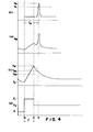
- Fig. 4 shows operation waveforms of the circuit shown in Fig. 3.
- the time ⁇ p varies depending on the input voltage values E1, E2 determining the temperature change conditions of the M transformation alloys M1, M2 and on the duration time ⁇ of the input voltage E1.
- a hard lock system may be constituted by permitting only a particular user to set a value on at least one of these four variables E1, E2, T and ⁇ p.
- Fig. 5 shows the principle of the code system in accordance with another embodiment of the present invention.
- an M transformation alloy M3 an input power source circuit 1 for supplying an input voltage to this M transformation alloy M3 and a current detection circuit 2 for detecting a current flowing through the M transformation alloy M3, are connected in a closed loop, for example.
- Fig. 6 shows still another embodiment of the code system of the present invention.
- the circuit shown in this figure is equipped with a closed loop circuit including an M transformation alloy M3, a power source 3 and a current detection circuit 2, an external heater 4 for heating or cooling the M transformation alloy M3 and an input power source circuit 5 for applying an input voltage E to the external heater 4.
- the power for the heating is applied in a predetermined interval by the input power source circuit 5 to the external heater 4, and the temperature of the M transformation alloy M3 is controlled as shown in Fig. 4(c), for example. Since the resistance value of the M transformation alloy M3 changes in the same way as the resistor R in Fig. 4(b), the arrival of the resistance value of the M transformation alloy M3 at the peak value can be detected by supervising the current that flows through the M transformation alloy M3 by the current detection circuit 2.
- the power source 3 consists of, for example, a constant voltage circuit that outputs a predetermined voltage.
- Fig. 7 is a schematic illustration of a hard lock system using the code system that contains the M transformation alloy element described above.
- the hard lock system shown in Fig. 7 includes an input power source circuit 7, an output detection circuit 8, a clock generation circuit 9 and a controller 10.
- an external heater 11 may be disposed in order to heat the M transformation alloy of the code system circuit 6.
- the controller 10 supplies a control signal to the input power source circuit 7, and the input voltage E is applied to the code system circuit 6 in accordance with the content of this control signal.
- the code system circuit 6 generates the peak voltage V after the passage of the predetermined time T p in response to the voltage value of the input voltage E and the duration time as described above, and the output detection circuit 8 detects the peak voltage.
- the controller 10 detects the time ⁇ p on the basis of the clock pulse supplied thereto from the clock generation circuit 9, outputs an output signal OUT as an enable signal when the time T p is within a predetermined error range with respect to a target value which is decided by the input voltage E and by the characteristics of the code system circuit 6, but does not output this enable signal when the time T p is not within the error range.
- the input signal IN to the controller 10 may be a secret number or other data supplied from a keyboard or card-reader, not shown in the drawing, and the controller 10 supplies the control signal that determines the voltage value of the input voltage E and the duration time, to the input power source circuit 7.
- the input voltage E having the predetermined voltage value and duration time is supplied to the code system circuit 6 on the basis of the secret number inputted by a customer and other data stored in a magnetic card or the like. If the time T p detected by the output detection circuit 8 in response to this input voltage E proves to be appropriate, the controller 10 outputs the enable signal and cash is dispensed by the cash dispenser.
- Fig. 8 shows still another embodiment of the invention wherein the M transformation alloy element is assembled in part of a card.
- the card body 12 in this case may be a mere support or a write-in board of readable character data 13. Furthermore, it may be an LSI board or IC card with a built-in IC circuit (with only a terminal 14 being shown in the drawing). Such a board or card may be used for making access to computer control of a production line or installation for which secrecy must be kept.
- small pieces 15a, 15b, 15c of the M transformation alloy are buried in three projections 16 which are buried or fitted and held at one of the ends of the card. Needless to say, one such projection will also do for the above purpose.
- the material for the card body 12 may be selected from any known materials such as plastics, ceramics, metals, wood, paper or their combinations depending on the kind of the M transformation alloy and the temperature range in which it is used.
- the heat transfer rate and the temperature rise rate will change with the materials or their combination selected, and hence the selection and combination of these materials is one of the parameters of the code system of the present invention.
- the materials so selected must have sufficient self-supporting properties within the temperature range in which the M transformation alloy operates. More particularly, the selected materials may be those that can be used within the temperature range (which is generally from minus several ten degrees to plus several hundred degrees C.) in which the M transformation alloy describes a hysteresis loop. Since the M transformation alloy describes the same hysteresis loop if it has the same temperature hysteresis, it is not always necessary to set the operation temperature at room temperature or so. In short, a suitable operation temperature range may be selected in consideration of the economy of usable cooling and heating media used and the operation accuracy of the M transformation alloy used.
- Fig. 9 is a schematic view of a system which makes a non-contact measurement of the temperature-resistance change of the M transformation alloy small piece 15 supported by the card of Fig. 8.
- cores 16 and 17 are disposed in such a manner as to interpose the M transformation alloy small piece 15 between them, and an AC is supplied to a coil 18 which is wound on the core 17, so that an eddy current occurs in the M transformation alloy small piece 15 to effect induction heating.
- Fig. 10 shows still another embodiment wherein the M transformation alloy elements 19a, 19b, 19c are disposed on an ID card 20 such as a bank cash card.
- an ID card 20 such as a bank cash card.
- a magnetic stripe 21 is also disposed in the card in order to establish interchangeability with a conventional magnetic card.
- Fig. 11 shows still another embodiment wherein the M transformation alloy elements 22a, 22b, 22c are disposed on a key 23.
- the M transformation alloy elements 22a, 22b, 22c are heated for a predetermined period of time by a heater disposed in the lock device, and the time T p from the start of heating till the outputting of the peak voltage, for example, is detected in the same manner as described above.
- This time T p is measured for each of the M transformation alloy elements 22a, 22b, 22c, and when the time is within a predetermined range, the lock is released.
- the present invention uses, as the code system, a material, such as the M transformation alloy, the change of electric resistance value of which describes a hysteresis loop with respect to the temperature change. Accordingly, the heating or cooling operation of the M transformation alloy is necessary for decoding, and unlike the conventional code relying upon softwares, the code of the present invention cannot be decoded at all by a trial-and-error method within a limited period of time. In other words, a long time is necessary to break the code of the present invention whereby is provided a code circuit which can practically not be decoded and can keep extremely reliably the secret information or data confidential.
- the code circuit of the present invention consists fundamentally of the resistor alone, it will not raise the problems that the coded data are destroyed by external static electricity or magnetism or an enable signal and the like are accidentally outputted.
- the present invention provides extremely highly reliable code circuits and hard lock systems.
Landscapes
- Physics & Mathematics (AREA)
- General Physics & Mathematics (AREA)
- Engineering & Computer Science (AREA)
- Computer Security & Cryptography (AREA)
- Lock And Its Accessories (AREA)
Applications Claiming Priority (2)
| Application Number | Priority Date | Filing Date | Title |
|---|---|---|---|
| JP189868/85 | 1985-08-30 | ||
| JP60189868A JPH0650424B2 (ja) | 1985-08-30 | 1985-08-30 | 暗号システムおよびそれに用いるハ−ドロツク用デバイス |
Publications (3)
| Publication Number | Publication Date |
|---|---|
| EP0213873A2 true EP0213873A2 (de) | 1987-03-11 |
| EP0213873A3 EP0213873A3 (en) | 1988-08-24 |
| EP0213873B1 EP0213873B1 (de) | 1992-12-23 |
Family
ID=16248513
Family Applications (1)
| Application Number | Title | Priority Date | Filing Date |
|---|---|---|---|
| EP86306396A Expired EP0213873B1 (de) | 1985-08-30 | 1986-08-19 | Codesystem für eine Schliesseinrichtung |
Country Status (4)
| Country | Link |
|---|---|
| US (1) | US4820910A (de) |
| EP (1) | EP0213873B1 (de) |
| JP (1) | JPH0650424B2 (de) |
| DE (1) | DE3687330T2 (de) |
Cited By (1)
| Publication number | Priority date | Publication date | Assignee | Title |
|---|---|---|---|---|
| US5655395A (en) * | 1993-06-04 | 1997-08-12 | Vendoret Holding S. A. | Card for a pledge lock |
Families Citing this family (8)
| Publication number | Priority date | Publication date | Assignee | Title |
|---|---|---|---|---|
| WO1990014626A1 (en) * | 1989-05-15 | 1990-11-29 | Dallas Semiconductor Corporation | Systems with data-token/one-wire-bus |
| US5157244A (en) * | 1989-12-19 | 1992-10-20 | Amp Incorporated | Smart key system |
| JPH0870694A (ja) * | 1994-09-02 | 1996-03-19 | Taniguchi Sangyo Kk | 移植用植物の苗床材 |
| US5637984A (en) * | 1994-10-20 | 1997-06-10 | Nanotechnology, Inc. | Pseudo-mechanical system incorporating ohmic electromechanical transducer and electrical generator |
| GB0118973D0 (en) * | 2001-08-03 | 2001-09-26 | Koninkl Philips Electronics Nv | Electronic key and reader apparatus for a lock |
| JP2006139330A (ja) * | 2004-11-10 | 2006-06-01 | Dainippon Printing Co Ltd | 非接触icカード、接触・非接触両用icカード |
| CN103867043B (zh) * | 2014-03-24 | 2016-05-04 | 佛山市川东磁电股份有限公司 | 一种安全防盗磁锁 |
| US9424722B2 (en) | 2014-05-14 | 2016-08-23 | Unlimited Liability, LLC | Smart memory material lock devices |
Family Cites Families (9)
| Publication number | Priority date | Publication date | Assignee | Title |
|---|---|---|---|---|
| US3237058A (en) * | 1960-08-25 | 1966-02-22 | Bell Telephone Labor Inc | Impedance measuring circuit |
| BE790492A (fr) * | 1971-10-27 | 1973-02-15 | Rca Corp | Systeme de surete electronique |
| US3900716A (en) * | 1972-10-17 | 1975-08-19 | Matsushita Electric Industrial Co Ltd | Optical static card reader |
| CH570010A5 (de) * | 1973-12-28 | 1975-11-28 | Grey Lab Establishment | |
| US3936662A (en) * | 1974-01-14 | 1976-02-03 | Anders Ruben Rausing | Interlocking system with a number of individual key elements |
| JPS576962Y2 (de) * | 1974-07-26 | 1982-02-09 | ||
| US4058705A (en) * | 1976-02-05 | 1977-11-15 | Cannon John W | Magnetic card reader |
| US4104515A (en) * | 1976-12-03 | 1978-08-01 | Xerox Corporation | Consumable credit card |
| SE425704B (sv) * | 1981-03-18 | 1982-10-25 | Loefberg Bo | Databerare |
-
1985
- 1985-08-30 JP JP60189868A patent/JPH0650424B2/ja not_active Expired - Lifetime
-
1986
- 1986-08-14 US US06/896,666 patent/US4820910A/en not_active Expired - Fee Related
- 1986-08-19 EP EP86306396A patent/EP0213873B1/de not_active Expired
- 1986-08-19 DE DE8686306396T patent/DE3687330T2/de not_active Expired - Fee Related
Cited By (1)
| Publication number | Priority date | Publication date | Assignee | Title |
|---|---|---|---|---|
| US5655395A (en) * | 1993-06-04 | 1997-08-12 | Vendoret Holding S. A. | Card for a pledge lock |
Also Published As
| Publication number | Publication date |
|---|---|
| EP0213873B1 (de) | 1992-12-23 |
| JPH0650424B2 (ja) | 1994-06-29 |
| JPS6250877A (ja) | 1987-03-05 |
| DE3687330D1 (de) | 1993-02-04 |
| US4820910A (en) | 1989-04-11 |
| DE3687330T2 (de) | 1993-07-22 |
| EP0213873A3 (en) | 1988-08-24 |
Similar Documents
| Publication | Publication Date | Title |
|---|---|---|
| EP0213873B1 (de) | Codesystem für eine Schliesseinrichtung | |
| DK0511140T3 (da) | System til udveksling af data mellem en elektronisk genstand, der koblet til en overførselsanordning, med forskellige datah | |
| GB2079017A (en) | Sensing record cards by electric induction | |
| EP0335904B1 (de) | Elektronische mehrphasen-temperatursteuervorrichtung | |
| JPS59145922A (ja) | 電子天びん | |
| US8177423B1 (en) | Thermal history sensor utilizing electrical conductivity and magnetic permeability | |
| US3054044A (en) | Temperature sensing circuit | |
| US4296315A (en) | Card reader security system | |
| EP1603075A1 (de) | Kapazitives datenspeicherungsverfahren, verschiedene systeme damit und verschiedene waren | |
| US20050088875A1 (en) | Sensor compensation for environmental variations for magnetic random access memory | |
| JPH07170001A (ja) | 磁気抵抗素子 | |
| US4373158A (en) | Device for altering encoded data | |
| JPS5823335A (ja) | 記録素子 | |
| JP3032832B2 (ja) | 情報記録媒体 | |
| JP2001274014A (ja) | 超電導コイル装置 | |
| JP2792669B2 (ja) | カード状記録媒体 | |
| JPS5798826A (en) | Temperature detecting element | |
| JPH0331359B2 (de) | ||
| JPH03247496A (ja) | 情報記憶装置および情報読取装置 | |
| JPH05229291A (ja) | メモリカードおよびメモリカード識別方式 | |
| Shoemaker et al. | A Probe for the Instantaneous Measurement of Surface Temperature | |
| GB2124812A (en) | Control means responsive to the presence of an article of a particular metal or alloy | |
| JPH08263834A (ja) | 磁気カード及びその記録再生装置 | |
| KR20040059011A (ko) | Rf 태그의 리셋회로 | |
| JPH02299893A (ja) | カード状記録媒体 |
Legal Events
| Date | Code | Title | Description |
|---|---|---|---|
| PUAI | Public reference made under article 153(3) epc to a published international application that has entered the european phase |
Free format text: ORIGINAL CODE: 0009012 |
|
| AK | Designated contracting states |
Kind code of ref document: A2 Designated state(s): DE FR GB IT |
|
| PUAL | Search report despatched |
Free format text: ORIGINAL CODE: 0009013 |
|
| AK | Designated contracting states |
Kind code of ref document: A3 Designated state(s): DE FR GB IT |
|
| 17P | Request for examination filed |
Effective date: 19890210 |
|
| 17Q | First examination report despatched |
Effective date: 19910320 |
|
| GRAA | (expected) grant |
Free format text: ORIGINAL CODE: 0009210 |
|
| ITF | It: translation for a ep patent filed | ||
| AK | Designated contracting states |
Kind code of ref document: B1 Designated state(s): DE FR GB IT |
|
| ET | Fr: translation filed | ||
| REF | Corresponds to: |
Ref document number: 3687330 Country of ref document: DE Date of ref document: 19930204 |
|
| PLBE | No opposition filed within time limit |
Free format text: ORIGINAL CODE: 0009261 |
|
| STAA | Information on the status of an ep patent application or granted ep patent |
Free format text: STATUS: NO OPPOSITION FILED WITHIN TIME LIMIT |
|
| 26N | No opposition filed | ||
| PGFP | Annual fee paid to national office [announced via postgrant information from national office to epo] |
Ref country code: GB Payment date: 19980810 Year of fee payment: 13 |
|
| PGFP | Annual fee paid to national office [announced via postgrant information from national office to epo] |
Ref country code: FR Payment date: 19980814 Year of fee payment: 13 |
|
| PGFP | Annual fee paid to national office [announced via postgrant information from national office to epo] |
Ref country code: DE Payment date: 19980831 Year of fee payment: 13 |
|
| PG25 | Lapsed in a contracting state [announced via postgrant information from national office to epo] |
Ref country code: GB Free format text: LAPSE BECAUSE OF NON-PAYMENT OF DUE FEES Effective date: 19990819 |
|
| GBPC | Gb: european patent ceased through non-payment of renewal fee |
Effective date: 19990819 |
|
| PG25 | Lapsed in a contracting state [announced via postgrant information from national office to epo] |
Ref country code: FR Free format text: LAPSE BECAUSE OF NON-PAYMENT OF DUE FEES Effective date: 20000428 |
|
| PG25 | Lapsed in a contracting state [announced via postgrant information from national office to epo] |
Ref country code: DE Free format text: LAPSE BECAUSE OF NON-PAYMENT OF DUE FEES Effective date: 20000601 |
|
| REG | Reference to a national code |
Ref country code: FR Ref legal event code: ST |
|
| PG25 | Lapsed in a contracting state [announced via postgrant information from national office to epo] |
Ref country code: IT Free format text: LAPSE BECAUSE OF NON-PAYMENT OF DUE FEES;WARNING: LAPSES OF ITALIAN PATENTS WITH EFFECTIVE DATE BEFORE 2007 MAY HAVE OCCURRED AT ANY TIME BEFORE 2007. THE CORRECT EFFECTIVE DATE MAY BE DIFFERENT FROM THE ONE RECORDED. Effective date: 20050819 |