EP0213922A2 - Dispositif de pulvérisation cathodique planaire à mouvement combiné circonférentiel et radial des champs magnétiques - Google Patents
Dispositif de pulvérisation cathodique planaire à mouvement combiné circonférentiel et radial des champs magnétiques Download PDFInfo
- Publication number
- EP0213922A2 EP0213922A2 EP86306587A EP86306587A EP0213922A2 EP 0213922 A2 EP0213922 A2 EP 0213922A2 EP 86306587 A EP86306587 A EP 86306587A EP 86306587 A EP86306587 A EP 86306587A EP 0213922 A2 EP0213922 A2 EP 0213922A2
- Authority
- EP
- European Patent Office
- Prior art keywords
- target
- magnetic
- axis
- assembly
- magnetic field
- Prior art date
- Legal status (The legal status is an assumption and is not a legal conclusion. Google has not performed a legal analysis and makes no representation as to the accuracy of the status listed.)
- Withdrawn
Links
- 238000001755 magnetron sputter deposition Methods 0.000 title claims abstract description 4
- 230000033001 locomotion Effects 0.000 title claims description 53
- 238000000576 coating method Methods 0.000 claims abstract description 24
- 239000011248 coating agent Substances 0.000 claims abstract description 23
- 238000004544 sputter deposition Methods 0.000 claims description 22
- 239000000463 material Substances 0.000 claims description 19
- 230000005684 electric field Effects 0.000 claims description 16
- 150000002500 ions Chemical class 0.000 claims description 7
- 239000002245 particle Substances 0.000 claims description 4
- 238000010408 sweeping Methods 0.000 claims description 2
- 239000013077 target material Substances 0.000 abstract description 13
- 230000003628 erosive effect Effects 0.000 description 8
- 235000012431 wafers Nutrition 0.000 description 8
- 238000000151 deposition Methods 0.000 description 7
- 230000008021 deposition Effects 0.000 description 6
- 238000005530 etching Methods 0.000 description 5
- 238000000034 method Methods 0.000 description 5
- 239000004065 semiconductor Substances 0.000 description 5
- XKRFYHLGVUSROY-UHFFFAOYSA-N Argon Chemical compound [Ar] XKRFYHLGVUSROY-UHFFFAOYSA-N 0.000 description 4
- 230000003252 repetitive effect Effects 0.000 description 4
- 238000005477 sputtering target Methods 0.000 description 3
- 206010044038 Tooth erosion Diseases 0.000 description 2
- XAGFODPZIPBFFR-UHFFFAOYSA-N aluminium Chemical compound [Al] XAGFODPZIPBFFR-UHFFFAOYSA-N 0.000 description 2
- 229910052782 aluminium Inorganic materials 0.000 description 2
- 229910052786 argon Inorganic materials 0.000 description 2
- 238000000429 assembly Methods 0.000 description 2
- 230000000712 assembly Effects 0.000 description 2
- 239000002826 coolant Substances 0.000 description 2
- 230000000694 effects Effects 0.000 description 2
- 239000007789 gas Substances 0.000 description 2
- 239000011261 inert gas Substances 0.000 description 2
- 239000007788 liquid Substances 0.000 description 2
- 238000004519 manufacturing process Methods 0.000 description 2
- 125000006850 spacer group Chemical group 0.000 description 2
- 230000000052 comparative effect Effects 0.000 description 1
- 238000001816 cooling Methods 0.000 description 1
- PCHJSUWPFVWCPO-UHFFFAOYSA-N gold Chemical compound [Au] PCHJSUWPFVWCPO-UHFFFAOYSA-N 0.000 description 1
- 239000010931 gold Substances 0.000 description 1
- 229910052737 gold Inorganic materials 0.000 description 1
- 238000010438 heat treatment Methods 0.000 description 1
- 239000012212 insulator Substances 0.000 description 1
- 230000003287 optical effect Effects 0.000 description 1
- 230000010355 oscillation Effects 0.000 description 1
- 238000000623 plasma-assisted chemical vapour deposition Methods 0.000 description 1
- 238000005086 pumping Methods 0.000 description 1
- 229910052710 silicon Inorganic materials 0.000 description 1
- 239000010703 silicon Substances 0.000 description 1
- 238000000992 sputter etching Methods 0.000 description 1
Images


Classifications
-
- H—ELECTRICITY
- H05—ELECTRIC TECHNIQUES NOT OTHERWISE PROVIDED FOR
- H05H—PLASMA TECHNIQUE; PRODUCTION OF ACCELERATED ELECTRICALLY-CHARGED PARTICLES OR OF NEUTRONS; PRODUCTION OR ACCELERATION OF NEUTRAL MOLECULAR OR ATOMIC BEAMS
- H05H1/00—Generating plasma; Handling plasma
-
- H—ELECTRICITY
- H01—ELECTRIC ELEMENTS
- H01J—ELECTRIC DISCHARGE TUBES OR DISCHARGE LAMPS
- H01J37/00—Discharge tubes with provision for introducing objects or material to be exposed to the discharge, e.g. for the purpose of examination or processing thereof
- H01J37/32—Gas-filled discharge tubes
- H01J37/34—Gas-filled discharge tubes operating with cathodic sputtering
- H01J37/3411—Constructional aspects of the reactor
- H01J37/345—Magnet arrangements in particular for cathodic sputtering apparatus
- H01J37/3455—Movable magnets
-
- H—ELECTRICITY
- H01—ELECTRIC ELEMENTS
- H01J—ELECTRIC DISCHARGE TUBES OR DISCHARGE LAMPS
- H01J37/00—Discharge tubes with provision for introducing objects or material to be exposed to the discharge, e.g. for the purpose of examination or processing thereof
- H01J37/32—Gas-filled discharge tubes
- H01J37/34—Gas-filled discharge tubes operating with cathodic sputtering
- H01J37/3402—Gas-filled discharge tubes operating with cathodic sputtering using supplementary magnetic fields
- H01J37/3405—Magnetron sputtering
- H01J37/3408—Planar magnetron sputtering
Definitions
- This invention relates to devices generating a plasma by establishing crossed electric and magnetic fields in a low pressure atmosphere of inert gas, for causing coating material to be removed from a target and deposited on an article to be coated; or for etching such an article. More particularly, this invention relates to devices of the foregoing type in which coatings are deposited (or material removed), specifically by sputtering, as in planar magnetron sputtering devices; plasma-assisted chemical vapor deposition; or by etching; and in which the magnetic field is moved during such coating or etching.
- the coating of articles by sputtering, as well as the related process of removal of surface material by etching, are well established arts. Both require establishing an environment in which ions bombard a surface from which material is sought to be removed; allowing the particles thus removed to condense on another surface which is to be coated.
- the ions result from a plasma created by establishing crossed magnetic and electrical fields in a low pressure atmosphere of inert gas, as for example within a processing or coating chamber.
- an article to be coated typically having an extended generally flat surface, is positioned within the processing chamber in spaced opposing relationship to a flat target material, which also preferably has an extended flat surface, and which is attached to one wall of the chamber but is insulated therefrom.
- the target is subjected to a DC or RF voltage, and acts as a cathode, while the walls of the chamber and the article to be coated may be at ground potential. An electric field is thus established in the space between the elements of the chamber at ground potential, and the cathode-target.
- a magnetic assembly establishes magnetic lines of force which pass through the target and, over a part of their path, are parallel with the surface thereof which is to be coated, as well as in crossed relationship to the electric field lines of force. Ions from the plasma bombard the target and erode material therefrom, and at least a part of the particles of material emanating from the target then accumulate on the surface of the article to be coated.
- an R F potential is applied to the article, while the target and other surrounding surfaces are at ground potential.
- the RF plasma then causes material to be eroded from the article, thus etching same.
- a characteristic of sputtering and other comparable processes is a tendency for the target material to he eroded nonuniformly, so that it must be replaced more frequently because of localized erosion, despite the fact that the remainder of the target may not exhibit much wear. If such a localized erosion can be minimized, and the target material utilized more uniformly, material and fabrication expenses can be greatly reduced.
- a principal application of sputter coating is to the processing of semiconductor wafers which are to be made into integrated circuits. Because of the extreme number of identical individual circuits, commonly called “chips", which are created from a single semiconductor wafer, of typically four to six inches in diameter, tolerances in the permissible variations in coating coverage along the surface area are extremely rigorous, and are becoming even more exacting as newer generation products, with even more densely packed active elements, are developed with time.
- the target is in the form of a flat disk, with the magnet assembly in the form of a smaller disk mounted off center to a drive shaft coinciding with the axis of the target disk.
- the target is a rectangular plate, with the magnet assembly being translated over a linear path back and forth to sweep the area of the target.
- an object of the invention is to provide a crossed field plasma discharge device for depositing a coating on an object with a hitherto unobtainable degree of uniformity; or to uniformly etch the surface of an article.
- the device comprises means for forming an electrical field, means for forming a magnetic field intersecting the electrical field, and magnetic field movement means for moving the magnetic field around the first axis at a first radial distance therefrom while causing the magnetic field to move radially with respect to the first axis during movement around the first axis.
- FIG. 1 A crossed field sputtering device in accordance with the present invention is illustrated in FIG. 1.
- a workpiece support 10 is positioned in a sputtering chamber 11 enclosed by a chamber housing 12 which can be evacuated by suitable vacuum pumping means (not shown) and can be backfilled with a suitable gas such as argon.
- suitable vacuum pumping means not shown
- a suitable gas such as argon.
- means for exchanging wafers automatically is also provided.
- a target assembly 16 comprising a sputtering target 18 and a target backing plate 20.
- the sputtering target 18 is fabricated of the material to be deposited on the workpiece 14 and is soldered to the target backing plate 20.
- Surrounding the workpiece support 10 and the workpiece 14 is an annular confinement shield 22 attached to a shield support 24, which is mounted to the chamber housing 12.
- the target backing plate 20 is provided with a flange 30 for mounting of the target assembly 16 to the chamber housing 12.
- the target assembly 16 and chamber housing 12 are electrically isolated by an insulator 32.
- an annular lower housing 36 and a generally plate-like upper housing 38 Mounted on the target assembly 16 external to the sputtering chamber 11 are an annular lower housing 36 and a generally plate-like upper housing 38.
- the target assembly 16, the lower housing 36, and the upper housing 38 enclose a chamber 40 which contains a magnet assembly 42.
- the device shown in Fig. 1 also includes means for establishing relative lateral motion between the magnet assembly 42 and the target 18.
- the magnet assembly 42 and the means for moving the magnet assembly 42 are described in detail hereinafter. It will be understood that the sputtering chamber 11 and the chamber 40 are isolated from each other. During operation of the sputtering device of Fig. 1, considerable heating of the target assembly 16 takes place.
- a liquid is typically circulated through the chamber 40 for heat removal.
- the liquid can be circulated through coolant hoses 44, 46 which pass through the upper housing 38 and connect to a cooling system (not shown).
- a workpiece 14 is introduced into the sputtering chamber 11 on the workpiece.support 10.
- the chamber 11 is sealed and evacuated.
- a background gas such as argon may be introduced.
- an electric field is established in the sputtering chamber 11 by application of a voltage between the target assembly 16 and the workpiece 14.
- the workpiece 14 is grounded (or maintained at a base DC or RF potential) and a DC or an RF voltage is applied to the target assembly 16. (Also chamber housing 12, shield 22, and shield support 24 are typically grounded).
- an electric field perpendicular to the target 18 and the workpiece 14 surfaces is established in the sputtering chamber 11.
- the magnet assembly 42 contains permanent magnets which establish magnetic fields, (illustrated by magnetic field line 48) as shown in FIG. 1, which have segments generally parallel to the target 18 surface and perpendicular to the electric field.
- a plasma is established in the sputtering chamber 11 in the region between the target 18 and the workpiece 14 where the electric and magnetic fields are crossed. Ions in the plasma bombard the target 18 surface and cause sputtering of the target material, some of which is deposited on the surface of the workpiece 14.
- one disadvantage of this arrangement is that a fixed point on the magnet assembly always rotates over a given radial position on the target, producing a given magnetic field strength and direction. At a different radial position on the target, a second magnetic field strength and direction is produced.
- the field strengths and directions at the different radial positions are not necessarily the same.
- the above disadvantages are overcome by providing a magnet assembly which is rotated about a central axis relative to the target surface and is simultaneously rotated about a second axis spaced from the central axis, the magnet assembly being mounted off-center with respect to the second axis.
- the magnet assembly is moved laterally in a plane parallel to the plane of the target on the side of the target opposite that which faces the workpiece.
- the magnet assembly is moved relative to the target in a predetermined pattern wherein substantially the entire area of the target is traversed.
- the pattern is essentially an epicycloid which is displaced about the axis of rotation with each successive revolution, the effect of which is a precession or rotation of the pattern about the central axis.
- the pattern traced by the magnet assembly can be predetermined by appropriate choice of the various gear ratios, rotation rates, diameters, etc. in order to achieve a given sputtered film uniformity and target erosion rate.
- FIG. 1-4 A preferred embodiment of the present invention for establishing lateral motion of the magnet assembly 42 is illustrated in FIG. 1-4.
- the means for moving the magnet assembly 42 includes a magnet rotor assembly 50, a rotor shaft assembly 52, a drive assembly 54, and a motor assembly 56. The entire assembly is shown in FIG. 1, while the magnet rotor assembly is illustrated in detail in FIGS. 2-4.
- the magnet rotor assembly 50 rotates about the rotor shaft assembly 52 when driven by the motor assembly 56 through the drive assembly 54.
- the rotor shaft assembly 52 includes a fixed shaft 60 rigidly attached at one end to an upwardly extending post 62 in the center of the target backing plate 20. The other end of the fixed shaft 60 is attached to the upper housing 38 by means of a center support flange 64.
- the rotor shaft assembly 52 also includes a fixed gear 66 and a gear spacer 68, both rigidly attached to the shaft 60 and concentric with the shaft 60 and positioned at the top of the hub post 62.
- the motor assembly 56 includes a motor 76 mounted to a motor bracket 78 which is fixedly attached to the upper housing 38.
- a motor mitre gear 80 is positioned on the drive shaft of the motor 76.
- the drive assembly 54 includes a drive shaft 84 positioned for rotation in bearings 86 carried in a drive hub 88 rigidly attached to the upper housing 38.
- a drive shaft mitre gear 90 is attached to one end of the drive shaft 84 and positioned to mesh with the motor mitre gear 80.
- a drive gear 92 is mounted at the opposite end of the drive shaft 84 and mates with a driven gear 94 on the rotor assembly 50.
- the rotor assembly 50 is caused to rotate at an angular velocity determined by the speed of the motor 76 and the gear ratios of the mitre gears 80, 90, the drive gear 92 and the driven gear 94.
- a cover 95 shields the operator from the mitre gears 80, 90, and the target voltage on shaft 84.
- a seal 201 prevents coolant from leaking out of chamber to around shaft 84.
- the rotor assembly 50 includes a rotor hub 96 which rotates about the fixed shaft 60 on bearings 98.
- the rotor assembly 50 is provided with idler shafts 100 which are symmetrically located on opposite sides of the rotor hub 96 with respect to the shaft 60 and which are mounted in bearings 102 so as to permit rotation with respect to the rotor hub 96.
- Attached to the idler shafts 100 are idler gears 104, each having teeth which mesh with the teeth of the fixed gear 66.
- the rotor assembly 50 is further provided with oscillator arms 106 attached to the ends of the rotor hub 96.
- the oscillator arms 106 are attached to the rotor hub 96 by means of mounting hardware 108 through slotted holes 110 for adjustability, to accommodate workpieces of different sizes and different target materials. Adjustment of the rotor hub 96 on the oscillator arm 106 determines the value R 1 in FIG. 6, whose significance will be discussed below. It will be understood that the oscillator arms 106 can be mounted in fixed positions or can simply be constructed as extensions of the rotor hub 70.
- oscillator shafts 120 Positioned near the end of the oscillator arms 104 are oscillator shafts 120 mounted with bearings 122 to permit rotation with respect to the idler gears 104. Mounted on the oscillator shafts 120 are oscillator gears 124, located for rotation by idler gears 104.
- the magnet assembly 42 is attached to one of the oscillator gears 124 through a spacer 126.
- the magnet assembly 42 is positioned off-center with respect to the oscillator shaft 120.
- Attached to the other oscillator gear 124 at the opposite end of the rotor hub 96 is a counterweight 128, having a similar size and weight to the magnet assembly 42.
- the purpose of the counterweight 128 is to provide balanced rotation of the rotor assembly 50.
- a second magnet assembly can be connected to the opposite end of the rotor assembly 50.
- the magnet rotor assembly 50 is also provided with a magnet support arm 130, mounted to the central portion of the rotor hub 96, and angularly displaced from the idler gear 104 and oscillator arm 106, as shown in FIGS. 2 and 3. Attached near the ends of the magnet support arm 130 are permanent magnets 132 used for rotation sensing. A rotation sensor 134 is mounted in the upper housing 38 in alignment with the permanent magnets 132. Each time a magnet 132 passes the rotation sensor 134, a rotation indicating signal is generated for use by associated control apparatus (not shown). It will be understood that any convenient type of rotation sensing device, such as optical or capacitive, can also be utilized.
- the magnet assembly 42 is shown in more detail in FIGS. 4 and 5.
- Permanent magnets 140 are mounted in a circular cup-shaped holder 142.
- the magnets 140 are each mounted with the north-south axis aligned with a radius of the cup-shaped holder 142, such that north poles of each magnet 140 are adjacent the center of the holder 142 and south poles are adjacent the periphery.
- Other magnet configurations can be utilized, as shown in US-A-44446 4 3. However, generally the permanent magnets are mounted on radii of a circle.
- Operation of the motor 76 causes rotation of the drive shaft 84 and the drive gear 92.
- the driven gear 94 and attached rotor hub 96 are caused to rotate about the fixed shaft 60 (also defining the central axis of target 18).
- FIG. 3 it can be seen that as the rotor hub 96 rotates about the shaft 60, the idler gears 104 rotate because the gear 66 is fixed in relation to the shaft 60 and does not rotate. Rotation of the idler gears 104 in turn causes rotation of the oscillator gears 124 and the attached magnet assembly 42.
- the magnet assembly 42 is mounted eccentrically with respect to the oscillator shaft 120 by a distance R2, as illustrated and explained in detail in connection with FIG. 6. In operation, the entire rotor assembly 50 carried by the rotor hub 96 rotates about the shaft 60 and the magnet assembly 42 simultaneously rotates around the oscillator shaft 120.
- the resultant motion depends in detail on the parameters of the rotor assembly, such as gear ratios and radii.
- the magnet assembly 42 moves laterally in a plane parallel to the target 18 in a generally circular fashion.
- the motion of the magnet assembly 42 which results in more uniform coverage of the target can be broken down into a circumferential component and a radial component 18, i.e., or into circular movement about the central axis of target 18, plus radial movement with respect to the central axis; or into two circular components, as mentioned above.
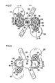
- a single rotation of the magnet assembly 42 about the central axis 60 of the target 18, including the combination of both circumferential and radial motion, is illustrated generally in FIG. 7.
- the resultant motion defines an eccentric path 45 of the magnet assembly 42 over target 18.
- a magnet assembly path 45 such as shown in FIG. 7 can be designed by proper choice of the gear ratio to rotate about the central axis 60.
- the path 42 precesses, moving over some new areas of target 18, while overlapping other previously-swept areas of target at successively different angles of attack, sweeping out a cycloidal pattern over time, and resulting in uniform tracing of the target area during successive rotations.
- the magnet assembly 42 is successively moved over substantially the entire surface area of the target 18.
- the magnet assembly and its magnetic field are placed in different orientations with respect to each point on the target surface.
- sputtering occurs from essentially the entire target surface, and material is deposited on the workpiece from a variety of directions due to the various field orientations. Uniform erosion of the target 18 and uniform deposition of the target material on the workpiece 14 are thereby promoted.
- the resultant eccentric motion of the magnet assembly 42 about central axis 60 can also be analyzed into combinations or various other simultaneous motions, for example, of one larger diameter circular motion at a first radial distance R 1 about central axis 60, and a second circular motion about a smaller radial distance R 2 , and centered on a circular locus at a distance R 1 from the central axis.
- FIG. 6 best illustrates this analysis of the motion of assembly 42.
- illustrated in outline form are fixed gear 66, whose axis coincides with central axis 60; idler gears 104; oscillator gears 124; and magnetic assembly 42 mounted to one of oscillator gears 124; and counterweight 128 mounted similarly to the other of the oscillator gears.
- magnet assembly 42 is mounted off center with respect to the central axis and shaft of oscillator gear 124. This offset distance between the respective centers of assembly 42, and the oscillator gear is of course the smaller radial distance R 2 in FIG. 6.
- a resultant radius R will be defined, extending between central axis 60 and the center of magnet assembly 42; this resultant radius can be seen to be the third leg of a triangle whose smaller first legs are R1 and R2, and which subtend therebetween the angle theta.
- This radius R is of course the radius of the locus of the center of the magnet assembly 42 as it moves about the central axis 60, in a movement resulting from the combination of the larger circular motion at radius R 1 and the smaller circular offset motion of radius R 2 .
- One example of such a locus or path 45 of the center of assembly 42 is that of FIG. 7.
- the path is generally egg-shaped, or more properly cycloidal, since it is not retraced in each successive revolution around axis 60. Rather, path 45 precesses, to a degree controlled by the choice of gear ratios and relative rotation speeds, so that a new area of the target is included during each successive sweep, while previously swept points on the target are again swept, but at angles differing from those of the previous sweeps.
- the particular path traced by the magnet assembly 42 depends on the radii and gear ratios of the rotor assembly 50. Since the magnet assembly 42 is a rigid unit, consideration of the motion of one point thereon is representative of the motion of the assembly.
- One further helpful way of analyzing the manner in which the pattern such as that of FIG. 7 traced is by comparison of the rate of rotation Wr of the rotor hub 96 and the rate of oscillation W0 of the magnet assembly 42 about the oscillator shaft 120. Simplified examples for purposes of this analysis of possible magnet paths are given in FIGS. 8 and 9. FIG.
- the dashed circles in FIG. 8 represent the inner and outer limits of motion of the point M on the magnet assembly 42.
- the pattern shown in FIG. 8 is repetitive since it begins and ends at point A.
- the pattern shown in FIG. 9 is repetitive since it starts and ends at point B.
- Repetitive patterns are undesirable in obtaining uniform target erosion and uniform film deposition since they repetitively trace the same patterns and will cause a pattern of non-uniform erosion grooves in the target.
- Such repetitive patterns are avoided in the present invention by causing the patterns to rotate about the axis 60 by proper selection of the gear ratios in the rotor assembly 50.
- the pattern can be made to rotate about the axis 60 by establishing gear ratios wherein WO is slightly greater or slightly less than Wr. The pattern then begins at point A but ends at point A' or A".
- the second rotation about the axis 60 starts at A' or A" and is displaced from the first.
- successive rotations will be displaced around the target area.
- WO is slightly greater or slightly less than 4Wr
- the pattern shown in FIG. 9 is displaced during each successive rotation. In this manner it may be seen that a pattern such as that of FIG. 7 is produced which does not repeat itself on each successive rotation, but rather constantly includes new areas, while changing its orientation with respect to the previous sweep path when overlapping previously swept areas.
- the patterns shown in FIGS. 7, 8 and 9 are but examples of a large number of patterns which can be employed in accordance with the present invention.
- WO is made unequal to nWr where n is an integer.
- the spacing between successive patterns can also be determined by the relative values of WO and Wr.
- a further consideration in selecting the pattern to be traced is that the entire target surface should be traversed by the magnet assembly one or more complete times during the deposition time of a workpiece in order to insure uniform film deposition.
- the pattern of magnet coverage during deposition can be adjusted to some extent by varying the speed of rotation of the magnet assembly about the central axis 60.
- a further consideration is that the inner and outer radial limits of magnet assembly travel, as determined by the size and eccentric mounting position of the magnet assembly, and the adjustment of rotor hub 96 on oscillator arm 106, should correspond generally with the target dimensions, object dimension and target material.
- An inventive system in accordance with the above has achieved, on a 150 millimeter wafer, a uniformity of coating of at least + 4.5% (excluding the outer few millimeters of the workpiece radius). Moreover, each given location on the workpiece has received deposited material from so many different angles due to the many variations in the position of magnetic field to which the location has been exposed during successive rotations of magnet assembly 42. Thus coating coverage in the main plane of a flat workpiece not only has superior uniformity, but also any irregularities or steps in the workpiece also will be coated much more uniformly than in the prior art.
Landscapes
- Physics & Mathematics (AREA)
- Engineering & Computer Science (AREA)
- Plasma & Fusion (AREA)
- Chemical & Material Sciences (AREA)
- Analytical Chemistry (AREA)
- Spectroscopy & Molecular Physics (AREA)
- Physical Vapour Deposition (AREA)
- Physical Deposition Of Substances That Are Components Of Semiconductor Devices (AREA)
- ing And Chemical Polishing (AREA)
- Electrodes Of Semiconductors (AREA)
Applications Claiming Priority (2)
| Application Number | Priority Date | Filing Date | Title |
|---|---|---|---|
| US76923285A | 1985-08-26 | 1985-08-26 | |
| US769232 | 1985-08-26 |
Publications (2)
| Publication Number | Publication Date |
|---|---|
| EP0213922A2 true EP0213922A2 (fr) | 1987-03-11 |
| EP0213922A3 EP0213922A3 (fr) | 1988-09-07 |
Family
ID=25084868
Family Applications (1)
| Application Number | Title | Priority Date | Filing Date |
|---|---|---|---|
| EP86306587A Withdrawn EP0213922A3 (fr) | 1985-08-26 | 1986-08-26 | Dispositif de pulvérisation cathodique planaire à mouvement combiné circonférentiel et radial des champs magnétiques |
Country Status (3)
| Country | Link |
|---|---|
| EP (1) | EP0213922A3 (fr) |
| JP (1) | JPS6247478A (fr) |
| KR (1) | KR870002748A (fr) |
Cited By (13)
| Publication number | Priority date | Publication date | Assignee | Title |
|---|---|---|---|---|
| EP0211412A3 (en) * | 1985-08-02 | 1988-09-14 | Fujitsu Limited | Planar magnetron sputtering apparatus and its magnetic source |
| EP0283095A1 (fr) * | 1987-03-16 | 1988-09-21 | Hauzer Holding B.V. | Méthode et dispositif pour déplacer mécaniquement un dispositif de génération de champ magnétique dans un dispositif d'évaporation par décharge par arc de cathode |
| WO1990013137A1 (fr) * | 1989-04-27 | 1990-11-01 | Ionic Coatings Limited | Appareil de pulverisation |
| EP0492992A3 (en) * | 1990-12-21 | 1992-08-05 | Novellus Systems, Inc. | Magnetron sputtering equipment |
| EP0503138A1 (fr) * | 1991-03-08 | 1992-09-16 | Leybold Aktiengesellschaft | Dispositif pour actionner un appareil à aimants d'un magnétron planar pour une installation de pulvérisation cathodique |
| DE4426200A1 (de) * | 1994-07-23 | 1996-01-25 | Leybold Ag | Kathodenzerstäubungsvorrichtung |
| EP0918351A1 (fr) * | 1997-11-19 | 1999-05-26 | Sinvaco N.V. | Magnétron planaire à ensemble d'aimants déplaçable |
| US6258217B1 (en) | 1999-09-29 | 2001-07-10 | Plasma-Therm, Inc. | Rotating magnet array and sputter source |
| GB2413702A (en) * | 2004-04-27 | 2005-11-02 | Trikon Technologies Ltd | Methods and apparatus for controlling rotating magnetic fields |
| EP2090673A1 (fr) * | 2008-01-16 | 2009-08-19 | Applied Materials, Inc. | Dispositif de revêtement par pulvérisation |
| CN108624856A (zh) * | 2018-07-05 | 2018-10-09 | 包头稀土研究院 | 靶材组件 |
| CN114545487A (zh) * | 2022-01-14 | 2022-05-27 | 中国原子能科学研究院 | 一种旋转靶装置 |
| CN120967312A (zh) * | 2025-10-22 | 2025-11-18 | 无锡尚积半导体科技股份有限公司 | 磁控溅射设备用多自由度复合运动磁控装置 |
Families Citing this family (4)
| Publication number | Priority date | Publication date | Assignee | Title |
|---|---|---|---|---|
| US5188717A (en) * | 1991-09-12 | 1993-02-23 | Novellus Systems, Inc. | Sweeping method and magnet track apparatus for magnetron sputtering |
| WO2006085354A1 (fr) * | 2005-02-08 | 2006-08-17 | Tohoku Seiki Industries, Ltd. | Systeme de pulverisation |
| JP6265534B2 (ja) * | 2014-03-04 | 2018-01-24 | 株式会社アルバック | スパッタリングカソード |
| JP2023049164A (ja) * | 2021-09-29 | 2023-04-10 | 株式会社アルバック | マグネトロンスパッタリング装置用のカソードユニット及びマグネトロンスパッタリング装置 |
Family Cites Families (4)
| Publication number | Priority date | Publication date | Assignee | Title |
|---|---|---|---|---|
| DE2707144A1 (de) * | 1976-02-19 | 1977-08-25 | Sloan Technology Corp | Kathodenzerstaeubungsvorrichtung |
| GB2125440A (en) * | 1982-07-13 | 1984-03-07 | Christopher Elphick | Tunnel magnetron for cathode sputtering |
| US4444643A (en) * | 1982-09-03 | 1984-04-24 | Gartek Systems, Inc. | Planar magnetron sputtering device |
| JPS6260866A (ja) * | 1985-08-02 | 1987-03-17 | Fujitsu Ltd | マグネトロンスパツタ装置 |
-
1986
- 1986-08-25 JP JP61197467A patent/JPS6247478A/ja active Pending
- 1986-08-26 EP EP86306587A patent/EP0213922A3/fr not_active Withdrawn
- 1986-08-26 KR KR1019860007064A patent/KR870002748A/ko not_active Withdrawn
Cited By (18)
| Publication number | Priority date | Publication date | Assignee | Title |
|---|---|---|---|---|
| EP0211412A3 (en) * | 1985-08-02 | 1988-09-14 | Fujitsu Limited | Planar magnetron sputtering apparatus and its magnetic source |
| US4872964A (en) * | 1985-08-02 | 1989-10-10 | Fujitsu Limited | Planar magnetron sputtering apparatus and its magnetic source |
| EP0283095A1 (fr) * | 1987-03-16 | 1988-09-21 | Hauzer Holding B.V. | Méthode et dispositif pour déplacer mécaniquement un dispositif de génération de champ magnétique dans un dispositif d'évaporation par décharge par arc de cathode |
| WO1990013137A1 (fr) * | 1989-04-27 | 1990-11-01 | Ionic Coatings Limited | Appareil de pulverisation |
| EP0492992A3 (en) * | 1990-12-21 | 1992-08-05 | Novellus Systems, Inc. | Magnetron sputtering equipment |
| US5171415A (en) * | 1990-12-21 | 1992-12-15 | Novellus Systems, Inc. | Cooling method and apparatus for magnetron sputtering |
| EP0503138A1 (fr) * | 1991-03-08 | 1992-09-16 | Leybold Aktiengesellschaft | Dispositif pour actionner un appareil à aimants d'un magnétron planar pour une installation de pulvérisation cathodique |
| DE4426200A1 (de) * | 1994-07-23 | 1996-01-25 | Leybold Ag | Kathodenzerstäubungsvorrichtung |
| EP0918351A1 (fr) * | 1997-11-19 | 1999-05-26 | Sinvaco N.V. | Magnétron planaire à ensemble d'aimants déplaçable |
| WO1999026274A1 (fr) * | 1997-11-19 | 1999-05-27 | Sinvaco N.V. | Magnetron plan ameliore a ensemble aimants mobile |
| US6322679B1 (en) | 1997-11-19 | 2001-11-27 | Sinvaco N.V. | Planar magnetron with moving magnet assembly |
| US6258217B1 (en) | 1999-09-29 | 2001-07-10 | Plasma-Therm, Inc. | Rotating magnet array and sputter source |
| GB2413702A (en) * | 2004-04-27 | 2005-11-02 | Trikon Technologies Ltd | Methods and apparatus for controlling rotating magnetic fields |
| GB2413702B (en) * | 2004-04-27 | 2008-08-20 | Trikon Technologies Ltd | Methods and apparatus for controlling rotating magnetic fields |
| EP2090673A1 (fr) * | 2008-01-16 | 2009-08-19 | Applied Materials, Inc. | Dispositif de revêtement par pulvérisation |
| CN108624856A (zh) * | 2018-07-05 | 2018-10-09 | 包头稀土研究院 | 靶材组件 |
| CN114545487A (zh) * | 2022-01-14 | 2022-05-27 | 中国原子能科学研究院 | 一种旋转靶装置 |
| CN120967312A (zh) * | 2025-10-22 | 2025-11-18 | 无锡尚积半导体科技股份有限公司 | 磁控溅射设备用多自由度复合运动磁控装置 |
Also Published As
| Publication number | Publication date |
|---|---|
| KR870002748A (ko) | 1987-04-06 |
| JPS6247478A (ja) | 1987-03-02 |
| EP0213922A3 (fr) | 1988-09-07 |
Similar Documents
| Publication | Publication Date | Title |
|---|---|---|
| US4714536A (en) | Planar magnetron sputtering device with combined circumferential and radial movement of magnetic fields | |
| EP0213922A2 (fr) | Dispositif de pulvérisation cathodique planaire à mouvement combiné circonférentiel et radial des champs magnétiques | |
| US4444643A (en) | Planar magnetron sputtering device | |
| US11236415B2 (en) | Deposition system with shield mount | |
| US4552639A (en) | Magnetron sputter etching system | |
| US5833815A (en) | Sputter deposition system | |
| EP0884761B1 (fr) | Appareil de pulverisation à magnetronavec un ensemble rotatif d'aimants | |
| US4025410A (en) | Sputtering apparatus and methods using a magnetic field | |
| JP4306958B2 (ja) | 真空スパッタ装置 | |
| US5126029A (en) | Apparatus and method for achieving via step coverage symmetry | |
| JP4213777B2 (ja) | スパッタリング装置及び方法 | |
| GB2310433A (en) | Cathode sputtering | |
| KR0178555B1 (ko) | 회전 마그네트 캐소드를 갖는 마그네트론 스퍼터 코팅 장치 및 그 방법 | |
| WO1990013137A1 (fr) | Appareil de pulverisation | |
| US4906347A (en) | Dry-etching apparatus | |
| EP0801416A1 (fr) | Chambre de traitement à plasma avec assemblage epicyclique d'aimants | |
| JP3056222B2 (ja) | スパッタ装置およびスパッタ方法 | |
| JPH0350832B2 (fr) | ||
| JP4274452B2 (ja) | スパッタ源及び成膜装置 | |
| JPH11340165A (ja) | スパッタリング装置及びマグネトロンユニット | |
| EP0169680A1 (fr) | Dispositif de gravure par pulvérisation au moyen d'un magnétron | |
| JPS5918638A (ja) | ドライエツチング装置 | |
| JPH04371575A (ja) | スパッタ装置 | |
| JPH11140639A (ja) | マグネトロン装置及びスパッタリング装置 | |
| JPH11217669A (ja) | マグネトロン装置及びスパッタリング装置 |
Legal Events
| Date | Code | Title | Description |
|---|---|---|---|
| PUAI | Public reference made under article 153(3) epc to a published international application that has entered the european phase |
Free format text: ORIGINAL CODE: 0009012 |
|
| 17P | Request for examination filed |
Effective date: 19861031 |
|
| AK | Designated contracting states |
Kind code of ref document: A2 Designated state(s): DE FR GB |
|
| PUAL | Search report despatched |
Free format text: ORIGINAL CODE: 0009013 |
|
| AK | Designated contracting states |
Kind code of ref document: A3 Designated state(s): DE FR GB |
|
| 17Q | First examination report despatched |
Effective date: 19900103 |
|
| STAA | Information on the status of an ep patent application or granted ep patent |
Free format text: STATUS: THE APPLICATION IS DEEMED TO BE WITHDRAWN |
|
| 18D | Application deemed to be withdrawn |
Effective date: 19920116 |
|
| RIN1 | Information on inventor provided before grant (corrected) |
Inventor name: LEI, LAWRENCE C. Inventor name: HARRA, DAVID J. Inventor name: FREEMAN, KENNETH Inventor name: GARRETT, CHARLES B. |