EP0213929B1 - Méthode et appareil de commande pour un système de radio-téléphone - Google Patents
Méthode et appareil de commande pour un système de radio-téléphone Download PDFInfo
- Publication number
- EP0213929B1 EP0213929B1 EP86306617A EP86306617A EP0213929B1 EP 0213929 B1 EP0213929 B1 EP 0213929B1 EP 86306617 A EP86306617 A EP 86306617A EP 86306617 A EP86306617 A EP 86306617A EP 0213929 B1 EP0213929 B1 EP 0213929B1
- Authority
- EP
- European Patent Office
- Prior art keywords
- signal
- radio telephone
- channel
- master apparatus
- radio
- Prior art date
- Legal status (The legal status is an assumption and is not a legal conclusion. Google has not performed a legal analysis and makes no representation as to the accuracy of the status listed.)
- Expired - Lifetime
Links
Images



Classifications
-
- H—ELECTRICITY
- H04—ELECTRIC COMMUNICATION TECHNIQUE
- H04M—TELEPHONIC COMMUNICATION
- H04M1/00—Substation equipment, e.g. for use by subscribers
- H04M1/72—Mobile telephones; Cordless telephones, i.e. devices for establishing wireless links to base stations without route selection
- H04M1/725—Cordless telephones
- H04M1/72502—Cordless telephones with one base station connected to a single line
- H04M1/72505—Radio link set-up procedures
- H04M1/72508—Radio link set-up procedures using a control channel
Definitions
- This invention relates to a radio telephone system control apparatus and a method for controlling the connection of a master apparatus connected to a wired telephone channel and a plurality of radio telephone sets connected to the master apparatus through radio channels with the master apparatus, and more particularly an apparatus for controlling the connection in response to a paging made through lines for wired telephone sets.
- US-A-3906166 shows a cellular telephone system in which a base station transmits a paging signal to a specific radio telephone set in order to open communication with that set.
- the set replies by transmitting direct to the base station or to a receiver site connected to the base station.
- the radio telephone set is tuned automatically to the frequency of the nearest satellite receiver.
- radio telephone systems comprising a master apparatus connected to wired telephone channels and one or more radio telephone sets connected to the master apparatus through radio channels may be mentioned a so-called cordless telephone apparatus, for example.
- the cordless telephone apparatus is constituted by a master apparatus connecting apparatus connected to wired telephone channels, and a wireless telephone set provided for the master apparatus in a one to one correspondence, and the frequencies of its signals are fixed such that up radio channels from the radio telephone sets to the master apparatus utilise signals of frequency f1, while down telephone channels from the master apparatus to the radio telephone sets utilise signals of frequency f2.
- a so-called multi-channel access system wherein a frequency being used is determined by utilising a common channel, for example, a control channel between a plurality of master apparatus, and then the channel is switched to a speech channel corresponding to the frequency.
- a common channel for example, a control channel between a plurality of master apparatus
- the two master apparatus start connection control using respective control channels simultaneously, whereby radio waves from these control channels interfere with each other.
- the connection control is sometime made impossible.
- radio telephone system control apparatus comprising: a plurality of radio telephone sets, each having a transceiver; a master apparatus connected to a wired telephone channel and having a transceiver for exchanging signals between the master apparatus and the transceiver of each of said telephone sets; means provided in said master apparatus for detecting a ring signal on said wired telephone channel; means for sequentially sending, with a predetermined time delay, paging signals each containing a channel designating signal to the transceiver of each of said plurality of radio telephone sets from the transceiver of said master apparatus when said ring signal is detected on said wired telephone channel; means provided in each of said plurality of radio telephone sets responsive to the paging signal containing a channel designating signal received from the master apparatus for sending a paging response signal to the master apparatus transceiver, and for switching the radio channel of the transceiver of each of said radio telephone sets to a radio channel corresponding to said channel designating signal; means in said master apparatus transceiver
- the invention provides a methods of controlling a radio telephone system, as set forth in the accompanying independent claim 22.
- a preferred embodiment of the radio telephone system according to this invention shown in Fig.1 comprises one master apparatus 4 and two radio telephone sets 5 and 5′. For the purpose of simplifying the description, only two radio telephone sets are shown but it will be clear that the invention is also applicable to three or more radio telephone sets.
- the master apparatus 4 is connected to a wired telephone channel, not shown, through a terminal 3.
- a signal from the wired telephone channel inputted to terminal 3 is supplied to a transmitter 16 via a line relay 23 and a hybrid circuit 22, while the output from the transmitter 16 is sent out from an antenna 12 via an antenna duplexer 13.
- a signal received by antenna 12 is applied to a receiver 14 through antenna duplexer 13, and the output from the receiver 14 is supplied to the wired telephone channel via hybrid circuit 22, line relay 23 and terminal 3.
- a synthesizer 21 is provided for determining the radio frequency of the transmitter 16 and the receiver 14, and a control unit 15 is provided for the purpose of controlling transmitter 16, receiver 14 and synthesizer 21.
- Read only memory devices (ROM) 18 and 18′ are provided for the purpose of storing identification information for controlling the connections to radio telephone sets to be described later, the identification information being used in the control unit 15.
- the radio telephone sets 5 and 5′ are connected to the master apparatus through wireless channels.
- the wireless telephone sets 5 and 5′ have the same construction except that their ROMs 17 and 17′ store different information. More particularly, element 6 bounded by dotted lines in Fig.1 has the same construction for both telephone sets 5 and 5′ so that in the following description, elements utilized in radio telephone set 5′ are designated by the same reference numberals as those used in the radio telephone set 5 except addition of a prime.
- the signal transmitted from the master apparatus is received by an antenna 11 and applied to a receiver 19 through an antenna duplexer 10, and the output of the receiver 19 is supplied to a handset or loudspeaker 29 to be connected to generate sound.
- a signal inputted to a microphone 30 is sent to the master apparatus 4 via transmitter 8, antenna duplexer 10, and antenna 11.
- a synthesizer 20 is provided for determining the radio frequency of receiver 19 and transmitter 8, while a control unit 9 is provided for controlling receiver 19, transmitter 8 and synthesizer 20.
- a loudspeaker 31 connected to the synthesizer produces a call tone.
- a hook switch 7 is provided to effect an origination and to respond to the call tone produced by the loudspeaker 31.
- ROMs 17 and 17′ corresponds to that stored in ROMs 18 and 18′ of the master apparatus 4.
- This embodiment employs a multichannel access system comprising a single control channel (C-CH) and a plurality, for example 45, of speech channels.
- C-CH control channel
- a speech channel is established by commonly utilizing a single control channel by a plurality of apparatus. The operation of this embodiment will be described with reference to the flow charts shown in Figs. 2 through 6.
- Fig. 2 shows a flow chart for the case when an origination is issued from radio telephone set 5.
- step 201 when the hook switch 7 of the radio telephone set 5 is hooked off at step 202, this state change is detected by control unit 9 and this unit 9 turns ON the transmitter 8, and then at step 203 the originating signal is sent to the master apparatus 4 via antenna duplexer 10 and antenna 11.
- the transmission of the originating signal from the radio telephone set 5 to the master apparatus 4 is made by using the control channel (C-CH).
- the control unit 9 turns off the transmitter 8.
- the master apparatus 4 receives with receiver 14 the originating signal via antenna 12 and antenna duplexer 13 and the demodulated output from the receiver 14 is applied to the control unit 15.
- the control unit 15 turns ON transmitter 16 for transmitting a call signal to radio telephone set 5′ at step 207.
- the transmission of the call signal from the master apparatus 4 to the radio telephone set 5′ is performed by using the control channel (C-CH).
- C-CH control channel
- an identifying information is incorporated into the call signal stored in the ROM 18′.
- the radio telephone set 5′ receives the call signal, it compares the identifying signal contained in the call signal with the information stored in ROM 17′, and when they coincide with each other, the radio telephone set 5′ accepts the call signal.
- a digit '2' shows a signal containing the identifying signal stored in ROM 18′
- a digit '1' shows a signal containing an identifying signal stored in ROM 18.
- An identifying signal stored in ROMs 18, 18′, 17 and 17′ is made up of a identifying code common to both radio telephone sets 5 and 5′ and individual identifying codes assigned to respective radio telephone sets 5 and 5′. The common identifying code is used to identify the other radio telephone set.
- the radio telephone set 5′ receives a call signal 2 transmitted from the master apparatus 4 by receiver 19′ through antenna 11′ and antenna duplexer 10′.
- the demodulated output from receiver 19′ is supplied to control unit 9′ whereby it turns ON transmitter 8′ at step 209, and a call response signal 2 is sent to the master apparatus 4 at step 210.
- the call response signal 2 contains an identifying signal stored in ROM 17′.
- the control unit 9′ of the radio telephone system 5′ turns OFF transmitter 8′.
- step 212 the master apparatus 4 executes a judgment as to whether a predetermined time has elapsed or not.
- the program is transferred to step 213 at which a judgment is made as to whether receiver 14 has received a call response signal 2 from radio telephone set 5′ or not.
- the program is returned to step 312.
- result of judgment at step 212 shows a time out and when the result of judgment at step 213 shows a receival of a call response signal 2
- the program is transferred to step 214. More particularly, when a predetermined time has elapsed after sending out a call signal 2 from the master apparatus 4, or when a call response signal 2 is received from radio telephone set 5′, the program is transferred to step 214.
- a channel designating signal 1 for designating a predetermined channel is transmitted to radio telephone set 5 by using the control channel.
- the radio telephone set 5 executes a judgment as to whether the radio telephone set 5 has received the channel designating signal 1 or not.
- the control unit 9 controls the synthesizer 20 for switching the radio frequency of transmitter 8 and receiver 19 to that corresponding to a predetermined speech channel (S-CH1) at step 216.
- S-CH1 predetermined speech channel
- the master apparatus 4 sends out a channel designating signal 2 to radio telephone set 5′ by using the control channel.
- the channel designating signal 2 designates the same speech channel as the channel designating signal 1.
- the master apparatus 4 turns OFF transmitter 16 so as to control the synthesizer 21, thereby switching the transmission/reception frequency to that corresponding to speech channel (S-CH1) and then turning ON transmitter 16 at step 222.
- speech between the master apparatus and the radio telephone set 5 becomes possible by utilizing the speech channel (S-CH1).
- step 223 in radio telephone set 5′ a judgment is made as to whether the channel designating signal 2 sent from the master apparatus 4 has been received or not.
- the program is advanced to step 224 at which the transmission/reception frequency is switched to that corresponding to speech channel (S-CH1) and at step 235, the state is changed to a waiting state. Under this state since the transmitter 8′ at the radio telephone set 5′ is OFF, the radio telephone set 5′ can receive only a signal from the master apparatus 4 utilizing speech channel (S-CH1).
- the radio telephone set 5 After turning ON the receiver 8 at step 218, the radio telephone set 5 turns ON the audio frequency circuit of the transmitter 8 and receiver 19 at step 226.
- the master apparatus turns ON transmitter 16 and turns ON line relay 23 at step 227 for closing a relay contact, whereby radio telephone set 5 can make speech through a wired telephone channel connected to terminal 3 of the master apparatus 4 by using a handset 29 and microphone 30.
- the hook switch 7′ of the radio telephone set 5′ now in the waiting state is hooked OFF, the reception of the speech is possible but transmission thereof is impossible.
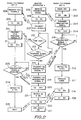
- Fig. 3 shows a flow chart showing the operation of a case in which the paging is made to the master apparatus from a wired telephone channel.
- the detection of the paging is made by judging the presence or absence of the paging by the control unit 15 based on the output signal of a detecting circuit, not shown, connected to the wired telephone channel.
- the master apparatus turns ON the transmitter 16 so as to send out a paging signal containing a designating signal that designates a predetermined speech channel at step 303.
- the paging signals are sent to respective radio telephone sets in a predetermined order of priority which is determined by the order of inserting IC sockets into ROMs 18 and 18′ or by the order of information prestored in ROMs 18 and 18′.
- the order of priority may be set by an independent switch or the like, or may be randomly set by generating a suitable random number. Further, the order of priority can be set according to the hysteresis of the connection to the wired telephone channel. Thus, for example, the lastly used radio telephone set or a radio telephone set most frequently used can be set to the upper most order.
- the radio telephone set 5 is a higher order of priority than the radio telephone set 5′.
- a paging signal 1 is sent to radio telephone set 5 .
- transmitter 8 is turned ON at step 305, and a paging response signal 1 is sent to the master apparatus at step 306.
- the master apparatus 4 monitors the paging response signal 1.
- the program is transferred to step 309 for turning OFF transmitter 16.
- a radio channel is switched to a speech channel (S-CH2). After that at step 311, the transmitter 16 is turned ON.
- the radio telephone set 5 turns OFF transmitter 8 to switch the radio channel to the speech channel (S-CH2).
- transmitter 8 is turned ON again, thereby establishing speech channel between master apparatus and radio telephone set 5 by utilizing the speech channel (S-CH2).
- the master apparatus turns ON transmitter 16 and then at step 315, the master apparatus sends out a bell ringing signal by using the speech channel (S-CH2).
- the radio telephone set 5 receives the bell ringing signal
- call tone is produced from loudspeaker 31.
- an off-hook signal is sent to the master apparatus 4 through the speech channel (S-CH2).
- the audio frequency circuit is turned ON.
- step 316 when the master apparatus receives the off-hook signal from the radio telephone set, at step 317, the line relay 23 is turned ON, whereby the radio telephone set 5 can exchange speech with a wired telephone channel through the master apparatus 4.
- step 307 when time out is judged, that is where a paging response signal 1 is not returned from the radio telephone set after elapse of a predetermined interval, after sending out of the paging signal, at step 323 a paging signal 2 for the radio telephone set at the next order of priority is sent out.
- step 324 when the radio telephone set 5′ receives the paging signal 2, at step 325, the transmitter 8′ is turned ON to send out the paging response signal 2 at step 326.
- this paging response signal 2 is received by the master apparatus 4 within a predetermined interval after sending out the paging signal 2, the program is transferred to step 309 at which the transmitter 16 is turned OFF, and then the channel is switched to speech channel (S-CH2), whereby the transmitter 16 is turned ON again to send out a bell ringing signal at step 315.
- S-CH2 speech channel
- the radio telephone set 5′ executes the same operations as the radio telephone set 5 with respect to a portion 24 of the flow chart bounded by dotted lines. More particularly, transmitter 8′ is turned OFF first for switching the speech channel (S-CH2) and turning ON again the transmitter 8′. When a bell ringing signal is received from the master apparatus, a call tone is sent out. When the hook switch 7′ is off-hooked in response to the call tone, an off-hook signal is sent out and then the audio frequency circuit is turned ON.
- step 316 when the master apparatus receives an off-hook signal from radio telephone set 5′, at step 317, the line relay is turned ON so as to connect the radio telephone set 5′ to the wired telephone channel via the master apparatus.
- step 327 When the time out is judged at step 327, that is when no paging response signal 2 is sent back from radio telephone set in a predetermined interval even though a paging signal 2 has been sent out, the program is transferred to step 329, thus bringing the master apparatus to the waiting state.
- Fig. 4 shows another flow chart in a case where a paging is made to the master apparatus from a wired telephone channel.
- radio telephone sets 5 and 5′ intermittently receive signals at different periods and the master apparatus sends a paging signal containing only the common identifying code.
- both radio telephone sets 5 and 5′ are connected to the predetermined speech channel (S-CH2) so as to cause the telephone set 5′ to generate a call tone and the telephone set 5′ which became off-hook state in response to the call tone is connected to the wired telephone channel, whereas the radio telephone set 5 is brought to the waiting state.
- S-CH2 predetermined speech channel
- the master apparatus 4 turns ON transmitter 16 for transmitting a paging signal over the control channel (C-CH) at step 403.
- the paging signal contains only the common identifying code.
- radio telephone sets 5 and 5′ In a condition when radio telephone sets 5 and 5′ do not receive any signal, they intermittently receive the signal at a predetermined period (battery saving operation). More particularly, at step 404, radio telephone set 5 turns OFF receiver 19 and as the set time of the timer 1 elapses it turns ON receiver 19 at step 405. On the other hand, at step 407 where there is no received signal and the set time of timer 2 has elapsed at step 408, the receiver 19 is turned OFF again. In the same manner, at step 409 radio telephone set 5′ turns OFF receiver 19′; and as the set time of time 3 has elapsed at step 410, the receiver 19′ is turned ON. At step 412 where there is no signal received, and at step 413 the set time of timer 4 has elapsed, the receiver 19′ is turned OFF again.
- a paging signal transmitted from master apparatus 4 at step 403 is received by radio telephone set 5′ and that the receival is judged at step 412.
- the program is transferred to step 414 so as to make a judgment as to whether the received signal is a paging signal or not.
- transmitter 8′ is turned ON for sending out a paging response signal at step 416 and for turning OFF the transmitter 417 at step 417.
- the master apparatus 4 sends out a channel designating signal that designates a predetermined speech channel at step 420.
- transmitter 16 is turned OFF.
- the radio telephone set 5′ receives the channel designating signal at step 423 in a predetermined interval after sending out the paging response signal at step 416, and when the received signal is judged as the channel designating signal at step 422, the program is transferred to the flow chart shown by dotted line block 24.
- This flow chart is the same as the flow chart in block 24 shown in Fig. 3.
- the channel designating signal transmitted from the master apparatus 4 is judged by radio telephone set 5, and then the program is transferred to step 424.
- the signal is not the paging signal, after switching the channel to speech channel (S-CH3) at step 425, and the telephone set is brought the waiting state at step 426.
- the master apparatus switches the channel to the speech channel (S-CH3) at step 427 and then the program is transferred to the flow chart shown by block 25.
- the flow chart shown by this block 25 is the flow chart shown by block 25 in Fig. 3.
- two flow charts shown by each of blocks 26 and 27 are the same, respectively.
- Fig. 5 shows a flow chart where a paging is made from the wired telephone channel.
- the flow chart shown in Fig. 5 is a flow chart after the master apparatus 4 and the radio telephone sets 5 and 5′ are connected to the same speech channel in the same manner as the flow chart shown in Fig. 4.
- the master apparatus 4 judges as to whether there is a paging, that is a call signal from the wired telephone channel. When it is judged that there is a call signal, at step 502, a bell ringing signal is sent out, whereas when it is judged that there is no call signal, at step 503, a bell non-ringing signal is sent out. Whether the bell ringing signal is received or not is judged by radio telephone set 5, for example at step 504.
- a call tone signal is sent out at step 506, and the hook switch 7 is hooked OFF at step 507 in response to the call tone.
- transmitter 8 is turned ON at step 508 to send out an off-hook signal at step 509 which is received by master apparatus 4 at step 510, whereby the master apparatus 4 turns ON the line relay 23 at step 511.
- the radio telephone set 5 turns ON the audio frequency circuit at step 512, thus establishing a speech state at step 513.
- step 505 when it is judged that the bell ringing signal is not received, and at step 507, when it is judged that the hook switch is ON at step 507, that is when it is judged that the hook switch is not OFF, the program is returned to step 504.
- step 510 when it is judged that an OFF hook signal is not yet received, the program is returned to step 501.
- step 504 when it is judged that no signal is received, the program is returned to step 514 to bring the state to the waiting state. More particularly, with the flow chart shown in Fig.
- both radio telephone sets 5 and 5′ when there is a paging through a wired telephone channel, both radio telephone sets 5 and 5′ generate a call tone signal so that firstly off-hooked radio telephone set becomes a speech state, while the other radio telephone set becomes the waiting state because there is no signal received.
- the circuit is made to the waiting state when the bell ringing signal does not arrive for a predetermined interval.
- Fig. 6 shows radio telephone period transfer operations of the radio telephone system according to this invention.
- the radio telephone set is talking whereas the radio telephone set 5′ is in the waiting state.
- the radio telephone set 5 sends out a signal 2 (connecting signal) designating a telephone set to which the radio telephone period is to be transferred (herein after turned a transfer address).
- the transfer address designation signal contains an identifying information that identifies radio telephone set 5′, that is the transfer address.
- the master apparatus 4 receives the transfer address signal 2
- the program is transferred to step 604 for preserving an office line being used.
- a paging signal 2 is sent to radio telephone set 5′ to which the transfer is to be made by using a speech channel (S-CH1).
- S-CH1 speech channel
- step 607 when the radio telephone set 5′ receives the paging signal 2, the program is transferred to step 608 at which transmitter 8′ is turned ON. Then at step 609, the paging response signal 2 is sent back to the master apparatus 4 through speech channel (S-CH1).
- step 610 the master apparatus detects the paging response signal 2 from the radio telephone set 5′ and then at step 611, a bell ringing signal 2 is sent to the radio telephone set 5′ through speech channel S-CH1.
- step 612 when the radio telephone set 5′ detects the reception of the bell ringing signal 2, it sends out a call tone signal at step 613.
- the program is transferred to step 615 at which an off-hook signal is sent to the master apparatus through speech channel (S-CH1). Then at step 616, the audio frequency circuit of receiver 19′ is turned ON.
- a transfer termination signal 1 is sent to radio telephone set through the speech channel (S-CH1).
- step 602 after the radio telephone set 5 sends out a transfer address signal 2, and then at step 619, transmitter 8′ is turned ON. Then at step 620, a transfer lamp 33 is lighted to inform that the signal is now being transferred.
- step 621 when radio telephone set 5 detects the transfer termination signal 1 sent from the master apparatus 4, at step 622, the transfer lamp is extinguished. Then the program is transferred to step 622 to extinguish the transfer lamp 33, and at step 623, the state is brought to the waiting state.
- step 618 after the main apparatus 4 has transmitted the transfer termination signal 1, the preservation of the used office line is released at step 624, thus completing the transfer of the signal from radio telephone set 5 to radio telephone set 5′ to enable radio telephone set 5′ to speak.
- the embodiment shown in Fig. 6 is constructed such that the master apparatus 4 waits to operate until a paging response signal from the transfer address radio telephone apparatus, that is, the radio telephone set 5′, and an off-hook signal 2 are received
- the radio telephone set 5′ that is, the transfer address telephone set monitors the paging response signal 2 and the off-hook signal 2′ from the radio telephone set 5′ and to send out a transfer impossible signal or a bell ringing signal to the radio telephone set 5 requesting a transfer, when the paging response signal 2 and the off-hook signal 2 are not sent back from the radio telephone set 5′ even when the predetermined interval has elapsed.
- the radio telephone set 5 requesting transfer monitors a transfer termination signal sent back from the master apparatus 4 and to automatically generate an alarm tone when the transfer termination signal is not sent back from the master apparatus even when the predetermined interval has elapsed, thus disenabling transfer which urges the transfer operator to hook OFF so as to establish an office line connection.
- pair of transmitter and receiver was used as the master apparatus, a plurality of pairs of the transmitters and receivers can also be used.
- this invention was applied to a telephone system of the multi-channel access system utilizing a single control channel and a plurality of speech channels.
- the invention is also applicable to another type multi-channel system which utilizes only a plurality of speech channels and wherein a specific speech is made in the same manner as that utilizing the control channel.
Landscapes
- Engineering & Computer Science (AREA)
- Computer Networks & Wireless Communication (AREA)
- Signal Processing (AREA)
- Mobile Radio Communication Systems (AREA)
Claims (12)
- Appareil de commande de système de radiotéléphone comprenant:
une pluralité de postes de radiotéléphone (5, 5′) dont chacun comporte un émetteur-récepteur (8, 19; 8′, 19′);
un appareil maître (4) connecté à un canal téléphonique câblé et comportant un émetteur-récepteur (14, 16) pour échanger des signaux entre l'appareil maître et l'émetteur-récepteur (8, 19; 8′, 19′) de chacun desdits postes de téléphone (5, 5′);
un moyen de détection (15) prévu dans ledit appareil maître (4) pour détecter un signal de sonnerie sur ledit canal téléphonique câblé;
un moyen d'envoi (15, 18, 18′) pour envoyer un signal de recherche de personne et un signal de désignation de canal à l'émetteur-récepteur (8, 19, 8′, 19′) d'un poste de radiotéléphone (5, 5′) depuis l'émetteur-récepteur (14, 16) dudit appareil maître (4) lorsque ledit signal de sonnerie est détecté sur ledit canal téléphonique câblé;
un moyen de réponse (9, 17; 9′, 17′) prévu dans chacun de ladite pluralité de postes de radiotéléphone (5, 5′) sensible au signal de recherche de personne reçu depuis l'appareil maître (4) pour envoyer un signal de réponse de recherche de personne à l'émetteur-récepteur (14, 16) d'appareil maître et pour commuter le canal radio de l'émetteur-récepteur (8, 19; 8′, 19′) des postes de radiotéléphone (5, 5′) sur un canal radio désigné par le signal de désignation de canal;
un moyen de terminaison dans l'émetteur-récepteur d'appareil maître pour terminer l'envoi dudit signal de recherche de personne et pour commuter le canal radio dudit émetteur-récepteur (14, 16) dudit appareil maître (4) sur un canal radio correspondant audit signal de désignation de canal lorsque le signal de réponse de recherche de personne est reçu après envoi dudit signal de recherche de personne depuis l'émetteur-récepteur (14, 16) dudit appareil maître (4),
caractérisé en ce que le signal de désignation de canal est contenu dans le signal de recherche de personne, le moyen d'envoi envoie le signal de recherche de personne contenant le signal de désignation de canal moyennant un retard temporel prédéterminé séquentiellement sur l'émetteur-récepteur (8, 19; 8′, 19′) de chacun de ladite pluralité de postes de radiotéléphone (5, 5′) tour à tour et en ce que ledit moyen de terminaison termine l'envoi séquentiel du signal de recherche de personne contenant le signal de désignation de canal lorsque le signal de réponse de recherche de personne est reçu dans un intervalle temporel prédéterminé après l'envoi du signal de recherche de personne depuis l'appareil maître (4),
de manière à ce qu'un unique appareil maître (4) commande la connexion entre le canal téléphonique câblé et l'un quelconque de ladite pluralité de postes de radiotéléphone (5, 5′). - Appareil de commande de système de radiotéléphone selon la revendication 1, caractérisé en ce que ledit moyen d'envoi envoie ledit signal de recherche de personne depuis l'émetteur-récepteur (14) d'appareil maître séquentiellement sur l'émetteur-récepteur de poste de radiotéléphone respectif (8, 19; 8′, 19′) conformément à un ordre de priorité prédéterminé.
- Appareil de commande de système de radiotéléphone selon la revendication 1, caractérisé en ce que ledit moyen d'envoi envoie ledit signal de recherche de personne depuis l'émetteur-récepteur (14, 16) d'appareil maître séquentiellement sur les émetteurs-récepteurs des postes de radiotéléphone respectifs conformément à un ordre de priorité qui est établi de façon aléatoire chaque fois que ledit signal de sonnerie est détecté par ledit moyen de détection (15).
- Appareil de commande de système de radiotéléphone selon la revendication 1, caractérisé en ce que ledit moyen d'envoi envoie lesdits signaux de recherche de personne depuis l'émetteur-récepteur (14, 16) d'appareil maître séquentiellement sur les émetteurs-récepteurs des postes de radiotéléphone respectifs (8, 19; 8′, 19′) conformément à un ordre prédéterminé de priorité qui est établi conformément à une hystérésis de conversation des postes de radiotéléphone (5, 5′).
- Appareil de commande de système de radiotéléphone selon la revendication 4, caractérisé en ce que ledit ordre de priorité est établi de telle sorte que le poste de radiotéléphone (5, 5′) utilisé en dernier se voit conférer la priorité la plus élevée.
- Appareil de commande de système de radiotéléphone selon la revendication 1, caractérisé par:
un moyen (15, 16) pour envoyer un signal d'appel de sonnerie depuis l'émetteur-récepteur (14, 16) d'appareil maître sur chacun desdits postes de radiotéléphone (5, 5′) après que le canal radio dudit émetteur-récepteur (14, 16) d'appareil maître a été commuté sur un canal de conversation correspondant audit signal de désignation de canal;
un moyen prévu dans chacun desdits postes de radiotéléphone (5, 5′) pour produire un signal de tonalité d'origine correspondant audit poste de radiotéléphone (5, 5′); et
un moyen (9, 9′) prévu dans chacun desdits postes de radiotéléphone (5, 5′), sensible audit signal de tonalité d'origine pour transmettre un signal de décrochage sur l'émetteur-récepteur (14, 16) d'appareil maître lorsque le poste de radiotéléphone respectif (5, 5′) devient décroché en réponse audit signal de recherche de personne de manière à connecter ledit canal téléphonique câblé sur le poste de radiotéléphone respectif (5, 5′) qui a transmis ledit signal de décrochage. - Appareil de commande de système de radiotéléphone selon la revendication 6, caractérisé en ce que ledit moyen pour envoyer un signal d'appel de sonnerie envoie ledit signal d'appel de sonnerie sur tous les postes de radiotéléphone (5, 5′).
- Système de radiotéléphone selon la revendication 1, caractérisé par:
un moyen pour transmettre sur l'émetteur-récepteur de chacun desdits postes de radiotéléphone (5, 5′) un signal d'état d'appel de sonnerie provenant de l'émetteur-récepteur (14, 16) d'appareil maître après que le canal radio de l'émetteur-récepteur (14, 16) d'appareil maître a été commuté sur un canal de conversation correspondant audit signal de désignation de canal, ledit signal d'état étant un signal d'appel de sonnerie lorsqu'il y a un signal de sonnerie sur ledit canal téléphonique câblé et un signal d'appel de non sonnerie lorsqu'il n'y a pas de signal de sonnerie sur ledit canal téléphonique câblé;
un moyen prévu dans chaque dit poste de radiotéléphone (5, 5′) pour produire un signal de tonalité d'appel en réponse audit signal d'appel de sonnerie;
un moyen dans chaque poste de radiotéléphone (5, 5′) sensible audit signal d'appel de sonnerie pour envoyer un signal de décrochage à l'émetteur-récepteur (14, 16) d'appareil maître depuis un émetteur-récepteur de poste de radiotéléphone respectif lorsque ledit poste de radiotéléphone est décroché; et
un moyen pour ramener le système de téléphone dans un état d'attente lorsqu'aucun des postes de radiotéléphone (5, 5′) ne reçoit le signal d'état d'appel de sonnerie. - Appareil de commande de système de radiotéléphone selon la revendication 8, caractérisé en ce que ledit moyen de transmission de signal d'état d'appel de sonnerie transmet ledit signal d'état d'appel de sonnerie à tous les postes de radiotéléphone (5, 5′).
- Appareil de commande de système de radiotéléphone selon la revendication 1, caractérisé en ce que ledit signal de recherche de personne transmis par ledit émetteur-récepteur (14, 16) d'appareil maître inclut un code d'identification commun à ladite pluralité de postes de radio.
- Procédé de commande d'un système de commande radio du type dans lequel la connexion d'un canal téléphonique câblé et d'une pluralité de postes de radiotéléphone (5, 5′) est commandée par un unique appareil maître (4) connecté audit canal téléphonique câblé, ledit procédé comprenant les étapes de:
détection d'un signal de sonnerie sur ledit canal téléphonique câblé;
envoi d'un signal de recherche de personne à l'un de ladite pluralité de postes de radiotéléphone (5, 5′) depuis ledit appareil maître (4) lorsque ledit signal de sonnerie est détecté;
envoi sur ledit appareil maître (4) d'un signal de réponse provenant d'un poste de radiotéléphone (5, 5′) qui reçoit le signal de recherche de personne et commutation du canal radio du poste de radiotéléphone (5, 5′) sur le canal désigné; et
établissement d'un canal de conversation entre ledit poste de radiotéléphone qui répond (5, 5′) et ledit canal téléphonique câblé connecté audit appareil maître (4),
caractérisé en ce que ledit signal de recherche de personne contient ledit signal de désignation de canal de conversation, ledit signal de recherche de personne contenant ledit signal de désignation de canal de conversation étant envoyé moyennant un retard temporel prédéterminé séquentiellement sur chacun desdits postes de radiotéléphone (5, 5′) tour à tour; et en ce que
l'envoi séquentiel dudit signal de recherche de personne est terminé et le canal radio dudit appareil maître (4) est commuté sur le canal radio désigné lorsqu'un signal de réponse est reçu depuis l'un desdits postes de radiotéléphone (5, 5′) dans un intervalle temporel prédéterminé après l'envoi du signal de recherche de personne depuis ledit appareil maître (4). - Procédé de commande de système de radiotéléphone selon la revendication 11, caractérisé par:
l'envoi d'un signal d'état d'appel de sonnerie sur ledit poste de radiotéléphone qui répond (5, 5′) depuis ledit appareil maître (4) lorsque le canal radio dudit appareil maître (4) et le canal radio dudit poste de radiotéléphone (5, 5′) ont été commutés sur le canal désigné;
action pour faire en sorte que ledit poste de radiotéléphone qui répond (5, 5′) génère une tonalité d'appel en réponse audit signal d'état d'appel de sonnerie;
envoi d'un signal de décrochage sur l'appareil maître (4) depuis ledit poste de radiotéléphone (5, 5′) lorsque ledit poste de radiotéléphone qui répond (5, 5′) devient décroché en réponse à ladite tonalité d'appel de manière à interconnecter ledit canal téléphonique câblé et ledit poste de radiotéléphone qui répond et qui a envoyé ledit signal de décrochage.
Priority Applications (1)
| Application Number | Priority Date | Filing Date | Title |
|---|---|---|---|
| EP94115033A EP0631417B1 (fr) | 1985-08-27 | 1986-08-27 | Méthode et appareil de commande pour un système de radio-téléphone |
Applications Claiming Priority (4)
| Application Number | Priority Date | Filing Date | Title |
|---|---|---|---|
| JP60187760A JPH0815346B2 (ja) | 1985-08-27 | 1985-08-27 | 無線電話方式 |
| JP187760/85 | 1985-08-27 | ||
| JP187765/85 | 1985-08-27 | ||
| JP60187765A JPH0815349B2 (ja) | 1985-08-27 | 1985-08-27 | 無線電話装置の制御方法 |
Related Child Applications (2)
| Application Number | Title | Priority Date | Filing Date |
|---|---|---|---|
| EP94115033A Division EP0631417B1 (fr) | 1985-08-27 | 1986-08-27 | Méthode et appareil de commande pour un système de radio-téléphone |
| EP94115033.6 Division-Into | 1994-09-23 |
Publications (3)
| Publication Number | Publication Date |
|---|---|
| EP0213929A2 EP0213929A2 (fr) | 1987-03-11 |
| EP0213929A3 EP0213929A3 (en) | 1989-12-13 |
| EP0213929B1 true EP0213929B1 (fr) | 1995-12-20 |
Family
ID=26504542
Family Applications (2)
| Application Number | Title | Priority Date | Filing Date |
|---|---|---|---|
| EP86306617A Expired - Lifetime EP0213929B1 (fr) | 1985-08-27 | 1986-08-27 | Méthode et appareil de commande pour un système de radio-téléphone |
| EP94115033A Expired - Lifetime EP0631417B1 (fr) | 1985-08-27 | 1986-08-27 | Méthode et appareil de commande pour un système de radio-téléphone |
Family Applications After (1)
| Application Number | Title | Priority Date | Filing Date |
|---|---|---|---|
| EP94115033A Expired - Lifetime EP0631417B1 (fr) | 1985-08-27 | 1986-08-27 | Méthode et appareil de commande pour un système de radio-téléphone |
Country Status (5)
| Country | Link |
|---|---|
| US (1) | US4802200A (fr) |
| EP (2) | EP0213929B1 (fr) |
| AU (1) | AU583653B2 (fr) |
| CA (1) | CA1264357A (fr) |
| DE (2) | DE3650452T2 (fr) |
Cited By (1)
| Publication number | Priority date | Publication date | Assignee | Title |
|---|---|---|---|---|
| US8195188B2 (en) | 1997-08-04 | 2012-06-05 | Enovsys Llc | Location reporting satellite paging system with optional blocking of location reporting |
Families Citing this family (33)
| Publication number | Priority date | Publication date | Assignee | Title |
|---|---|---|---|---|
| JPH0815347B2 (ja) * | 1985-08-27 | 1996-02-14 | 日本電信電話株式会社 | 無線電話方式 |
| US5140628A (en) * | 1985-08-27 | 1992-08-18 | Kabushiki Kaisha Toshiba | Radio telephone system control method |
| JPH0624337B2 (ja) * | 1985-09-30 | 1994-03-30 | 日本電信電話株式会社 | 無線電話装置の着呼信号送出方式 |
| JPS6374330A (ja) * | 1986-09-18 | 1988-04-04 | Sony Corp | 無線通信方法及びそれに用いる通信機 |
| JPH0695656B2 (ja) * | 1987-03-12 | 1994-11-24 | 株式会社東芝 | 無線チヤネルサ−チ方式 |
| JPH0738744B2 (ja) * | 1987-03-23 | 1995-04-26 | 株式会社東芝 | 無線電話装置 |
| US4811379A (en) * | 1987-12-21 | 1989-03-07 | Motorola, Inc. | Speak back paging system |
| GB2214757A (en) * | 1988-01-22 | 1989-09-06 | Philips Electronic Associated | Signal distribution network |
| GB2214758A (en) * | 1988-01-22 | 1989-09-06 | Philips Electronic Associated | Signal distribution network system |
| US5210785A (en) * | 1988-02-29 | 1993-05-11 | Canon Kabushiki Kaisha | Wireless communication system |
| US4868561A (en) * | 1988-07-01 | 1989-09-19 | Motorola, Inc. | Method of reprogramming an alert pattern |
| US5063588A (en) * | 1988-11-21 | 1991-11-05 | Motorola, Inc. | Communication system providing automatic identification of calling parties |
| JPH02205151A (ja) * | 1989-02-03 | 1990-08-15 | Nec Corp | 通信装置 |
| GB8907317D0 (en) * | 1989-03-31 | 1989-05-17 | Plessey Telecomm | Communications systems |
| JP2806591B2 (ja) * | 1990-02-08 | 1998-09-30 | 日本電気株式会社 | 無線電話システムの着信方式 |
| GB9003637D0 (en) * | 1990-02-17 | 1990-04-11 | Plessey Telecomm | Telecommunications apparatus |
| JP2595758B2 (ja) * | 1990-04-24 | 1997-04-02 | 日本電気株式会社 | コードレス電話方式 |
| US5237602A (en) * | 1990-10-01 | 1993-08-17 | Lazik George L | Remotely-activated telephone system for communication with the disabled |
| JP3297459B2 (ja) * | 1991-04-12 | 2002-07-02 | キヤノン株式会社 | 無線電話システム |
| EP0529343B1 (fr) * | 1991-08-29 | 1997-01-29 | Siemens Aktiengesellschaft | Méthode d'établir une liaison de communication entre un terminal de communication, connectée à un central de communication, et plusieurs terminaux |
| WO1995007595A1 (fr) | 1993-09-08 | 1995-03-16 | Pacific Communication Sciences, Inc. | Terminal de donnees et de communications portable a plusieurs modes de fonctionnement |
| US5771453A (en) * | 1993-11-04 | 1998-06-23 | Ericsson Inc. | Multiple user base stations and methods for radio personal communications systems |
| US5544222A (en) * | 1993-11-12 | 1996-08-06 | Pacific Communication Sciences, Inc. | Cellular digtial packet data mobile data base station |
| US7426264B1 (en) | 1994-01-05 | 2008-09-16 | Henderson Daniel A | Method and apparatus for improved personal communication devices and systems |
| US6278862B1 (en) | 1994-01-05 | 2001-08-21 | Daniel A. Henderson | Method and apparatus for enhancing the efficient communication of information in an alphanumeric paging network |
| US6427064B1 (en) | 1994-01-05 | 2002-07-30 | Daniel A. Henderson | Method and apparatus for maintaining a database in a portable communication device |
| US7266186B1 (en) | 1994-01-05 | 2007-09-04 | Intellect Wireless Inc. | Method and apparatus for improved paging receiver and system |
| US5809417A (en) * | 1994-07-05 | 1998-09-15 | Lucent Technologies Inc. | Cordless telephone arranged for operating with multiple portable units in a frequency hopping system |
| US6370135B1 (en) | 1995-06-07 | 2002-04-09 | Cirrus Logic, Inc. | Continuous CDPD base station and method of facilitating efficient data transfer |
| US6334062B1 (en) | 1995-06-07 | 2001-12-25 | Cirrus Logic, Inc. | Portable communications and data terminal operating to optimize receipt of both incoming CDPD and AMPS messages |
| US5737706A (en) * | 1995-08-03 | 1998-04-07 | Bell Atlantic Network Services, Inc. | Power system supporting CDPD operation |
| WO1998003004A1 (fr) | 1996-07-11 | 1998-01-22 | British Telecommunications Public Limited Company | Telephone |
| WO2006104887A2 (fr) * | 2005-03-25 | 2006-10-05 | Schulein Robert B | Systeme de communication de donnees et de donnees audio |
Family Cites Families (15)
| Publication number | Priority date | Publication date | Assignee | Title |
|---|---|---|---|---|
| US3586978A (en) * | 1969-04-15 | 1971-06-22 | Gte Automatic Electric Lab Inc | Touch calling radio telephone terminal |
| US3906166A (en) | 1973-10-17 | 1975-09-16 | Motorola Inc | Radio telephone system |
| JPS57178441A (en) * | 1981-04-24 | 1982-11-02 | Nec Corp | Fault detection system of mobile radio communication system |
| DE3133347A1 (de) * | 1981-08-22 | 1983-03-10 | TE KA DE Felten & Guilleaume Fernmeldeanlagen GmbH, 8500 Nürnberg | Verfahren zum zugreifen auf uebertragungskanaele eines nachrichtenuebertragungssystems |
| AT391234B (de) * | 1981-09-08 | 1990-09-10 | Center Nachrichtentechnische A | Drahtloser telefonapparat |
| SE430013B (sv) * | 1981-12-21 | 1983-10-10 | Ericsson Telefon Ab L M | Forfarande och anleggning for overforing av telefonsamtal till en berbar, tradlos telefonapparat |
| US4640987A (en) * | 1984-04-23 | 1987-02-03 | Keizo Tsukada | Cordless telephone |
| JPS619039A (ja) * | 1984-06-25 | 1986-01-16 | Sony Corp | マルチチヤンネルアクセス無線方式 |
| JPS61105138A (ja) * | 1984-10-29 | 1986-05-23 | Nec Corp | 無線電話装置 |
| JPH0815347B2 (ja) * | 1985-08-27 | 1996-02-14 | 日本電信電話株式会社 | 無線電話方式 |
| JPS6248131A (ja) * | 1985-08-27 | 1987-03-02 | Nippon Telegr & Teleph Corp <Ntt> | 無線電話方式 |
| US4672658A (en) * | 1985-10-16 | 1987-06-09 | At&T Company And At&T Bell Laboratories | Spread spectrum wireless PBX |
| DE3786590T2 (de) * | 1986-04-26 | 1994-02-24 | Nippon Electric Co | Funktelefonsystem mit gemeinsamem Signalisierungskanal. |
| JPH11605A (ja) * | 1997-06-10 | 1999-01-06 | Teijin Ltd | 連続走行フィルム用塗布方法 |
| JPH11606A (ja) * | 1997-06-12 | 1999-01-06 | Mitsubishi Chem Corp | 塗膜形成方法 |
-
1986
- 1986-08-26 US US06/900,590 patent/US4802200A/en not_active Expired - Lifetime
- 1986-08-27 EP EP86306617A patent/EP0213929B1/fr not_active Expired - Lifetime
- 1986-08-27 EP EP94115033A patent/EP0631417B1/fr not_active Expired - Lifetime
- 1986-08-27 AU AU61884/86A patent/AU583653B2/en not_active Expired
- 1986-08-27 DE DE3650452T patent/DE3650452T2/de not_active Expired - Lifetime
- 1986-08-27 CA CA000516932A patent/CA1264357A/fr not_active Expired - Lifetime
- 1986-08-27 DE DE3650777T patent/DE3650777T2/de not_active Expired - Lifetime
Cited By (1)
| Publication number | Priority date | Publication date | Assignee | Title |
|---|---|---|---|---|
| US8195188B2 (en) | 1997-08-04 | 2012-06-05 | Enovsys Llc | Location reporting satellite paging system with optional blocking of location reporting |
Also Published As
| Publication number | Publication date |
|---|---|
| US4802200A (en) | 1989-01-31 |
| CA1264357A (fr) | 1990-01-09 |
| EP0213929A2 (fr) | 1987-03-11 |
| EP0631417B1 (fr) | 2003-01-02 |
| AU583653B2 (en) | 1989-05-04 |
| DE3650452T2 (de) | 1996-06-05 |
| DE3650452D1 (de) | 1996-02-01 |
| DE3650777D1 (de) | 2003-02-06 |
| EP0631417A3 (fr) | 1995-03-15 |
| EP0213929A3 (en) | 1989-12-13 |
| AU6188486A (en) | 1987-03-05 |
| DE3650777T2 (de) | 2003-10-16 |
| EP0631417A2 (fr) | 1994-12-28 |
Similar Documents
| Publication | Publication Date | Title |
|---|---|---|
| EP0213929B1 (fr) | Méthode et appareil de commande pour un système de radio-téléphone | |
| EP0214809B1 (fr) | Appareil et méthode pour le contrôle d'un système radiotéléphonique | |
| US4897864A (en) | Control method and appartus for a radio telephone system | |
| US5140628A (en) | Radio telephone system control method | |
| JPS647706B2 (fr) | ||
| JPH0327632A (ja) | 電気通信システム | |
| EP0218450B2 (fr) | Système de contrôle pour un poste de radiotéléphonie | |
| JPS63164721A (ja) | コードレス電話機における接続形成、接続監視方法 | |
| JP2557889B2 (ja) | 無線通信方式 | |
| WO1992004784A1 (fr) | Procede et dispositif d'etablissement d'une communication de signalisation de voix et de tonalite dans un systeme interurbain | |
| EP0363492B1 (fr) | Systeme de radiocommunication et procede de commande correspondant | |
| JPS58191542A (ja) | 移動通信制御方式 | |
| EP0443721B1 (fr) | Appareil de télécommunication sans fil | |
| JPH02241235A (ja) | 無線電話装置 | |
| JPS6248137A (ja) | 無線電話装置の制御方法 | |
| JPS6248132A (ja) | 無線電話方式 | |
| JPS62204631A (ja) | 不在着呼検出方式 | |
| KR0135963B1 (ko) | 구내 무선전화 시스템의 휴대장치 제어방법 | |
| JP2662099B2 (ja) | 無線電話装置 | |
| JP2936602B2 (ja) | コードレス電話装置 | |
| JPH07114514B2 (ja) | 無線電話装置における会議通話方式 | |
| JPH0220127A (ja) | 無線電話システム | |
| JPH02244832A (ja) | 移動通信における無線回線制御方式 | |
| JPH0340530A (ja) | 通信方法および通信装置 | |
| JPH0795867B2 (ja) | 無線通信システム |
Legal Events
| Date | Code | Title | Description |
|---|---|---|---|
| PUAI | Public reference made under article 153(3) epc to a published international application that has entered the european phase |
Free format text: ORIGINAL CODE: 0009012 |
|
| 17P | Request for examination filed |
Effective date: 19860904 |
|
| AK | Designated contracting states |
Kind code of ref document: A2 Designated state(s): DE GB NL SE |
|
| RHK1 | Main classification (correction) |
Ipc: H04M 1/72 |
|
| PUAL | Search report despatched |
Free format text: ORIGINAL CODE: 0009013 |
|
| AK | Designated contracting states |
Kind code of ref document: A3 Designated state(s): DE GB NL SE |
|
| 17Q | First examination report despatched |
Effective date: 19911212 |
|
| RHK1 | Main classification (correction) |
Ipc: H04M 1/72 |
|
| GRAA | (expected) grant |
Free format text: ORIGINAL CODE: 0009210 |
|
| AK | Designated contracting states |
Kind code of ref document: B1 Designated state(s): DE GB NL SE |
|
| PG25 | Lapsed in a contracting state [announced via postgrant information from national office to epo] |
Ref country code: NL Free format text: LAPSE BECAUSE OF FAILURE TO SUBMIT A TRANSLATION OF THE DESCRIPTION OR TO PAY THE FEE WITHIN THE PRESCRIBED TIME-LIMIT Effective date: 19951220 |
|
| XX | Miscellaneous (additional remarks) |
Free format text: TEILANMELDUNG 94115033.6 EINGEREICHT AM 27/08/86. |
|
| REF | Corresponds to: |
Ref document number: 3650452 Country of ref document: DE Date of ref document: 19960201 |
|
| NLV1 | Nl: lapsed or annulled due to failure to fulfill the requirements of art. 29p and 29m of the patents act | ||
| PLBE | No opposition filed within time limit |
Free format text: ORIGINAL CODE: 0009261 |
|
| STAA | Information on the status of an ep patent application or granted ep patent |
Free format text: STATUS: NO OPPOSITION FILED WITHIN TIME LIMIT |
|
| 26N | No opposition filed | ||
| REG | Reference to a national code |
Ref country code: GB Ref legal event code: IF02 |
|
| PGFP | Annual fee paid to national office [announced via postgrant information from national office to epo] |
Ref country code: SE Payment date: 20050804 Year of fee payment: 20 |
|
| PGFP | Annual fee paid to national office [announced via postgrant information from national office to epo] |
Ref country code: GB Payment date: 20050824 Year of fee payment: 20 |
|
| PGFP | Annual fee paid to national office [announced via postgrant information from national office to epo] |
Ref country code: DE Payment date: 20050825 Year of fee payment: 20 |
|
| PG25 | Lapsed in a contracting state [announced via postgrant information from national office to epo] |
Ref country code: GB Free format text: LAPSE BECAUSE OF EXPIRATION OF PROTECTION Effective date: 20060826 |
|
| REG | Reference to a national code |
Ref country code: GB Ref legal event code: PE20 |
|
| EUG | Se: european patent has lapsed |