EP0215592A2 - Apparat und Verfahren zur Bilderzeugung mittels magnetischer Kernresonanz - Google Patents
Apparat und Verfahren zur Bilderzeugung mittels magnetischer Kernresonanz Download PDFInfo
- Publication number
- EP0215592A2 EP0215592A2 EP86306597A EP86306597A EP0215592A2 EP 0215592 A2 EP0215592 A2 EP 0215592A2 EP 86306597 A EP86306597 A EP 86306597A EP 86306597 A EP86306597 A EP 86306597A EP 0215592 A2 EP0215592 A2 EP 0215592A2
- Authority
- EP
- European Patent Office
- Prior art keywords
- pulse
- magnetic field
- gradient
- gradients
- spin
- Prior art date
- Legal status (The legal status is an assumption and is not a legal conclusion. Google has not performed a legal analysis and makes no representation as to the accuracy of the status listed.)
- Ceased
Links
Images

Classifications
-
- G—PHYSICS
- G01—MEASURING; TESTING
- G01R—MEASURING ELECTRIC VARIABLES; MEASURING MAGNETIC VARIABLES
- G01R33/00—Arrangements or instruments for measuring magnetic variables
- G01R33/20—Arrangements or instruments for measuring magnetic variables involving magnetic resonance
- G01R33/44—Arrangements or instruments for measuring magnetic variables involving magnetic resonance using nuclear magnetic resonance [NMR]
- G01R33/48—NMR imaging systems
- G01R33/4818—MR characterised by data acquisition along a specific k-space trajectory or by the temporal order of k-space coverage, e.g. centric or segmented coverage of k-space
- G01R33/482—MR characterised by data acquisition along a specific k-space trajectory or by the temporal order of k-space coverage, e.g. centric or segmented coverage of k-space using a Cartesian trajectory
Definitions
- This invention relates to nuclear magnetic resonance (NMR) imaging methods and apparatus.
- nuclear spins are preferentially excited in a selected region of a body under examination, and the spins are then detected.
- the preferential excitation is normally achieved by applying a radio frequency (RF) magnetic field pulse to the body in the presence of a strong, steady, homogeneous magnetic field on which a selection gradient is imposed during excitation, and in order to enable signals from different parts of the selected region to be separately identified, further magnetic field gradients are imposed between excitation and detection and/or during detection.
- RF radio frequency
- spin echoes are achieved by first applying an RF pulse whereby the nuclear spins in a body are tipped from a first equilibrium direction normally designated the Z-direction defined by the applied steady homogeneous magnetic field, to a plane at 90° to the Z-direction, i.e. into the X-Y plane, the spins then precessing in the X-Y plane around the Z-axis.
- a 90° RF pulse Such an RF pulse for obvious reasons is hereafter referred to as a 90° RF pulse.
- the Hahn technique proceeds by the application of a second 90° RF pulse at a time tA after the first pulse and a third 90° RF pulse at a time tB after the second pulse, the time tB being greater than tA.
- This sequence of RF pulses produces a series of five spin echoes at times after the first pulse of 2tA, tB + 2tA, 2tB - 2tA, 2tB and 2tB + 2tA respectively.
- Such a sequence enables useful measurements of the spin-spin relaxation time constant T2 to be made, and therefore when used in an imaging technique allows good differentiation between regions of a body consisting of materials having different values of T2.
- a nuclear magnetic resonance imaging method wherein a representation of a selected region of a body is produced from data obtained by detection of spin echoes produced by application of first, second and third radio frequency (RF) pulses to the body in turn in the. presence of a steady magnetic field defining an equilibrium direction on which is imposed during each RF pulse a respective selection magnetic field gradient to excite spins preferentially in the selected region, the time delay between the second and third RF pulses being such as to allow differentiation between parts of said selected region having different values of spin-lattice relaxation time constant, and dephasing of spins due to said selection gradients being corrected solely by at least one further magnetic field gradient imposed before said third RF pulse.
- RF radio frequency
- the invention resides in the realisation by the inventor that when the Hahn spin echo technique is used in an NMR imaging method, if tB is significantly larger than tA, as will be the case when good T1 contrast is required, a significant amount of magnetisation has recovered to lie in the equilibrium direction by the time the third RF pulse of the Hahn sequence is applied.
- the apparatus is for the most part of conventional form, for example, as described in UK Patent Specifications Nos. 1,578,910 and No. 2,056,078 and United States Patent Specifications Nos. 4,284,948 and 4,355,282.
- the first coil system comprises coils 1 which provide a steady uniform magnetic field Bo in the Z-direction; coils 3 which provide a magnetic field gradient Gx in the X-direction, coils 5 which provide a magnetic field gradient Gy in the Y-direction; and coils 7 which provide a magnetic field gradient Gz in the Z-direction.
- the apparatus includes a second coil system whereby RF magnetic fields can be applied to the body under examination in a plane normal to the direction of the magnetic field produced by the first coil system, and whereby RF magnetic fields resulting from nuclei in the body under examination which have been excited to nuclear magnetic resonance with a spin vector component other than in the Z-direction can be detected.
- the various coils 1, 3, 5, 7 and 9A and 9B are driven by Bo, Gx, Gy, Gz and RF drive amplifiers 11, 13, 15, 17 and 19 respectively, controlled by Bo, Gxy, Gz and RF control'circuits 21, 23, 25 and 27 respectively.
- These circuits may take various forms which are well known to those with experience of NMR equipment and other apparatus using coil induced magnetic fields.
- the circuits 21, 23, 25 and 27 are controlled by a central processing and control unit 29 with which are associated inputs and other peripherals 31, for the provision of commands and instructions to the apparatus, and a display 33.
- the NMR signals detected by the coils 10A and 10B are applied via an amplifier 35 to a signal handling system 37.
- the signal handling system is arranged to make any appropriate calibration and correction of the signals, but essentially transmits the signals to the processing and control unit 29 wherein the signals are processed for application to the display to produce an image representing the distribution of an NMR quantity in the body being examined.
- the signal handling system 37 may conveniently form part of the unit 29.
- the apparatus also includes field measurement and error signal circuits 39 which receive signals via amplifiers 41 from field probes X 1 , X 2' Y 1 and Y 2 which are disposed at suitable positions in relation to the body 43 being examined, as illustrated in Figure 2, to monitor the applied magnetic fields.
- the body to be examined is first positioned in the apparatus so that the region of the body containing the slice to be imaged is subject to the fields produced by the first and second coil systems.
- the steady magnetic field Bo is then applied in the Z-direction by means of coils 1, this field serving to define an equilibrium axis of magnetic alignment in the region of the body being examined, i.e. along the Z-direction, and remaining constant throughout the examination procedure.
- a magnetic field gradient is then applied in a direction normal to the slice to be imaged by means of coils 3, 5 or 7 as appropriate.
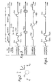
- the slice is taken to lie in the Y-Z plane so that the applied gradient is in the X-direction and is thus denote by G-x in Figure 3.
- G ' x is being applied an RF magnetic field pulse denoted B,(90°) is applied.
- the frequency of the RF pulse is chosen to be at the Larmor frequency of chosen protons, typically hydrogen protons, in the slice of the body to be imaged.
- the strength of the magnetic field and hence the Larmor frequency of the chosen protons outside the slice differs from the frequency of the applied RF pulse, proton spins within the slice only are excited by the RF pulse.
- the integral of the RF pulse is such that the pulse is just sufficient to tip the spins of the excited protons through 90° i.e. in the present case from the Z-direction into the X-Y plane, the spins then precessing in the X-Y plane around the Z-axis.
- the applied magnetic field gradient G f x is then removed and a reverse gradient -G, 'x applied to rephase the spins in the selected slice against dephasing resulting from the gradient across the slice during excitation, as described for example in UK Patent Specification No. 1,578,910 and United States Patent Specification No. 4,284,948.
- a second RF pulse B 2 (90°) identical to the first RF pulse is applied, the pulse B 2 (90°) being accompanied by a second slice selection magnetic field gradient G 2 x identical to the first applied magnetic field gradient G x.
- rephasing is effected by a preceding reverse gradient -Ga'x, identical to gradient -G 'x, rather than by a subsequent reverse gradient.
- a third RF pulse3B (90°) identical to the two preceding RF pulses B 1 (90°) and B 2 (90°) is applied, tB being chosen to be a large fraction of the spin-lattice relaxation time constant T1 of the material in the slice, and being-significantly greater than tA.
- the third pulse is accompanied by a third slice selection magnetic field gradient G 3 x identical to the first and fourth applied gradients G ' x and G 2 x, and is immediately followed by a rephasing gradient -G' 3 x, as in the case of the first RF pulse B 1 (90°).
- the method as so far described produces spin echoes at times 2tA, tB + 2tA, 2tB - 2tA, 2tB and 2tB - 2tA in known manner, the first and second spin echoes E 1 and E 2 only being indicated in Figure 3.
- the spin echo signals must be encoded in known manner to enable the signals arising from different parts of the slice to be distinguished from one another.
- the second spin echo signals may be encoded by a phase encoding magnetic field gradient pulse Giy applied after the third RF pulse Bs(90°) and a frequency encoding magnetic field gradient G 1 Z applied during detection of the second spin echo signal, as shown in Figure 3.
- the excitation and detection sequence is repeated a number of times with different values of the phase encoding gradient Giy.
- a frequency encoding gradient during spin echo detection only is employed and the excitation and detection sequence repeated for different directions of the encoding gradient in the slice.
- the gradients -G 1 'x and -G 2 'x are chosen so that the sum of the integrals of these two gradients alone is sufficient to effect any required rephasing against dephasing produced by the selection gradients G,x, G 2 x, and G 3 x of the spins initially excited by the first RF pulse B 1 (90°). Hence, a third rephasing gradient after the third RF pulse B 3 (90°) is no longer required.
- the spins which were excited by the first RF pulse and have not relaxed to the Z-direction immediately prior to the third RF pulse i.e. the wanted spins
- the wanted spins can be arranged to be rephased after the third RF pulse by suitable choice of gradients -G 1 'x and -Ga'x.
- the period tB may be chosen with a view to enhancing T1 information contained in the image obtained without risk of distorting the image in the manner experienced in known imaging methods employing the Hahn spin echo technique.
Landscapes
- Physics & Mathematics (AREA)
- High Energy & Nuclear Physics (AREA)
- Condensed Matter Physics & Semiconductors (AREA)
- General Physics & Mathematics (AREA)
- Magnetic Resonance Imaging Apparatus (AREA)
Applications Claiming Priority (2)
| Application Number | Priority Date | Filing Date | Title |
|---|---|---|---|
| GB8521791 | 1985-09-02 | ||
| GB858521791A GB8521791D0 (en) | 1985-09-02 | 1985-09-02 | Nuclear magnetic resonance imaging |
Publications (2)
| Publication Number | Publication Date |
|---|---|
| EP0215592A2 true EP0215592A2 (de) | 1987-03-25 |
| EP0215592A3 EP0215592A3 (de) | 1989-01-25 |
Family
ID=10584598
Family Applications (1)
| Application Number | Title | Priority Date | Filing Date |
|---|---|---|---|
| EP86306597A Ceased EP0215592A3 (de) | 1985-09-02 | 1986-08-27 | Apparat und Verfahren zur Bilderzeugung mittels magnetischer Kernresonanz |
Country Status (4)
| Country | Link |
|---|---|
| US (1) | US4703269A (de) |
| EP (1) | EP0215592A3 (de) |
| JP (1) | JPS62129043A (de) |
| GB (1) | GB8521791D0 (de) |
Cited By (2)
| Publication number | Priority date | Publication date | Assignee | Title |
|---|---|---|---|---|
| GB2195024A (en) * | 1986-09-04 | 1988-03-23 | Nat Res Dev | Methods of imaging solids by nmr techniques |
| US4833411A (en) * | 1986-09-04 | 1989-05-23 | National Research Development Corporation | Methods of imaging solids by NMR techniques |
Families Citing this family (4)
| Publication number | Priority date | Publication date | Assignee | Title |
|---|---|---|---|---|
| GB8702951D0 (en) * | 1987-02-10 | 1987-03-18 | Surrey Medical Imaging Systems | Nmr imaging |
| US6272370B1 (en) | 1998-08-07 | 2001-08-07 | The Regents Of University Of Minnesota | MR-visible medical device for neurological interventions using nonlinear magnetic stereotaxis and a method imaging |
| US6463317B1 (en) | 1998-05-19 | 2002-10-08 | Regents Of The University Of Minnesota | Device and method for the endovascular treatment of aneurysms |
| CN102156270A (zh) * | 2011-03-07 | 2011-08-17 | 华东师范大学 | 一种磁共振成像系统磁场梯度延时的校正方法 |
Family Cites Families (4)
| Publication number | Priority date | Publication date | Assignee | Title |
|---|---|---|---|---|
| US4563647A (en) * | 1982-06-09 | 1986-01-07 | Picker International Limited | Nuclear magnetic resonance methods and apparatus |
| DE3378495D1 (en) * | 1982-08-19 | 1988-12-22 | Picker Int Ltd | Nuclear magnetic resonance methods and apparatus |
| JPS5946546A (ja) * | 1982-09-09 | 1984-03-15 | Yokogawa Hokushin Electric Corp | 核磁気共鳴による検査方法及び検査装置 |
| DE3445689A1 (de) * | 1984-12-14 | 1986-06-19 | Max-Planck-Gesellschaft zur Förderung der Wissenschaften e.V., 3400 Göttingen | Verfahren und einrichtung zur ortsaufgeloesten untersuchung einer probe mittels magnetischer resonanz von spinmomenten |
-
1985
- 1985-09-02 GB GB858521791A patent/GB8521791D0/en active Pending
-
1986
- 1986-08-12 US US06/895,895 patent/US4703269A/en not_active Expired - Fee Related
- 1986-08-27 EP EP86306597A patent/EP0215592A3/de not_active Ceased
- 1986-08-30 JP JP61205007A patent/JPS62129043A/ja active Pending
Cited By (3)
| Publication number | Priority date | Publication date | Assignee | Title |
|---|---|---|---|---|
| GB2195024A (en) * | 1986-09-04 | 1988-03-23 | Nat Res Dev | Methods of imaging solids by nmr techniques |
| US4833411A (en) * | 1986-09-04 | 1989-05-23 | National Research Development Corporation | Methods of imaging solids by NMR techniques |
| GB2195024B (en) * | 1986-09-04 | 1990-05-09 | Nat Res Dev | Methods of imaging solids by nmr techniques |
Also Published As
| Publication number | Publication date |
|---|---|
| JPS62129043A (ja) | 1987-06-11 |
| GB8521791D0 (en) | 1985-10-09 |
| US4703269A (en) | 1987-10-27 |
| EP0215592A3 (de) | 1989-01-25 |
Similar Documents
| Publication | Publication Date | Title |
|---|---|---|
| EP0096590B1 (de) | Kernmagnetische Resonanzmethode und Vorrichtung | |
| US4520828A (en) | Nuclear magnetic resonance method and apparatus | |
| US4553096A (en) | Nuclear magnetic resonance method and apparatus | |
| EP0112663B1 (de) | Magnetische Kernresonanzmethode und Vorrichtung | |
| US4733183A (en) | Nuclear magnetic resonance methods and apparatus | |
| EP0161366B1 (de) | Magnetische Kernresonanzmethode und Vorrichtung | |
| EP0103388B1 (de) | Kernmagnetische Resonanzmethode und Vorrichtung | |
| EP0109238B1 (de) | Verfahren und Vorrichtung unter Verwendung der magnetischen Kernresonanz | |
| US4703269A (en) | Nuclear magnetic resonance imaging methods and apparatus | |
| EP0106551B1 (de) | Magnetische Kernresonanzmethode und Vorrichtung | |
| GB2090982A (en) | Nuclear magnetic resonance systems | |
| US4646023A (en) | Nuclear magnetic resonance imaging | |
| EP0223279B1 (de) | Verfahren und Gerät für die Phasenkorrektur von kernspinerzeugenden Bildern mit Hilfe einer Inversion-Rückgewinnungssequenz | |
| US4683432A (en) | Nuclear magnetic resonance methods and apparatus | |
| EP0106472B1 (de) | Magnetische Kernresonanzmethode und -vorrichtung | |
| US5015955A (en) | Magnetic resonance methods | |
| EP0129356A2 (de) | Magnetische Kernresonanzmethode und Vorrichtung | |
| US5227726A (en) | Nuclear magnetic resonance methods and apparatus | |
| GB2127155A (en) | Flow determination by nuclear magnetic resonance | |
| GB2160660A (en) | Nuclear magnetic resonance (NMR) imaging | |
| JPH0363896B2 (de) |
Legal Events
| Date | Code | Title | Description |
|---|---|---|---|
| PUAI | Public reference made under article 153(3) epc to a published international application that has entered the european phase |
Free format text: ORIGINAL CODE: 0009012 |
|
| AK | Designated contracting states |
Kind code of ref document: A2 Designated state(s): DE GB NL |
|
| PUAL | Search report despatched |
Free format text: ORIGINAL CODE: 0009013 |
|
| AK | Designated contracting states |
Kind code of ref document: A3 Designated state(s): DE GB NL |
|
| 17P | Request for examination filed |
Effective date: 19890406 |
|
| 17Q | First examination report despatched |
Effective date: 19900510 |
|
| STAA | Information on the status of an ep patent application or granted ep patent |
Free format text: STATUS: THE APPLICATION HAS BEEN REFUSED |
|
| 18R | Application refused |
Effective date: 19920424 |
|
| RIN1 | Information on inventor provided before grant (corrected) |
Inventor name: YOUNG, IAN ROBERT |