EP0216452A1 - Transportsystem mit schwebenden Transporteinheiten - Google Patents
Transportsystem mit schwebenden Transporteinheiten Download PDFInfo
- Publication number
- EP0216452A1 EP0216452A1 EP86305165A EP86305165A EP0216452A1 EP 0216452 A1 EP0216452 A1 EP 0216452A1 EP 86305165 A EP86305165 A EP 86305165A EP 86305165 A EP86305165 A EP 86305165A EP 0216452 A1 EP0216452 A1 EP 0216452A1
- Authority
- EP
- European Patent Office
- Prior art keywords
- carrier
- guide rail
- gap
- feedback loop
- electromagnets
- Prior art date
- Legal status (The legal status is an assumption and is not a legal conclusion. Google has not performed a legal analysis and makes no representation as to the accuracy of the status listed.)
- Granted
Links
- 230000005291 magnetic effect Effects 0.000 claims abstract description 80
- 238000007667 floating Methods 0.000 claims abstract description 15
- 239000003302 ferromagnetic material Substances 0.000 claims abstract description 6
- 230000004907 flux Effects 0.000 claims description 11
- 230000001133 acceleration Effects 0.000 claims description 9
- 230000004044 response Effects 0.000 claims description 7
- 230000008859 change Effects 0.000 claims description 5
- 238000012546 transfer Methods 0.000 claims description 5
- 238000012544 monitoring process Methods 0.000 claims 2
- 238000010276 construction Methods 0.000 abstract description 6
- 230000009467 reduction Effects 0.000 abstract description 3
- 238000000034 method Methods 0.000 description 20
- 238000010586 diagram Methods 0.000 description 9
- 239000011159 matrix material Substances 0.000 description 6
- 238000001514 detection method Methods 0.000 description 5
- 230000003287 optical effect Effects 0.000 description 4
- 230000008901 benefit Effects 0.000 description 3
- 239000003990 capacitor Substances 0.000 description 3
- 230000008569 process Effects 0.000 description 3
- 230000006641 stabilisation Effects 0.000 description 3
- 238000011105 stabilization Methods 0.000 description 3
- 230000007704 transition Effects 0.000 description 3
- 230000008878 coupling Effects 0.000 description 2
- 238000010168 coupling process Methods 0.000 description 2
- 238000005859 coupling reaction Methods 0.000 description 2
- 230000005484 gravity Effects 0.000 description 2
- 230000006698 induction Effects 0.000 description 2
- 230000010354 integration Effects 0.000 description 2
- 230000007246 mechanism Effects 0.000 description 2
- 230000004048 modification Effects 0.000 description 2
- 238000012986 modification Methods 0.000 description 2
- 230000035699 permeability Effects 0.000 description 2
- 230000003190 augmentative effect Effects 0.000 description 1
- 238000007796 conventional method Methods 0.000 description 1
- 230000004069 differentiation Effects 0.000 description 1
- 238000004134 energy conservation Methods 0.000 description 1
- 238000009434 installation Methods 0.000 description 1
- 230000005389 magnetism Effects 0.000 description 1
- 238000012545 processing Methods 0.000 description 1
- 239000012925 reference material Substances 0.000 description 1
- 230000000284 resting effect Effects 0.000 description 1
- 230000009466 transformation Effects 0.000 description 1
- 230000001131 transforming effect Effects 0.000 description 1
- 125000000391 vinyl group Chemical group [H]C([*])=C([H])[H] 0.000 description 1
- 229920002554 vinyl polymer Polymers 0.000 description 1
Images



Classifications
-
- B—PERFORMING OPERATIONS; TRANSPORTING
- B60—VEHICLES IN GENERAL
- B60L—PROPULSION OF ELECTRICALLY-PROPELLED VEHICLES; SUPPLYING ELECTRIC POWER FOR AUXILIARY EQUIPMENT OF ELECTRICALLY-PROPELLED VEHICLES; ELECTRODYNAMIC BRAKE SYSTEMS FOR VEHICLES IN GENERAL; MAGNETIC SUSPENSION OR LEVITATION FOR VEHICLES; MONITORING OPERATING VARIABLES OF ELECTRICALLY-PROPELLED VEHICLES; ELECTRIC SAFETY DEVICES FOR ELECTRICALLY-PROPELLED VEHICLES
- B60L13/00—Electric propulsion for monorail vehicles, suspension vehicles or rack railways; Magnetic suspension or levitation for vehicles
- B60L13/04—Magnetic suspension or levitation for vehicles
- B60L13/06—Means to sense or control vehicle position or attitude with respect to railway
- B60L13/08—Means to sense or control vehicle position or attitude with respect to railway for the lateral position
-
- B—PERFORMING OPERATIONS; TRANSPORTING
- B61—RAILWAYS
- B61B—RAILWAY SYSTEMS; EQUIPMENT THEREFOR NOT OTHERWISE PROVIDED FOR
- B61B13/00—Other railway systems
- B61B13/08—Sliding or levitation systems
-
- B—PERFORMING OPERATIONS; TRANSPORTING
- B61—RAILWAYS
- B61C—LOCOMOTIVES; MOTOR RAILCARS
- B61C13/00—Locomotives or motor railcars characterised by their application to special systems or purposes
- B61C13/04—Locomotives or motor railcars characterised by their application to special systems or purposes for elevated railways with rigid rails
-
- B—PERFORMING OPERATIONS; TRANSPORTING
- B65—CONVEYING; PACKING; STORING; HANDLING THIN OR FILAMENTARY MATERIAL
- B65G—TRANSPORT OR STORAGE DEVICES, e.g. CONVEYORS FOR LOADING OR TIPPING, SHOP CONVEYOR SYSTEMS OR PNEUMATIC TUBE CONVEYORS
- B65G54/00—Non-mechanical conveyors not otherwise provided for
- B65G54/02—Non-mechanical conveyors not otherwise provided for electrostatic, electric, or magnetic
-
- B—PERFORMING OPERATIONS; TRANSPORTING
- B60—VEHICLES IN GENERAL
- B60L—PROPULSION OF ELECTRICALLY-PROPELLED VEHICLES; SUPPLYING ELECTRIC POWER FOR AUXILIARY EQUIPMENT OF ELECTRICALLY-PROPELLED VEHICLES; ELECTRODYNAMIC BRAKE SYSTEMS FOR VEHICLES IN GENERAL; MAGNETIC SUSPENSION OR LEVITATION FOR VEHICLES; MONITORING OPERATING VARIABLES OF ELECTRICALLY-PROPELLED VEHICLES; ELECTRIC SAFETY DEVICES FOR ELECTRICALLY-PROPELLED VEHICLES
- B60L2200/00—Type of vehicles
- B60L2200/26—Rail vehicles
-
- Y—GENERAL TAGGING OF NEW TECHNOLOGICAL DEVELOPMENTS; GENERAL TAGGING OF CROSS-SECTIONAL TECHNOLOGIES SPANNING OVER SEVERAL SECTIONS OF THE IPC; TECHNICAL SUBJECTS COVERED BY FORMER USPC CROSS-REFERENCE ART COLLECTIONS [XRACs] AND DIGESTS
- Y02—TECHNOLOGIES OR APPLICATIONS FOR MITIGATION OR ADAPTATION AGAINST CLIMATE CHANGE
- Y02T—CLIMATE CHANGE MITIGATION TECHNOLOGIES RELATED TO TRANSPORTATION
- Y02T30/00—Transportation of goods or passengers via railways, e.g. energy recovery or reducing air resistance
Definitions
- the present invention relates to a transportation system of floated carrier type and, more particularly, to a transportation system of floated carrier type which makes it possible to achieve savings in energy and space.
- a transporting system to be used for such purposes must move items to be transported fast and quietly. For this reason, in a transporting system of this kind the carrier is supported on guide rails without making contact with the guide rails.
- air or magnetism is generally used to support the carrier.
- the magnetic support system may be regarded to be more promising, in view of reduced noise and its excellent followability of the guide rails.
- the conventional transporting system of the magnetically floated type is a system for supporting the carrier by means of electromagnets in which the carrier is supported stably through control of the exciting current to the electromagnet. Accordingly, it is necessary to keep the coil of the electromagnet energized at all times which leads to the inevitable drawback that large amounts of electric power are consumed.
- a majority of the magnetomotive force required for the electromagnets is supplied by permanent magnets in order to reduce the power consumed. Even in such a case, however, when an external force is applied to the carrier, by placing cargo on board the carrier, for instance, it becomes necessary to provide a force through electromagnets to push the carrier to its normal position.
- the objects of the present invention are to provide a transporting system of floated carrier type which makes it possible to achieve both energy conservation and space saving through reduction in the electric power consumed.
- the transporting system of floated carrier type in accordance with the present invention is provided with a zero power feedback loop which makes the stationary deviation in current to remain at zero regardless of the presence or absence of the stepwise external forces, and the system is arranged to be operative only when the zero power feedback loop is functioning effectively.
- the transporting system of floated carrier type includes a guide rail having bottom surface sections formed of a ferromagnetic material, a carrier arranged to be freely movable along the guide rails, one or a plurality of magnetic supporting units which consist of an electromagnet arranged to face the bottom surface of the guide rail with a gap inbetween, a permanent magnet situated in the magnetic circuit formed by the electromagnet, the guide rail and the gap for supplying magnetomotive force required for floating the carrier, the electromagnet and the permanent magnet being placed on board the carrier, a sensor section attached to the carrier which detects changes in the magnetic circuit, and a zero power feedback loop in an operational circuit which stabilizes the magnetic circuit to a state for which the current in the magnetic circuit is zero, by controlling the exciting current for the electromagnet based on the output from the sensor section.
- it is equipped with a controlling circuit which causes the zero power feedback loop to operate only when the length of the gap between the electromagnet and the rail is within a predetermined range.
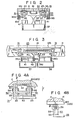
- reference numeral 11 designates a track frame having a cross-sectional form in the shape of an inverted letter U that is laid down in the office space, for example, so as to avoid obstacles.
- a carrier 15 freely movably along the guide rails 12a and 12b.
- a stator 16 for a linear induction motor along the guide rails at a predetermined distance apart from the guide rails.
- the stator 16 is one of many stators which are installed in predetermined positions along the guide rails.
- the guide rails 12a or 12b are formed by pasting a white vinyl tape 22 on the lower surface of a part 21 with the shape of an inverted U that is formed of a ferromagnetic material. It is given a split construction in order to facilitate installation in the office space. For the joining section A of each pair of parts 21 there is given a predetermined bonding processing.
- the support plate 25 is constructed by a pair of divided plates 26a and 26b that are arranged parallel to the rails of running.
- a coupling mechanism 27 links the divided plates 26a and 26b so that they are in turnable in the plane perpendicular to the direction of running of the rails.
- At each of the four corners on the upper surface of the support plate 25 there is mounted a magnetic supporting unit 31.
- These magnetic supporting units 31 are attached to the support plate 25 to be rotatable on the upper surface of the support plate 25 by means of bolts 32 and seats 33.
- On these magnetic supporting units 31 there are installed optical gap sensors 34 for detecting the length of the gap between the units 31 and the guide rails 12a and 12b. Further, on the lower surface of each of the divided.
- the support plate 25 is constructed by a pair of divided plates 26a and 26b that are arranged parallel to the rails of running.
- a coupling mechanism 27 links the divided plates 26a and 26b so that they are in turnable in the plane perpendicular to the direction of running of the rails.
- At each of the four corners on the upper surface of the support plate 25 there is mounted a magnetic supporting unit 31. These magnetic supporting units 31 are attached to the support plate 25 to be rotatable on the upper surface of the support plate 25 by means of bolts 32 and seats 33.
- each of the divided plates 26a and 26b there are installed containers 37 and 38, respectively, for accommodating cargoes via linking parts 35a, 35b, 36a, and 36b.
- control apparatuses 41 for controlling respective of the four magnetic supporting units 31, constant voltage generating apparatuses 42, and small capacity power sources 43.
- each of these wheels in an emergency making contact with the inner surfaces of the upper lower or side walls of the emergency guides 13a and 13b that form a mechanical supporting means for supporting the carrier 15 freely movably with respect to the fixed portions of the track frame.
- the four vertical wheels 45a are mounted on the support plate 25 via piezo-electric rubber elements 46.
- Each piezo-electric rubber element 46 which consists for example, of pressure sensitive sheet, finds itself in an electrically conducting state only when it receives a force through contact of the vertical wheel 45a to the inner surfaces of the upper and lower walls of the emergency guides 13a and 13b. By this arrangement, it controls the zero power feedback loop in the control apparatus as will be described later.
- the support plate 25 serves also as a conduction plate which is a working element of the linear induction motor mentioned earlier, and it is arranged during working of the system at a height which faces and is separated from the stator 16 by a slight gap.
- the magnetic supporting unit 31 includes of a pair of electromagnets 51 and 52, arranged with their upper surfaces so as to face the lower end sections of the guide rails 12a and 12b, in the direction which is perpendicular to the direction of running of the carrier 15.
- Unit 31 further includes a permanent magnet 53 which is placed between the lower side surface of each of the electromagnets 51 and 52, thereby forming an overall shape of the letter U.
- Each of the electromagnets 51 and 52 includes of a yoke 55 formed of a ferromagnetic material and a coil 56 which is wound around the yoke 55.
- Each of the coils 56 are connected in series such that the magnetic fluxes formed by the electromagnets 51 and 52 mutually add up.
- the magnetic circuit formed by the magnetic supporting unit 31 and its periphery namely, the guide rails 12a and 12b, gap P, the yoke 55, and the permanent magnet 53, will be considered.
- the magnetic flux leakage from the magnetic circuit will be neglected.
- the magnetic reluctance Rm for the magnetic circuit can be represented by
- u o is the permeability of the vacuum
- S is the cross-sectional area of the magnetic circuit
- z is the length of the gap
- ⁇ s is the specific permeability of the portion other than the gap section
- 1 is the length of the magnetic circuit of the portion other than the gap.
- the intensity of the magnetic field generated in the gap P in the absence of an exciting current through the coil 56 is denoted Hm
- the length of the permanent magnet 53 is denoted 1m
- the total number of turns of the coil 56 is N
- the exciting current through the coil 56 is I
- the total magnetic flux generated in the magnetic circuit will be given by Therefore
- the total force of attraction F acting between the guide rails 12a, 12b and each of the yokes 55 may be represented by Therefore, denoting the direction of gravity by z
- the equation of motion for the carrier is given by In the above equation, m is the sum of the total mass of the magnetic supporting unit and the mass of the load applied to the magnetic supporting unit, g is the acceleration of gravity, and Um is the external force applied to the magnetic supporting unit.
- the magnetic flux number ⁇ N inter-liked by the coils 56 connected in series is given by so that, denoting the total resistance of the coils 56 by R, the voltage equation for the coils 56 is given by the following:
- I O
- Equations (7) and (8) in the above may be expressed as the following equation of state: Where a21, a23, a32, b33, b31, and d21 are given respectively, by the following.
- Eq. (9) above may be represented by
- the linear system represented by Eq. (9) is unstable in general, it is possible to stabilize it by applying feedback control to the system, i.e., by determining the applied voltage E by various methods from the 'state vector (Az, Az, ⁇ i) represented by Eq. (9) and the acceleration ⁇ z ⁇ .
- Eq. (10) becomes If X is solved by Laplace transforming Eq. (10), there will be obtained where I is the unit matrix and Xo is the initial value for X.
- FIG. 5 A block diagram for the case in which such a feedback control is applied to the magnetic supporting unit of the magnetic floating system is illustrated in Fig. 5.
- a feedback gain compensator C 2 is added to the control object C l .
- Y represents CX.
- the present invention is characterized by that, only when the gap length deviation Az is within a predetermined range, feedback control is applied to the magnetic control unit 31 so as to make the stationary current deviation Ai s , of the stationary deviations given by Eqs. (16) and (17), to be zero, regardless of the presence or absence of a stepwise external force Um.
- the present invention can be implemented by adoption of, for example, one of the following control methods:
- the block diagram for a magnetic floating system employing the method (3) noted above is illustrated by Fig. 6. Namely, in the method, there is augmented an integrating compensator C 3 to the feedback compensator C 2 mentioned earlier, and there is further added a means for arbitrarily interrupting the function of the integrating compensator C 3 .
- the detection of the elements of the state vector X may be carried out, for instance, by one of the following methods.
- the control described in the foregoing will be applied only when the gap P is found within a fixed range.
- the reason for making such an arrangement is to avoid the actuation of the control system by regarding the resistive force from the guide rails 12a and 12b on the carrier 15 as an external force when the state of floatation of the carrier 15 is broken due to its contact with, or attachment to, the guide rails 12a and 12b.
- control apparatus 41 is constructed, for example, as shown in Fig. 7.
- arrows indicate the signal routes while solid lines show the power routes.
- the control apparatus 41 includes a sensor section 61 which is installed on the carrier 15 for detecting the magnetomotive force or magnetic reluctance in the magnetic circuit formed by the magnetic supporting unit 31, or changes in the motion of the carrier 15, an operational circuit 62 for computing electric power to be supplied to the coils 56 based on the signal from the sensor section 61, and a power amplifier 63 for supplying electric power to the coils 56 based on the signal from the operational circuit 62, and four of these combined control each of the four magnetic supporting units 31.
- the sensor section 61 includes a modulation circuit 64 for modulating the signal from the optional gap sensor 34 in order to suppress the influence of external noise and a current detector 65 for detecting the value of the current in the coils 56.
- the operational circuit 62 receives the signal from the optical gap sensor 34 via the modulation circuit 64, subtracts the set value zo for the gap length from the signal by means of a subtractor 66, and introduces the output from the subtractor 66 directly to a feedback gain compensator 68 and via a differentiator 67 to a gain compensator 69, respectively.
- the operational circuit 62 introduces the signal from the current detector 65 to a feedback gain compensator 70, and moreover, it compares at a subtractor 74 the signal, which is obtained by an adder 73 as the resultant of the outputs from the three feedback gain compensators 68-70, with the signal, which is compensated by an integrating compensator 72 after it is received from the current detector 65 and is compared with zero signal at a subtractor 71, in order to output the deviation between the two signals to the power amplifier 63.
- a zero power feedback loop L of a subtractor 71, and integrating compensator 72, and a subtractor 74 By the above arrangement there is formed a zero power feedback loop L of a subtractor 71, and integrating compensator 72, and a subtractor 74.
- a switch 75 for selectively nullifying the function of the integrating compensator 72.
- the switch 75 is actuated in response to the pressure detection by the piezo-electric rubber element 46 described earlier. More specifically, it only needs to be constructed so as to short-circuit the capacitor 82 which is connected between the input and the output of an operational amplifier 81 that forms the integrating compensator 72 by means of the switching operation of the piezo-electric rubber element 46 which takes place at the time of application of pressure.
- the constant voltage generator 42 which is inserted between the power source 43 and the control apparatus 41 supplies currents that are at constant voltage at all times to the modulation circuit 64, the operational circuit 62, and the optical gap sensor 34.
- the constant voltage generator 42 eliminates any influence on the control apparatus 41 from voltage lowering caused by the variation in the load of the power source 43, and is constructed by a reference voltage generating unit 76 and a current amplifier 77 which supplies required current at constant voltage at all times to the control apparatus 41 based on the output signal from the reference voltage generator 76.
- the zero power feedback loop L that includes the integrating compensator 72 will not be actuated since the vertical wheels 45a of the carrier 15 are making contact with either of the upper or lower walls of the emergency guides 13a and 13b, and hence a pressure is applied to the piezo-electric rubber 46. Accordingly, the system will not be controlled with the resistive force from the emergency guides 13a and 13b as an external force.
- the control apparatus 41 causes generation of magnetic flux in the electromagnets 51 and 52 in the same direction or in the opposite direction to the magnetic flux generated by the permanent magnet 53, and controls the current flowing in the exciting coils 56 so as to create a gap with predetermined width between the magnetic supporting unit 31 and the guide rails 12a and 12b.
- the control apparatus 41 causes generation of magnetic flux in the electromagnets 51 and 52 in the same direction or in the opposite direction to the magnetic flux generated by the permanent magnet 53, and controls the current flowing in the exciting coils 56 so as to create a gap with predetermined width between the magnetic supporting unit 31 and the guide rails 12a and 12b.
- a magnetic circuit in the route of the permanent magnet 53, yoke 55, gap P, guide rail 12a (12b), gap P, yoke 55, and back to the permanent magnet 53, as shown in Fig. 4A.
- the magnetic flux t formed in this magnetic circuit is generated, as shown in Fig.
- the magnetic circuit maintains a predetermined gap length zo so as to generate a magnetic force of attraction which does not at all require magnetic fluxes due to the electromagnets 51 and 52, under the state in which there is applied no external force on the carrier 15.
- the gap sensor 34 detects it and sends out the detection signal to the operational circuit 62 via the modulation circuit 64.
- the operational circuit 62 subtracts the set value z o of the gap length from the above signal by means of the subtractor 66 to compute the gap length deviation signal Az.
- the gap length deviation signal ⁇ z is input to the feedback gain compensator 69, and is input also to the feedback gain compensator 68 after it is converted to a velocity deviation signal ⁇ by the differentiator 67.
- the current deviation signal Ai which is obtained from the measured signal of the current detector 65 is input to the feedback gain compensator 70.
- the current deviation signal Ai is compared with the zero level by the subtractor 71 and the difference signal is input to the integrating compensator 72. Then, the output signal obtained by summing the outputs from the three feedback gain compensators 68 to 70 and the signal from the integrating compensator 72 are fed back, with gains respectively added, to the power amplifier 63. In this way, the system will be stabilized to a state in which the current deviation Ai vanishes.
- the zero power feedback loop stops functioning so that it becomes possible to go back immediately to the floated situation.
- the present invention is not limited to the embodiments described in the foregoing.
- the method employed in the above embodiments in which the current deviation Ai is integrated by an integrating compensator and the result of which is fed back with a suitably given gain may be arranged to be controlled by other methods that are described in the foregoing.
- the arrangement illustrated by Fig. 9 in an example in which the integrating compensation in Fig. 7 is replaced by a filter 91 with first order transfer function.
- T f time constant of the filter 91
- the output of the current detector 65 is given as the input to the subtractor in the examples described earlier, it is given by the output of the subtractor 66 in the present example.
- the filter 91 is constructed, for example, by connecting a capacitor 93 and a resistor 94 between the input and the output of the operational amplifier 92, as shown by Fig. 10.
- the function of the zero power feedback loop L can be interrupted by short circuiting both ends of the capacitor 93 and the resistor 94 by the piezo-electric rubber element 46.
- Fig. 12 shows the control method that employs a state observer 101.
- the state observer 101 detects the velocity Az that corresponds to the output of the differentiator 67 in the previous example and the stationary component in the external force Um applied to the carrier 15, by receiving the output signals of the subtractor 66 and the current detector 65 as the inputs, and outputs the gap length deviation signal, the velocity signal, the current deviation signal, and the signal for stationary component of the external force that are to become the inputs to the feedback gain compensators 68, 69, 70, and 102, respectively.
- the four feedback gain compensators 68 to 70 and 102 output the results in which the inputs are multiplied by the gains F 1 , F 2 , F 3 and F 4 , respectively. These outputs are summed at an adder 103, and the result is output to the amplifier 63 after being compared with the zero signal at the subtractor 74.
- F 4 is given by
- Fig. 13 is illustrated a block diagram for the control system.
- the construction of the state observer 101 is shown by C 5 in the figure.
- C 5 the construction of the state observer 101
- the periphery of the feedback gain compensator 102 is constructed as shown by Fig. 14, for example, to be able to short-circuit a resistor 107 which is connected between the input and the output of an operational amplifier 106 by controlling the ON-OFF operation of a contactless relay 105 with the signal from a comparator 104.
- the comparator 104 outputs a signal that causes the contactless relay 105 to be turned off if the gap P is within the range of a minimum gap length z min and a maximum gap length z max that are set in advance, and outputs otherwise a signal that causes it to be turned on, to interrupt the operation of the zero power feedback loop L.
- the velocity deviation Az can be measured without the use of a differentiator so that it becomes possible to minimize the influence of the external electrical noise on the carrier 15 which is kept floating. Moreover, since the operation of the zero power feedback loop L is feasible under the state in which the carrier 15 is not making contact with the guide rails 12a and 12b, it becomes possible to reduce the impact on the carrier 15 compared with the case in which use is made of the piezo-electric rubber element 46.
- the present invention can be applied to the case of the velocity sensor or the acceleration sensor instead of the gap sensor 34 and the current detector 65.
- the gap length detection can be achieved by integrating the output of the acceleration sensor twice.
- the position for setting the sensor can arbitrarily be chosen within a range in which it is possible to accomplish the detection of the acceleration of the magnetic supporting unit 31.
- a method for detecting the range in which the zero power feedback control is to be made use can be made of means such as the limit switch other than the piezo-electric rubber element or a comparator.
- the present invention may be applied to any kind of construction so long as it is a control apparatus equipped with a zero power feedback control system, irrespective of its being analog or digital.
- the present invention current flows in the coils for the electromagnet only transitionally at the time of application of an external force to the carrier since it is arranged that the part that corresponds to the magnetic force required by the electromagnets is compensated by a permanent magnet, and further, that the stationary value of the exciting current that flows in the electromagnets is set to be zero regardless of whether or not there is present an external force applied to the carrier. Therefore, according to the present invention, it is to reduce the power consumed in the coil markedly compared with the conventional method, reducing the burden on the power source. In other words, the present invention can contribute substantially toward conservation of energy.
- the present invention avoids the inconvenience of having the system controlled by detecting a contact or attachment of the carrier to the guide rails for some reason, such as due to an external force, since it is designed to let the zero power feedback loop function only when the gap length is within a predetermined range. Therefore, it is possible to revert immediately to the floated state without excessive power consumption by the electromagnets. This fact signifies on the one hand that there will take place a smooth transition of the system from the attached state at the start to the floated state, and on the other hand, that there will exist no possibility of having stoppage by attachment of the carrier to the guide rails during its running.
Landscapes
- Engineering & Computer Science (AREA)
- Transportation (AREA)
- Mechanical Engineering (AREA)
- Physics & Mathematics (AREA)
- Electromagnetism (AREA)
- Power Engineering (AREA)
- Control Of Vehicles With Linear Motors And Vehicles That Are Magnetically Levitated (AREA)
Applications Claiming Priority (2)
| Application Number | Priority Date | Filing Date | Title |
|---|---|---|---|
| JP146037/85 | 1985-07-03 | ||
| JP60146037A JPH0624405B2 (ja) | 1985-07-03 | 1985-07-03 | 浮上式搬送装置 |
Publications (2)
| Publication Number | Publication Date |
|---|---|
| EP0216452A1 true EP0216452A1 (de) | 1987-04-01 |
| EP0216452B1 EP0216452B1 (de) | 1990-03-14 |
Family
ID=15398678
Family Applications (1)
| Application Number | Title | Priority Date | Filing Date |
|---|---|---|---|
| EP86305165A Expired - Lifetime EP0216452B1 (de) | 1985-07-03 | 1986-07-03 | Transportsystem mit schwebenden Transporteinheiten |
Country Status (4)
| Country | Link |
|---|---|
| US (1) | US4825773A (de) |
| EP (1) | EP0216452B1 (de) |
| JP (1) | JPH0624405B2 (de) |
| DE (1) | DE3669485D1 (de) |
Cited By (4)
| Publication number | Priority date | Publication date | Assignee | Title |
|---|---|---|---|---|
| DE4133114A1 (de) * | 1991-10-05 | 1993-04-08 | Michael Rupp | Foerdersystem fuer stueckgut |
| WO1997042389A1 (de) * | 1996-05-08 | 1997-11-13 | Schuster Heinz Peter | Elektromagnetisches antriebssystem für magnetische schwebe- und tragesysteme |
| EP3807198A1 (de) * | 2018-06-15 | 2021-04-21 | Krones AG | Mover für ein langstator-system |
| EP3967541A1 (de) * | 2017-07-27 | 2022-03-16 | Hyperloop Technologies, Inc. | Erweitertes permanentmagnetsystem |
Families Citing this family (18)
| Publication number | Priority date | Publication date | Assignee | Title |
|---|---|---|---|---|
| JP2732562B2 (ja) * | 1986-05-14 | 1998-03-30 | 株式会社東芝 | 浮上式搬送装置 |
| US5170714A (en) * | 1988-06-13 | 1992-12-15 | Asahi Glass Company, Ltd. | Vacuum processing apparatus and transportation system thereof |
| EP0346815A3 (de) * | 1988-06-13 | 1990-12-19 | Asahi Glass Company Ltd. | Vakuumbehandlungsvorrichtung und deren Transportsystem |
| JPH02206306A (ja) * | 1989-02-02 | 1990-08-16 | Tsubakimoto Chain Co | リニアモータ式搬送装置 |
| US5016238A (en) * | 1989-02-03 | 1991-05-14 | Eastman Kodak Company | Linear actuator for radial access in disk recorder/player |
| JPH0349588A (ja) * | 1989-07-14 | 1991-03-04 | Omron Corp | 離散時間型acモータ制御装置 |
| US5641054A (en) * | 1992-07-07 | 1997-06-24 | Ebara Corporation | Magnetic levitation conveyor apparatus |
| JPH0630508A (ja) * | 1992-07-08 | 1994-02-04 | Tamagawa Seiki Co Ltd | 磁気浮上方法 |
| US6060813A (en) * | 1998-01-08 | 2000-05-09 | Xerox Corporation | Vibration suppression and electromechanical damping apparatus for electrophotographic printing structures |
| JP4587519B2 (ja) * | 2000-03-16 | 2010-11-24 | 東芝エレベータ株式会社 | エレベータ案内装置 |
| JP3681700B2 (ja) * | 2002-03-14 | 2005-08-10 | ファナック株式会社 | Acモータ制御用のインバータ装置 |
| JP5483692B2 (ja) * | 2009-12-14 | 2014-05-07 | 東芝エレベータ株式会社 | 磁気浮上装置 |
| JP2012125067A (ja) * | 2010-12-09 | 2012-06-28 | Toshiba Elevator Co Ltd | 磁気浮上装置 |
| CN107614314B (zh) * | 2015-05-29 | 2020-08-04 | 株式会社安川电机 | 输送系统以及输送设备构建方法 |
| DE102018118814B4 (de) | 2018-08-02 | 2024-07-18 | Beckhoff Automation Gmbh | Verfahren zum Identifizieren eines Schlittens eines linearen Transportsystems |
| JP7316782B2 (ja) * | 2018-12-14 | 2023-07-28 | キヤノントッキ株式会社 | 蒸着装置、電子デバイスの製造装置、および、蒸着方法 |
| US11413987B2 (en) * | 2019-09-03 | 2022-08-16 | The Boeing Company | Electromagnetic seat attachment and seat power |
| CN113526011B (zh) * | 2021-07-22 | 2022-09-13 | 江西理工大学 | 一种低能耗物流永磁传送带 |
Citations (5)
| Publication number | Priority date | Publication date | Assignee | Title |
|---|---|---|---|---|
| US1371713A (en) * | 1920-01-27 | 1921-03-15 | Ward Radcliffe | Suspended railway-vehicle |
| US3849724A (en) * | 1971-11-17 | 1974-11-19 | Krauss Maffei Ag | Method and apparatus for measuring the gap spacing and relative transverse displacement of an electromagnetic core from an armature using magnetic field sensors |
| US4140063A (en) * | 1977-02-26 | 1979-02-20 | Japan Airlines Co., Ltd. | Electromagnetic suspension and guide system for magnetically suspended vehicle |
| DE3021809A1 (de) * | 1980-06-11 | 1981-12-24 | Messerschmitt-Bölkow-Blohm GmbH, 8000 München | Regelungsanordnung zur schwebefuehrung eines magnetisch getragenen schwebefahrzeuges |
| DE3143512A1 (de) * | 1981-11-03 | 1983-05-11 | Messerschmitt-Bölkow-Blohm GmbH, 8000 München | Regelsystem fuer magnetschwebefahrzeuge |
Family Cites Families (2)
| Publication number | Priority date | Publication date | Assignee | Title |
|---|---|---|---|---|
| US4395165A (en) * | 1980-12-19 | 1983-07-26 | International Business Machine Corp. | Chip shuttle track |
| JPS6096106A (ja) * | 1983-10-26 | 1985-05-29 | Toshiba Corp | 浮上式搬送システムの磁気支持装置 |
-
1985
- 1985-07-03 JP JP60146037A patent/JPH0624405B2/ja not_active Expired - Lifetime
-
1986
- 1986-07-03 EP EP86305165A patent/EP0216452B1/de not_active Expired - Lifetime
- 1986-07-03 DE DE8686305165T patent/DE3669485D1/de not_active Expired - Lifetime
-
1987
- 1987-12-14 US US07/134,609 patent/US4825773A/en not_active Expired - Lifetime
Patent Citations (5)
| Publication number | Priority date | Publication date | Assignee | Title |
|---|---|---|---|---|
| US1371713A (en) * | 1920-01-27 | 1921-03-15 | Ward Radcliffe | Suspended railway-vehicle |
| US3849724A (en) * | 1971-11-17 | 1974-11-19 | Krauss Maffei Ag | Method and apparatus for measuring the gap spacing and relative transverse displacement of an electromagnetic core from an armature using magnetic field sensors |
| US4140063A (en) * | 1977-02-26 | 1979-02-20 | Japan Airlines Co., Ltd. | Electromagnetic suspension and guide system for magnetically suspended vehicle |
| DE3021809A1 (de) * | 1980-06-11 | 1981-12-24 | Messerschmitt-Bölkow-Blohm GmbH, 8000 München | Regelungsanordnung zur schwebefuehrung eines magnetisch getragenen schwebefahrzeuges |
| DE3143512A1 (de) * | 1981-11-03 | 1983-05-11 | Messerschmitt-Bölkow-Blohm GmbH, 8000 München | Regelsystem fuer magnetschwebefahrzeuge |
Cited By (7)
| Publication number | Priority date | Publication date | Assignee | Title |
|---|---|---|---|---|
| DE4133114A1 (de) * | 1991-10-05 | 1993-04-08 | Michael Rupp | Foerdersystem fuer stueckgut |
| WO1997042389A1 (de) * | 1996-05-08 | 1997-11-13 | Schuster Heinz Peter | Elektromagnetisches antriebssystem für magnetische schwebe- und tragesysteme |
| EP3967541A1 (de) * | 2017-07-27 | 2022-03-16 | Hyperloop Technologies, Inc. | Erweitertes permanentmagnetsystem |
| US11724601B2 (en) | 2017-07-27 | 2023-08-15 | Hyperloop Technologies, Inc. | Augmented permanent magnet system |
| EP4230467A1 (de) * | 2017-07-27 | 2023-08-23 | Hyperloop Technologies, Inc. | Erweitertes permanentmagnetsystem |
| EP3807198A1 (de) * | 2018-06-15 | 2021-04-21 | Krones AG | Mover für ein langstator-system |
| EP3807198B1 (de) * | 2018-06-15 | 2025-07-23 | Krones AG | Mover für ein langstator-system |
Also Published As
| Publication number | Publication date |
|---|---|
| JPH0624405B2 (ja) | 1994-03-30 |
| JPS627304A (ja) | 1987-01-14 |
| EP0216452B1 (de) | 1990-03-14 |
| DE3669485D1 (de) | 1990-04-19 |
| US4825773A (en) | 1989-05-02 |
Similar Documents
| Publication | Publication Date | Title |
|---|---|---|
| EP0216452B1 (de) | Transportsystem mit schwebenden Transporteinheiten | |
| EP0179188B1 (de) | Transportsystem vom Typ mit schwebendem Träger | |
| US4838172A (en) | Transporting system of floated carrier type | |
| US4690066A (en) | Electromagnetically floated carrier system with stopping unit | |
| EP0580107A1 (de) | Magnetschwebetransportsystem | |
| US4882999A (en) | Transportation system of a floated-carrier type | |
| JP2553043B2 (ja) | 浮上式搬送装置 | |
| JP2967822B2 (ja) | 浮上式搬送装置 | |
| JPS627305A (ja) | 浮上式搬送装置 | |
| JP2793240B2 (ja) | 浮上式搬送装置 | |
| EP0487744B1 (de) | Lineare unterwassertransportvorrichtung | |
| JPH01152905A (ja) | 磁気浮上搬送装置 | |
| JPH0847112A (ja) | 浮上式搬送装置 | |
| JPH06101884B2 (ja) | 浮上式搬送装置 | |
| JPH05199614A (ja) | 浮上式搬送装置 | |
| JP2547725B2 (ja) | 浮上式搬送装置 | |
| JPH05199615A (ja) | 浮上式搬送装置 | |
| JPH0728481B2 (ja) | 浮上式搬送装置 | |
| JPH0458247B2 (de) | ||
| JP2760495B2 (ja) | 浮上式搬送装置 | |
| JP2713885B2 (ja) | 浮上式搬送装置 | |
| JPH06319208A (ja) | 浮上式搬送装置 | |
| JPH0345106A (ja) | 磁気浮上式搬送装置 | |
| JPS61170206A (ja) | 輝上式搬送装置 | |
| JPH03159503A (ja) | 磁気浮上式搬送装置 |
Legal Events
| Date | Code | Title | Description |
|---|---|---|---|
| PUAI | Public reference made under article 153(3) epc to a published international application that has entered the european phase |
Free format text: ORIGINAL CODE: 0009012 |
|
| AK | Designated contracting states |
Kind code of ref document: A1 Designated state(s): DE FR GB |
|
| 17P | Request for examination filed |
Effective date: 19870907 |
|
| 17Q | First examination report despatched |
Effective date: 19880502 |
|
| GRAA | (expected) grant |
Free format text: ORIGINAL CODE: 0009210 |
|
| AK | Designated contracting states |
Kind code of ref document: B1 Designated state(s): DE FR GB |
|
| REF | Corresponds to: |
Ref document number: 3669485 Country of ref document: DE Date of ref document: 19900419 |
|
| ET | Fr: translation filed | ||
| PLBE | No opposition filed within time limit |
Free format text: ORIGINAL CODE: 0009261 |
|
| STAA | Information on the status of an ep patent application or granted ep patent |
Free format text: STATUS: NO OPPOSITION FILED WITHIN TIME LIMIT |
|
| 26N | No opposition filed | ||
| PGFP | Annual fee paid to national office [announced via postgrant information from national office to epo] |
Ref country code: GB Payment date: 19970624 Year of fee payment: 12 |
|
| PGFP | Annual fee paid to national office [announced via postgrant information from national office to epo] |
Ref country code: FR Payment date: 19970709 Year of fee payment: 12 |
|
| PGFP | Annual fee paid to national office [announced via postgrant information from national office to epo] |
Ref country code: DE Payment date: 19970714 Year of fee payment: 12 |
|
| PG25 | Lapsed in a contracting state [announced via postgrant information from national office to epo] |
Ref country code: GB Free format text: LAPSE BECAUSE OF NON-PAYMENT OF DUE FEES Effective date: 19980703 |
|
| GBPC | Gb: european patent ceased through non-payment of renewal fee |
Effective date: 19980703 |
|
| PG25 | Lapsed in a contracting state [announced via postgrant information from national office to epo] |
Ref country code: FR Free format text: LAPSE BECAUSE OF NON-PAYMENT OF DUE FEES Effective date: 19990331 |
|
| PG25 | Lapsed in a contracting state [announced via postgrant information from national office to epo] |
Ref country code: DE Free format text: LAPSE BECAUSE OF NON-PAYMENT OF DUE FEES Effective date: 19990501 |
|
| REG | Reference to a national code |
Ref country code: FR Ref legal event code: ST |