EP0218023A1 - Geschweisster Kunststoffverschluss für Kunststoffbehälter, Verfahren zur Herstellung desselben und Vorrichtung zur Durchführung des Verfahrens - Google Patents
Geschweisster Kunststoffverschluss für Kunststoffbehälter, Verfahren zur Herstellung desselben und Vorrichtung zur Durchführung des Verfahrens Download PDFInfo
- Publication number
- EP0218023A1 EP0218023A1 EP86109837A EP86109837A EP0218023A1 EP 0218023 A1 EP0218023 A1 EP 0218023A1 EP 86109837 A EP86109837 A EP 86109837A EP 86109837 A EP86109837 A EP 86109837A EP 0218023 A1 EP0218023 A1 EP 0218023A1
- Authority
- EP
- European Patent Office
- Prior art keywords
- edge
- closure
- neck
- plastic
- container
- Prior art date
- Legal status (The legal status is an assumption and is not a legal conclusion. Google has not performed a legal analysis and makes no representation as to the accuracy of the status listed.)
- Granted
Links
Images



Classifications
-
- B—PERFORMING OPERATIONS; TRANSPORTING
- B29—WORKING OF PLASTICS; WORKING OF SUBSTANCES IN A PLASTIC STATE IN GENERAL
- B29C—SHAPING OR JOINING OF PLASTICS; SHAPING OF MATERIAL IN A PLASTIC STATE, NOT OTHERWISE PROVIDED FOR; AFTER-TREATMENT OF THE SHAPED PRODUCTS, e.g. REPAIRING
- B29C65/00—Joining or sealing of preformed parts, e.g. welding of plastics materials; Apparatus therefor
- B29C65/02—Joining or sealing of preformed parts, e.g. welding of plastics materials; Apparatus therefor by heating, with or without pressure
- B29C65/18—Joining or sealing of preformed parts, e.g. welding of plastics materials; Apparatus therefor by heating, with or without pressure using heated tools
-
- B—PERFORMING OPERATIONS; TRANSPORTING
- B29—WORKING OF PLASTICS; WORKING OF SUBSTANCES IN A PLASTIC STATE IN GENERAL
- B29C—SHAPING OR JOINING OF PLASTICS; SHAPING OF MATERIAL IN A PLASTIC STATE, NOT OTHERWISE PROVIDED FOR; AFTER-TREATMENT OF THE SHAPED PRODUCTS, e.g. REPAIRING
- B29C65/00—Joining or sealing of preformed parts, e.g. welding of plastics materials; Apparatus therefor
- B29C65/02—Joining or sealing of preformed parts, e.g. welding of plastics materials; Apparatus therefor by heating, with or without pressure
-
- B—PERFORMING OPERATIONS; TRANSPORTING
- B29—WORKING OF PLASTICS; WORKING OF SUBSTANCES IN A PLASTIC STATE IN GENERAL
- B29C—SHAPING OR JOINING OF PLASTICS; SHAPING OF MATERIAL IN A PLASTIC STATE, NOT OTHERWISE PROVIDED FOR; AFTER-TREATMENT OF THE SHAPED PRODUCTS, e.g. REPAIRING
- B29C65/00—Joining or sealing of preformed parts, e.g. welding of plastics materials; Apparatus therefor
- B29C65/02—Joining or sealing of preformed parts, e.g. welding of plastics materials; Apparatus therefor by heating, with or without pressure
- B29C65/08—Joining or sealing of preformed parts, e.g. welding of plastics materials; Apparatus therefor by heating, with or without pressure using ultrasonic vibrations
-
- B—PERFORMING OPERATIONS; TRANSPORTING
- B29—WORKING OF PLASTICS; WORKING OF SUBSTANCES IN A PLASTIC STATE IN GENERAL
- B29C—SHAPING OR JOINING OF PLASTICS; SHAPING OF MATERIAL IN A PLASTIC STATE, NOT OTHERWISE PROVIDED FOR; AFTER-TREATMENT OF THE SHAPED PRODUCTS, e.g. REPAIRING
- B29C65/00—Joining or sealing of preformed parts, e.g. welding of plastics materials; Apparatus therefor
- B29C65/02—Joining or sealing of preformed parts, e.g. welding of plastics materials; Apparatus therefor by heating, with or without pressure
- B29C65/18—Joining or sealing of preformed parts, e.g. welding of plastics materials; Apparatus therefor by heating, with or without pressure using heated tools
- B29C65/24—Joining or sealing of preformed parts, e.g. welding of plastics materials; Apparatus therefor by heating, with or without pressure using heated tools characterised by the means for heating the tool
- B29C65/30—Electrical means
- B29C65/32—Induction
-
- B—PERFORMING OPERATIONS; TRANSPORTING
- B29—WORKING OF PLASTICS; WORKING OF SUBSTANCES IN A PLASTIC STATE IN GENERAL
- B29C—SHAPING OR JOINING OF PLASTICS; SHAPING OF MATERIAL IN A PLASTIC STATE, NOT OTHERWISE PROVIDED FOR; AFTER-TREATMENT OF THE SHAPED PRODUCTS, e.g. REPAIRING
- B29C65/00—Joining or sealing of preformed parts, e.g. welding of plastics materials; Apparatus therefor
- B29C65/72—Joining or sealing of preformed parts, e.g. welding of plastics materials; Apparatus therefor by combined operations or combined techniques, e.g. welding and stitching
-
- B—PERFORMING OPERATIONS; TRANSPORTING
- B29—WORKING OF PLASTICS; WORKING OF SUBSTANCES IN A PLASTIC STATE IN GENERAL
- B29C—SHAPING OR JOINING OF PLASTICS; SHAPING OF MATERIAL IN A PLASTIC STATE, NOT OTHERWISE PROVIDED FOR; AFTER-TREATMENT OF THE SHAPED PRODUCTS, e.g. REPAIRING
- B29C66/00—General aspects of processes or apparatus for joining preformed parts
- B29C66/01—General aspects dealing with the joint area or with the area to be joined
- B29C66/05—Particular design of joint configurations
- B29C66/10—Particular design of joint configurations particular design of the joint cross-sections
- B29C66/11—Joint cross-sections comprising a single joint-segment, i.e. one of the parts to be joined comprising a single joint-segment in the joint cross-section
- B29C66/112—Single lapped joints
-
- B—PERFORMING OPERATIONS; TRANSPORTING
- B29—WORKING OF PLASTICS; WORKING OF SUBSTANCES IN A PLASTIC STATE IN GENERAL
- B29C—SHAPING OR JOINING OF PLASTICS; SHAPING OF MATERIAL IN A PLASTIC STATE, NOT OTHERWISE PROVIDED FOR; AFTER-TREATMENT OF THE SHAPED PRODUCTS, e.g. REPAIRING
- B29C66/00—General aspects of processes or apparatus for joining preformed parts
- B29C66/01—General aspects dealing with the joint area or with the area to be joined
- B29C66/05—Particular design of joint configurations
- B29C66/10—Particular design of joint configurations particular design of the joint cross-sections
- B29C66/11—Joint cross-sections comprising a single joint-segment, i.e. one of the parts to be joined comprising a single joint-segment in the joint cross-section
- B29C66/114—Single butt joints
-
- B—PERFORMING OPERATIONS; TRANSPORTING
- B29—WORKING OF PLASTICS; WORKING OF SUBSTANCES IN A PLASTIC STATE IN GENERAL
- B29C—SHAPING OR JOINING OF PLASTICS; SHAPING OF MATERIAL IN A PLASTIC STATE, NOT OTHERWISE PROVIDED FOR; AFTER-TREATMENT OF THE SHAPED PRODUCTS, e.g. REPAIRING
- B29C66/00—General aspects of processes or apparatus for joining preformed parts
- B29C66/01—General aspects dealing with the joint area or with the area to be joined
- B29C66/05—Particular design of joint configurations
- B29C66/10—Particular design of joint configurations particular design of the joint cross-sections
- B29C66/12—Joint cross-sections combining only two joint-segments; Tongue and groove joints; Tenon and mortise joints; Stepped joint cross-sections
- B29C66/122—Joint cross-sections combining only two joint-segments, i.e. one of the parts to be joined comprising only two joint-segments in the joint cross-section
- B29C66/1222—Joint cross-sections combining only two joint-segments, i.e. one of the parts to be joined comprising only two joint-segments in the joint cross-section comprising at least a lapped joint-segment
-
- B—PERFORMING OPERATIONS; TRANSPORTING
- B29—WORKING OF PLASTICS; WORKING OF SUBSTANCES IN A PLASTIC STATE IN GENERAL
- B29C—SHAPING OR JOINING OF PLASTICS; SHAPING OF MATERIAL IN A PLASTIC STATE, NOT OTHERWISE PROVIDED FOR; AFTER-TREATMENT OF THE SHAPED PRODUCTS, e.g. REPAIRING
- B29C66/00—General aspects of processes or apparatus for joining preformed parts
- B29C66/01—General aspects dealing with the joint area or with the area to be joined
- B29C66/05—Particular design of joint configurations
- B29C66/10—Particular design of joint configurations particular design of the joint cross-sections
- B29C66/12—Joint cross-sections combining only two joint-segments; Tongue and groove joints; Tenon and mortise joints; Stepped joint cross-sections
- B29C66/122—Joint cross-sections combining only two joint-segments, i.e. one of the parts to be joined comprising only two joint-segments in the joint cross-section
- B29C66/1224—Joint cross-sections combining only two joint-segments, i.e. one of the parts to be joined comprising only two joint-segments in the joint cross-section comprising at least a butt joint-segment
-
- B—PERFORMING OPERATIONS; TRANSPORTING
- B29—WORKING OF PLASTICS; WORKING OF SUBSTANCES IN A PLASTIC STATE IN GENERAL
- B29C—SHAPING OR JOINING OF PLASTICS; SHAPING OF MATERIAL IN A PLASTIC STATE, NOT OTHERWISE PROVIDED FOR; AFTER-TREATMENT OF THE SHAPED PRODUCTS, e.g. REPAIRING
- B29C66/00—General aspects of processes or apparatus for joining preformed parts
- B29C66/01—General aspects dealing with the joint area or with the area to be joined
- B29C66/05—Particular design of joint configurations
- B29C66/10—Particular design of joint configurations particular design of the joint cross-sections
- B29C66/13—Single flanged joints; Fin-type joints; Single hem joints; Edge joints; Interpenetrating fingered joints; Other specific particular designs of joint cross-sections not provided for in groups B29C66/11 - B29C66/12
- B29C66/131—Single flanged joints, i.e. one of the parts to be joined being rigid and flanged in the joint area
-
- B—PERFORMING OPERATIONS; TRANSPORTING
- B29—WORKING OF PLASTICS; WORKING OF SUBSTANCES IN A PLASTIC STATE IN GENERAL
- B29C—SHAPING OR JOINING OF PLASTICS; SHAPING OF MATERIAL IN A PLASTIC STATE, NOT OTHERWISE PROVIDED FOR; AFTER-TREATMENT OF THE SHAPED PRODUCTS, e.g. REPAIRING
- B29C66/00—General aspects of processes or apparatus for joining preformed parts
- B29C66/01—General aspects dealing with the joint area or with the area to be joined
- B29C66/05—Particular design of joint configurations
- B29C66/10—Particular design of joint configurations particular design of the joint cross-sections
- B29C66/13—Single flanged joints; Fin-type joints; Single hem joints; Edge joints; Interpenetrating fingered joints; Other specific particular designs of joint cross-sections not provided for in groups B29C66/11 - B29C66/12
- B29C66/131—Single flanged joints, i.e. one of the parts to be joined being rigid and flanged in the joint area
- B29C66/1312—Single flange to flange joints, the parts to be joined being rigid
-
- B—PERFORMING OPERATIONS; TRANSPORTING
- B29—WORKING OF PLASTICS; WORKING OF SUBSTANCES IN A PLASTIC STATE IN GENERAL
- B29C—SHAPING OR JOINING OF PLASTICS; SHAPING OF MATERIAL IN A PLASTIC STATE, NOT OTHERWISE PROVIDED FOR; AFTER-TREATMENT OF THE SHAPED PRODUCTS, e.g. REPAIRING
- B29C66/00—General aspects of processes or apparatus for joining preformed parts
- B29C66/01—General aspects dealing with the joint area or with the area to be joined
- B29C66/05—Particular design of joint configurations
- B29C66/10—Particular design of joint configurations particular design of the joint cross-sections
- B29C66/13—Single flanged joints; Fin-type joints; Single hem joints; Edge joints; Interpenetrating fingered joints; Other specific particular designs of joint cross-sections not provided for in groups B29C66/11 - B29C66/12
- B29C66/137—Beaded-edge joints or bead seals
-
- B—PERFORMING OPERATIONS; TRANSPORTING
- B29—WORKING OF PLASTICS; WORKING OF SUBSTANCES IN A PLASTIC STATE IN GENERAL
- B29C—SHAPING OR JOINING OF PLASTICS; SHAPING OF MATERIAL IN A PLASTIC STATE, NOT OTHERWISE PROVIDED FOR; AFTER-TREATMENT OF THE SHAPED PRODUCTS, e.g. REPAIRING
- B29C66/00—General aspects of processes or apparatus for joining preformed parts
- B29C66/01—General aspects dealing with the joint area or with the area to be joined
- B29C66/345—Progressively making the joint, e.g. starting from the middle
- B29C66/3452—Making complete joints by combining partial joints
-
- B—PERFORMING OPERATIONS; TRANSPORTING
- B29—WORKING OF PLASTICS; WORKING OF SUBSTANCES IN A PLASTIC STATE IN GENERAL
- B29C—SHAPING OR JOINING OF PLASTICS; SHAPING OF MATERIAL IN A PLASTIC STATE, NOT OTHERWISE PROVIDED FOR; AFTER-TREATMENT OF THE SHAPED PRODUCTS, e.g. REPAIRING
- B29C66/00—General aspects of processes or apparatus for joining preformed parts
- B29C66/50—General aspects of joining tubular articles; General aspects of joining long products, i.e. bars or profiled elements; General aspects of joining single elements to tubular articles, hollow articles or bars; General aspects of joining several hollow-preforms to form hollow or tubular articles
- B29C66/51—Joining tubular articles, profiled elements or bars; Joining single elements to tubular articles, hollow articles or bars; Joining several hollow-preforms to form hollow or tubular articles
- B29C66/53—Joining single elements to tubular articles, hollow articles or bars
- B29C66/534—Joining single elements to open ends of tubular or hollow articles or to the ends of bars
- B29C66/5344—Joining single elements to open ends of tubular or hollow articles or to the ends of bars said single elements being substantially annular, i.e. of finite length, e.g. joining flanges to tube ends
-
- B—PERFORMING OPERATIONS; TRANSPORTING
- B29—WORKING OF PLASTICS; WORKING OF SUBSTANCES IN A PLASTIC STATE IN GENERAL
- B29C—SHAPING OR JOINING OF PLASTICS; SHAPING OF MATERIAL IN A PLASTIC STATE, NOT OTHERWISE PROVIDED FOR; AFTER-TREATMENT OF THE SHAPED PRODUCTS, e.g. REPAIRING
- B29C66/00—General aspects of processes or apparatus for joining preformed parts
- B29C66/50—General aspects of joining tubular articles; General aspects of joining long products, i.e. bars or profiled elements; General aspects of joining single elements to tubular articles, hollow articles or bars; General aspects of joining several hollow-preforms to form hollow or tubular articles
- B29C66/51—Joining tubular articles, profiled elements or bars; Joining single elements to tubular articles, hollow articles or bars; Joining several hollow-preforms to form hollow or tubular articles
- B29C66/54—Joining several hollow-preforms, e.g. half-shells, to form hollow articles, e.g. for making balls, containers; Joining several hollow-preforms, e.g. half-cylinders, to form tubular articles
- B29C66/542—Joining several hollow-preforms, e.g. half-shells, to form hollow articles, e.g. for making balls, containers; Joining several hollow-preforms, e.g. half-cylinders, to form tubular articles joining hollow covers or hollow bottoms to open ends of container bodies
-
- B—PERFORMING OPERATIONS; TRANSPORTING
- B29—WORKING OF PLASTICS; WORKING OF SUBSTANCES IN A PLASTIC STATE IN GENERAL
- B29C—SHAPING OR JOINING OF PLASTICS; SHAPING OF MATERIAL IN A PLASTIC STATE, NOT OTHERWISE PROVIDED FOR; AFTER-TREATMENT OF THE SHAPED PRODUCTS, e.g. REPAIRING
- B29C66/00—General aspects of processes or apparatus for joining preformed parts
- B29C66/50—General aspects of joining tubular articles; General aspects of joining long products, i.e. bars or profiled elements; General aspects of joining single elements to tubular articles, hollow articles or bars; General aspects of joining several hollow-preforms to form hollow or tubular articles
- B29C66/51—Joining tubular articles, profiled elements or bars; Joining single elements to tubular articles, hollow articles or bars; Joining several hollow-preforms to form hollow or tubular articles
- B29C66/54—Joining several hollow-preforms, e.g. half-shells, to form hollow articles, e.g. for making balls, containers; Joining several hollow-preforms, e.g. half-cylinders, to form tubular articles
- B29C66/545—Joining several hollow-preforms, e.g. half-shells, to form hollow articles, e.g. for making balls, containers; Joining several hollow-preforms, e.g. half-cylinders, to form tubular articles one hollow-preform being placed inside the other
-
- B—PERFORMING OPERATIONS; TRANSPORTING
- B29—WORKING OF PLASTICS; WORKING OF SUBSTANCES IN A PLASTIC STATE IN GENERAL
- B29C—SHAPING OR JOINING OF PLASTICS; SHAPING OF MATERIAL IN A PLASTIC STATE, NOT OTHERWISE PROVIDED FOR; AFTER-TREATMENT OF THE SHAPED PRODUCTS, e.g. REPAIRING
- B29C66/00—General aspects of processes or apparatus for joining preformed parts
- B29C66/50—General aspects of joining tubular articles; General aspects of joining long products, i.e. bars or profiled elements; General aspects of joining single elements to tubular articles, hollow articles or bars; General aspects of joining several hollow-preforms to form hollow or tubular articles
- B29C66/61—Joining from or joining on the inside
- B29C66/612—Making circumferential joints
-
- B—PERFORMING OPERATIONS; TRANSPORTING
- B29—WORKING OF PLASTICS; WORKING OF SUBSTANCES IN A PLASTIC STATE IN GENERAL
- B29C—SHAPING OR JOINING OF PLASTICS; SHAPING OF MATERIAL IN A PLASTIC STATE, NOT OTHERWISE PROVIDED FOR; AFTER-TREATMENT OF THE SHAPED PRODUCTS, e.g. REPAIRING
- B29C66/00—General aspects of processes or apparatus for joining preformed parts
- B29C66/70—General aspects of processes or apparatus for joining preformed parts characterised by the composition, physical properties or the structure of the material of the parts to be joined; Joining with non-plastics material
- B29C66/73—General aspects of processes or apparatus for joining preformed parts characterised by the composition, physical properties or the structure of the material of the parts to be joined; Joining with non-plastics material characterised by the intensive physical properties of the material of the parts to be joined, by the optical properties of the material of the parts to be joined, by the extensive physical properties of the parts to be joined, by the state of the material of the parts to be joined or by the material of the parts to be joined being a thermoplastic or a thermoset
- B29C66/731—General aspects of processes or apparatus for joining preformed parts characterised by the composition, physical properties or the structure of the material of the parts to be joined; Joining with non-plastics material characterised by the intensive physical properties of the material of the parts to be joined, by the optical properties of the material of the parts to be joined, by the extensive physical properties of the parts to be joined, by the state of the material of the parts to be joined or by the material of the parts to be joined being a thermoplastic or a thermoset characterised by the intensive physical properties of the material of the parts to be joined
- B29C66/7311—Thermal properties
- B29C66/73115—Melting point
- B29C66/73116—Melting point of different melting point, i.e. the melting point of one of the parts to be joined being different from the melting point of the other part
-
- B—PERFORMING OPERATIONS; TRANSPORTING
- B29—WORKING OF PLASTICS; WORKING OF SUBSTANCES IN A PLASTIC STATE IN GENERAL
- B29C—SHAPING OR JOINING OF PLASTICS; SHAPING OF MATERIAL IN A PLASTIC STATE, NOT OTHERWISE PROVIDED FOR; AFTER-TREATMENT OF THE SHAPED PRODUCTS, e.g. REPAIRING
- B29C66/00—General aspects of processes or apparatus for joining preformed parts
- B29C66/80—General aspects of machine operations or constructions and parts thereof
- B29C66/81—General aspects of the pressing elements, i.e. the elements applying pressure on the parts to be joined in the area to be joined, e.g. the welding jaws or clamps
- B29C66/814—General aspects of the pressing elements, i.e. the elements applying pressure on the parts to be joined in the area to be joined, e.g. the welding jaws or clamps characterised by the design of the pressing elements, e.g. of the welding jaws or clamps
- B29C66/8141—General aspects of the pressing elements, i.e. the elements applying pressure on the parts to be joined in the area to be joined, e.g. the welding jaws or clamps characterised by the design of the pressing elements, e.g. of the welding jaws or clamps characterised by the surface geometry of the part of the pressing elements, e.g. welding jaws or clamps, coming into contact with the parts to be joined
- B29C66/81411—General aspects of the pressing elements, i.e. the elements applying pressure on the parts to be joined in the area to be joined, e.g. the welding jaws or clamps characterised by the design of the pressing elements, e.g. of the welding jaws or clamps characterised by the surface geometry of the part of the pressing elements, e.g. welding jaws or clamps, coming into contact with the parts to be joined characterised by its cross-section, e.g. transversal or longitudinal, being non-flat
- B29C66/81421—General aspects of the pressing elements, i.e. the elements applying pressure on the parts to be joined in the area to be joined, e.g. the welding jaws or clamps characterised by the design of the pressing elements, e.g. of the welding jaws or clamps characterised by the surface geometry of the part of the pressing elements, e.g. welding jaws or clamps, coming into contact with the parts to be joined characterised by its cross-section, e.g. transversal or longitudinal, being non-flat being convex or concave
- B29C66/81423—General aspects of the pressing elements, i.e. the elements applying pressure on the parts to be joined in the area to be joined, e.g. the welding jaws or clamps characterised by the design of the pressing elements, e.g. of the welding jaws or clamps characterised by the surface geometry of the part of the pressing elements, e.g. welding jaws or clamps, coming into contact with the parts to be joined characterised by its cross-section, e.g. transversal or longitudinal, being non-flat being convex or concave being concave
-
- B—PERFORMING OPERATIONS; TRANSPORTING
- B29—WORKING OF PLASTICS; WORKING OF SUBSTANCES IN A PLASTIC STATE IN GENERAL
- B29C—SHAPING OR JOINING OF PLASTICS; SHAPING OF MATERIAL IN A PLASTIC STATE, NOT OTHERWISE PROVIDED FOR; AFTER-TREATMENT OF THE SHAPED PRODUCTS, e.g. REPAIRING
- B29C66/00—General aspects of processes or apparatus for joining preformed parts
- B29C66/80—General aspects of machine operations or constructions and parts thereof
- B29C66/81—General aspects of the pressing elements, i.e. the elements applying pressure on the parts to be joined in the area to be joined, e.g. the welding jaws or clamps
- B29C66/814—General aspects of the pressing elements, i.e. the elements applying pressure on the parts to be joined in the area to be joined, e.g. the welding jaws or clamps characterised by the design of the pressing elements, e.g. of the welding jaws or clamps
- B29C66/8141—General aspects of the pressing elements, i.e. the elements applying pressure on the parts to be joined in the area to be joined, e.g. the welding jaws or clamps characterised by the design of the pressing elements, e.g. of the welding jaws or clamps characterised by the surface geometry of the part of the pressing elements, e.g. welding jaws or clamps, coming into contact with the parts to be joined
- B29C66/81411—General aspects of the pressing elements, i.e. the elements applying pressure on the parts to be joined in the area to be joined, e.g. the welding jaws or clamps characterised by the design of the pressing elements, e.g. of the welding jaws or clamps characterised by the surface geometry of the part of the pressing elements, e.g. welding jaws or clamps, coming into contact with the parts to be joined characterised by its cross-section, e.g. transversal or longitudinal, being non-flat
- B29C66/81425—General aspects of the pressing elements, i.e. the elements applying pressure on the parts to be joined in the area to be joined, e.g. the welding jaws or clamps characterised by the design of the pressing elements, e.g. of the welding jaws or clamps characterised by the surface geometry of the part of the pressing elements, e.g. welding jaws or clamps, coming into contact with the parts to be joined characterised by its cross-section, e.g. transversal or longitudinal, being non-flat being stepped, e.g. comprising a shoulder
-
- B—PERFORMING OPERATIONS; TRANSPORTING
- B29—WORKING OF PLASTICS; WORKING OF SUBSTANCES IN A PLASTIC STATE IN GENERAL
- B29C—SHAPING OR JOINING OF PLASTICS; SHAPING OF MATERIAL IN A PLASTIC STATE, NOT OTHERWISE PROVIDED FOR; AFTER-TREATMENT OF THE SHAPED PRODUCTS, e.g. REPAIRING
- B29C66/00—General aspects of processes or apparatus for joining preformed parts
- B29C66/80—General aspects of machine operations or constructions and parts thereof
- B29C66/81—General aspects of the pressing elements, i.e. the elements applying pressure on the parts to be joined in the area to be joined, e.g. the welding jaws or clamps
- B29C66/814—General aspects of the pressing elements, i.e. the elements applying pressure on the parts to be joined in the area to be joined, e.g. the welding jaws or clamps characterised by the design of the pressing elements, e.g. of the welding jaws or clamps
- B29C66/8141—General aspects of the pressing elements, i.e. the elements applying pressure on the parts to be joined in the area to be joined, e.g. the welding jaws or clamps characterised by the design of the pressing elements, e.g. of the welding jaws or clamps characterised by the surface geometry of the part of the pressing elements, e.g. welding jaws or clamps, coming into contact with the parts to be joined
- B29C66/81433—General aspects of the pressing elements, i.e. the elements applying pressure on the parts to be joined in the area to be joined, e.g. the welding jaws or clamps characterised by the design of the pressing elements, e.g. of the welding jaws or clamps characterised by the surface geometry of the part of the pressing elements, e.g. welding jaws or clamps, coming into contact with the parts to be joined being toothed, i.e. comprising several teeth or pins, or being patterned
-
- B—PERFORMING OPERATIONS; TRANSPORTING
- B29—WORKING OF PLASTICS; WORKING OF SUBSTANCES IN A PLASTIC STATE IN GENERAL
- B29C—SHAPING OR JOINING OF PLASTICS; SHAPING OF MATERIAL IN A PLASTIC STATE, NOT OTHERWISE PROVIDED FOR; AFTER-TREATMENT OF THE SHAPED PRODUCTS, e.g. REPAIRING
- B29C66/00—General aspects of processes or apparatus for joining preformed parts
- B29C66/80—General aspects of machine operations or constructions and parts thereof
- B29C66/81—General aspects of the pressing elements, i.e. the elements applying pressure on the parts to be joined in the area to be joined, e.g. the welding jaws or clamps
- B29C66/814—General aspects of the pressing elements, i.e. the elements applying pressure on the parts to be joined in the area to be joined, e.g. the welding jaws or clamps characterised by the design of the pressing elements, e.g. of the welding jaws or clamps
- B29C66/8145—General aspects of the pressing elements, i.e. the elements applying pressure on the parts to be joined in the area to be joined, e.g. the welding jaws or clamps characterised by the design of the pressing elements, e.g. of the welding jaws or clamps characterised by the constructional aspects of the pressing elements, e.g. of the welding jaws or clamps
- B29C66/81463—General aspects of the pressing elements, i.e. the elements applying pressure on the parts to be joined in the area to be joined, e.g. the welding jaws or clamps characterised by the design of the pressing elements, e.g. of the welding jaws or clamps characterised by the constructional aspects of the pressing elements, e.g. of the welding jaws or clamps comprising a plurality of single pressing elements, e.g. a plurality of sonotrodes, or comprising a plurality of single counter-pressing elements, e.g. a plurality of anvils, said plurality of said single elements being suitable for making a single joint
-
- B—PERFORMING OPERATIONS; TRANSPORTING
- B29—WORKING OF PLASTICS; WORKING OF SUBSTANCES IN A PLASTIC STATE IN GENERAL
- B29C—SHAPING OR JOINING OF PLASTICS; SHAPING OF MATERIAL IN A PLASTIC STATE, NOT OTHERWISE PROVIDED FOR; AFTER-TREATMENT OF THE SHAPED PRODUCTS, e.g. REPAIRING
- B29C66/00—General aspects of processes or apparatus for joining preformed parts
- B29C66/90—Measuring or controlling the joining process
- B29C66/91—Measuring or controlling the joining process by measuring or controlling the temperature, the heat or the thermal flux
- B29C66/914—Measuring or controlling the joining process by measuring or controlling the temperature, the heat or the thermal flux by controlling or regulating the temperature, the heat or the thermal flux
- B29C66/9141—Measuring or controlling the joining process by measuring or controlling the temperature, the heat or the thermal flux by controlling or regulating the temperature, the heat or the thermal flux by controlling or regulating the temperature
- B29C66/91411—Measuring or controlling the joining process by measuring or controlling the temperature, the heat or the thermal flux by controlling or regulating the temperature, the heat or the thermal flux by controlling or regulating the temperature of the parts to be joined, e.g. the joining process taking the temperature of the parts to be joined into account
-
- B—PERFORMING OPERATIONS; TRANSPORTING
- B29—WORKING OF PLASTICS; WORKING OF SUBSTANCES IN A PLASTIC STATE IN GENERAL
- B29C—SHAPING OR JOINING OF PLASTICS; SHAPING OF MATERIAL IN A PLASTIC STATE, NOT OTHERWISE PROVIDED FOR; AFTER-TREATMENT OF THE SHAPED PRODUCTS, e.g. REPAIRING
- B29C66/00—General aspects of processes or apparatus for joining preformed parts
- B29C66/90—Measuring or controlling the joining process
- B29C66/91—Measuring or controlling the joining process by measuring or controlling the temperature, the heat or the thermal flux
- B29C66/914—Measuring or controlling the joining process by measuring or controlling the temperature, the heat or the thermal flux by controlling or regulating the temperature, the heat or the thermal flux
- B29C66/9161—Measuring or controlling the joining process by measuring or controlling the temperature, the heat or the thermal flux by controlling or regulating the temperature, the heat or the thermal flux by controlling or regulating the heat or the thermal flux, i.e. the heat flux
-
- B—PERFORMING OPERATIONS; TRANSPORTING
- B29—WORKING OF PLASTICS; WORKING OF SUBSTANCES IN A PLASTIC STATE IN GENERAL
- B29C—SHAPING OR JOINING OF PLASTICS; SHAPING OF MATERIAL IN A PLASTIC STATE, NOT OTHERWISE PROVIDED FOR; AFTER-TREATMENT OF THE SHAPED PRODUCTS, e.g. REPAIRING
- B29C66/00—General aspects of processes or apparatus for joining preformed parts
- B29C66/90—Measuring or controlling the joining process
- B29C66/91—Measuring or controlling the joining process by measuring or controlling the temperature, the heat or the thermal flux
- B29C66/919—Measuring or controlling the joining process by measuring or controlling the temperature, the heat or the thermal flux characterised by specific temperature, heat or thermal flux values or ranges
- B29C66/9192—Measuring or controlling the joining process by measuring or controlling the temperature, the heat or the thermal flux characterised by specific temperature, heat or thermal flux values or ranges in explicit relation to another variable, e.g. temperature diagrams
- B29C66/91921—Measuring or controlling the joining process by measuring or controlling the temperature, the heat or the thermal flux characterised by specific temperature, heat or thermal flux values or ranges in explicit relation to another variable, e.g. temperature diagrams in explicit relation to another temperature, e.g. to the softening temperature or softening point, to the thermal degradation temperature or to the ambient temperature
- B29C66/91931—Measuring or controlling the joining process by measuring or controlling the temperature, the heat or the thermal flux characterised by specific temperature, heat or thermal flux values or ranges in explicit relation to another variable, e.g. temperature diagrams in explicit relation to another temperature, e.g. to the softening temperature or softening point, to the thermal degradation temperature or to the ambient temperature in explicit relation to the fusion temperature or melting point of the material of one of the parts to be joined
- B29C66/91933—Measuring or controlling the joining process by measuring or controlling the temperature, the heat or the thermal flux characterised by specific temperature, heat or thermal flux values or ranges in explicit relation to another variable, e.g. temperature diagrams in explicit relation to another temperature, e.g. to the softening temperature or softening point, to the thermal degradation temperature or to the ambient temperature in explicit relation to the fusion temperature or melting point of the material of one of the parts to be joined higher than said fusion temperature
-
- B—PERFORMING OPERATIONS; TRANSPORTING
- B65—CONVEYING; PACKING; STORING; HANDLING THIN OR FILAMENTARY MATERIAL
- B65D—CONTAINERS FOR STORAGE OR TRANSPORT OF ARTICLES OR MATERIALS, e.g. BAGS, BARRELS, BOTTLES, BOXES, CANS, CARTONS, CRATES, DRUMS, JARS, TANKS, HOPPERS, FORWARDING CONTAINERS; ACCESSORIES, CLOSURES, OR FITTINGS THEREFOR; PACKAGING ELEMENTS; PACKAGES
- B65D47/00—Closures with filling and discharging, or with discharging, devices
- B65D47/04—Closures with discharging devices other than pumps
- B65D47/06—Closures with discharging devices other than pumps with pouring spouts or tubes; with discharge nozzles or passages
- B65D47/061—Closures with discharging devices other than pumps with pouring spouts or tubes; with discharge nozzles or passages with telescopic, retractable or reversible spouts, tubes or nozzles
- B65D47/063—Closures with discharging devices other than pumps with pouring spouts or tubes; with discharge nozzles or passages with telescopic, retractable or reversible spouts, tubes or nozzles with flexible parts
-
- B—PERFORMING OPERATIONS; TRANSPORTING
- B29—WORKING OF PLASTICS; WORKING OF SUBSTANCES IN A PLASTIC STATE IN GENERAL
- B29C—SHAPING OR JOINING OF PLASTICS; SHAPING OF MATERIAL IN A PLASTIC STATE, NOT OTHERWISE PROVIDED FOR; AFTER-TREATMENT OF THE SHAPED PRODUCTS, e.g. REPAIRING
- B29C66/00—General aspects of processes or apparatus for joining preformed parts
- B29C66/70—General aspects of processes or apparatus for joining preformed parts characterised by the composition, physical properties or the structure of the material of the parts to be joined; Joining with non-plastics material
- B29C66/73—General aspects of processes or apparatus for joining preformed parts characterised by the composition, physical properties or the structure of the material of the parts to be joined; Joining with non-plastics material characterised by the intensive physical properties of the material of the parts to be joined, by the optical properties of the material of the parts to be joined, by the extensive physical properties of the parts to be joined, by the state of the material of the parts to be joined or by the material of the parts to be joined being a thermoplastic or a thermoset
- B29C66/731—General aspects of processes or apparatus for joining preformed parts characterised by the composition, physical properties or the structure of the material of the parts to be joined; Joining with non-plastics material characterised by the intensive physical properties of the material of the parts to be joined, by the optical properties of the material of the parts to be joined, by the extensive physical properties of the parts to be joined, by the state of the material of the parts to be joined or by the material of the parts to be joined being a thermoplastic or a thermoset characterised by the intensive physical properties of the material of the parts to be joined
- B29C66/7315—Mechanical properties
- B29C66/73151—Hardness
- B29C66/73152—Hardness of different hardness, i.e. the hardness of one of the parts to be joined being different from the hardness of the other part
-
- B—PERFORMING OPERATIONS; TRANSPORTING
- B29—WORKING OF PLASTICS; WORKING OF SUBSTANCES IN A PLASTIC STATE IN GENERAL
- B29C—SHAPING OR JOINING OF PLASTICS; SHAPING OF MATERIAL IN A PLASTIC STATE, NOT OTHERWISE PROVIDED FOR; AFTER-TREATMENT OF THE SHAPED PRODUCTS, e.g. REPAIRING
- B29C66/00—General aspects of processes or apparatus for joining preformed parts
- B29C66/80—General aspects of machine operations or constructions and parts thereof
- B29C66/83—General aspects of machine operations or constructions and parts thereof characterised by the movement of the joining or pressing tools
- B29C66/832—Reciprocating joining or pressing tools
- B29C66/8322—Joining or pressing tools reciprocating along one axis
Definitions
- the invention relates to a plastic closure for a plastic container, with a neck attached to the container, which consists of a plastic of different hardness or melting temperature than the closure and in which a sealing edge of the closure is inserted.
- Such container closures are known and are used in generally cylindrical, neck-shaped necks of plastic containers with a more or less coarse fit. These closures are known primarily from plastic canisters for motor oil but also from containers for other liquids such as food and beverages (cooking oil, vinegar, wine) or liquid chemical products.
- a sealing edge which is provided on the outside in a ring with a row of parallel lamellas, projects deep into the neck of the container, one or more of the lamellas lying more or less randomly against the inner wall of the neck of the container and thus providing the seal.
- a web or cam is often also set in a ring at the sealing edge, which should engage under the neck in the container and thus anchor the closure in the container.
- these closures are also provided with a bellows that attaches to the edge of the seal and with its other end passes into a pouring opening. If the material of the closure is sufficiently deformable, the pouring opening, the diameter of which is smaller than the diameter of the sealing edge, can be pressed into the container neck while deforming the bellows, so that the pouring opening does not protrude beyond the upper edge of the container neck. With the help of a tear ring attached to the upper end of the pouring opening, the pouring opening can be pulled out of the neck if necessary.
- the aforementioned closures sometimes have considerable disadvantages. So it is e.g. possible, using a tool, such as a screwdriver, to pry out the container closure, which is made of more or less elastic plastic material, by inserting the tool between the container neck and the sealing edge. Since there are usually no traces at this removal of the container closure and the container closure can also be reinserted into the container neck, such container closures are suitable for an improper exchange or misalignment of the container contents. Furthermore, the tightness of the closure can only be ensured if the container neck is manufactured with a comparatively high precision, which is why particularly simple procedures may be necessary. are not used.
- sealing edge which extends far into the container, the lamellae and the fastening web or the fastening cams.
- the shape of the sealing edge and the sealing and fastening elements used requires a relatively high outlay on equipment, so that this is also a significant cost factor.
- the object on which the invention is based is to provide a plastic closure for plastic containers, the manufacture of which requires little outlay in terms of apparatus, which permits simpler manufacture of the container neck and requires less material, safely must be attached to the neck of the container and cannot be separated from the container without damaging the closure or the container.
- This object is achieved in that an edge surface of the sealing edge runs essentially directly next to an edge surface of the neck and that the sealing edge is welded to the neck by simultaneous heating of the adjacent edge surfaces.
- edge surfaces mentioned are preferably adjacent to one another in one plane before welding, so that they can easily be gripped simultaneously by a welding tool with a flat welding surface.
- edge surfaces can also be at any angle to one another, as long as they are only heated at the same time by a suitably shaped welding tool and the two different, liquid plastics can flow into one another.
- the flow into one another may be facilitated in that a separation gap of suitable width is provided between the two parts to be welded together.
- the term "simultaneous heating” is to be understood in such a way that the two plastics to be welded to one another reach their respective melting temperature at the same time as possible and thus can flow into one another instantaneously when they are liquefied. For this purpose, it may be necessary to start heating the higher-melting plastic somewhat earlier than to heat the lower-melting plastic or, at the same time as the heating process begins, to supply the higher-melting plastic with more thermal energy than the lower-melting plastic.
- the first possibility mentioned can be easily realized by making the two edge surfaces parallel to but not in a common plane but somewhat offset from each other so that the edge surface of the higher melting plastic protrudes somewhat from the edge surface of the lower melting plastic and accordingly comes into contact with the flat welding surface of a welding tool.
- Welding the closure to the container neck is advantageous in several ways.
- the dimensional accuracy of the container neck and also the sealing edge of the closure is of secondary importance, as long as only the parts to be welded are close enough together, which is easily achievable with conventional means of mass production technology.
- the relatively high outlay for shaping the sealing edge with attached lamellae and fastening elements is eliminated.
- the weld seam is absolutely liquid-tight and the closure cannot be separated from the container without visible damage.
- closures are a mass-produced product which is produced in large quantities and attached to the corresponding container.
- neck of the container and the sealing edge of the closure are substantially cylindrical, which also makes their manufacture and handling easier.
- the sealing edge has a projecting closure flange and rests on the neck edge.
- the neck edge is designed as a flange with a raised edge web, the height of which is the thickness of the closure flange and the internal dimensions of which are smaller than the external dimensions of the closure flange.
- this edge web is dimensioned such that its upper edge is flush with the upper edge of the closure flange, so that its surface facing away from the container lies immediately next to the surface of the closure flange facing away from the container and together with it in a common plane.
- the object underlying the invention is achieved in that at the same time, at least part of the adjacent edge surface of the sealing edge and the edge surface of the neck is heated to a temperature slightly above the melting temperature of the respective plastic.
- both plastics By simultaneously heating the two plastics of different hardness and / or melting temperature, it is achieved that both plastics become liquid, flow into one another and thus form a tight and tight weld seam.
- plastic parts are welded to one another by heating both parts at the same time, it is exclusively a matter of welding plastic materials which essentially each have the same hardness and melting temperature.
- plastics of different melting temperatures are bonded to one another by liquefying the lower melting plastic and thereby gluing it to the solid, higher melting plastic.
- such an adhesive connection is not very strong and can be released, for example, simply by pulling on a tear ring in the common embodiment described above.
- a welding element has at least welding surfaces which run parallel to the edge surfaces of the sealing edge and the neck to be welded and can be brought into contact with these surfaces.
- the gap between the plastic parts to be connected which runs along the dividing line before welding, can run at different widths, depths and / or inclines, so that optimum mixing of the liquid components results.
- the invention provides that an anvil is provided as an abutment for the welding element pressed onto the edge surfaces.
- the possibility and the way of attaching this anvil depends on the shape of the closure and neck and on the position of the weld.
- the neck has a flange with an edge web and the sealing edge has a closure flange or an extension from the height of the edge web
- the welding element is in the form of a hollow cylinder and the anvil is in the shape of a split ring.
- the inner diameter of the hollow cylinder is smaller than the outer diameter of the annular extension, while the outer diameter of the hollow cylinder is larger than the inner diameter of the circular edge web.
- the inner diameter of the hollow cylinder is larger than the inner diameter of the extension, while the outer diameter of the hollow cylinder is smaller than the outer diameter of the edge web. This measure ensures that small edge areas of the plastic materials to be welded are retained inside and / or outside the hollow cylinder, so that the liquid plastic does not flow off to the side.
- the welding element can be heated on its outer circumference by a heating coil.
- the supply of heat from the outside causes a temperature gradient on the surface of the welding element in the radial direction.
- the outer, higher melting edge of the neck receives a higher heat input than the lower melting approach in the inner area of the welding surface, which advantageously results in a faster liquefaction and mixing of both plastics, so that the welding process is accelerated overall.
- a corresponding heating coil can also be fitted inside the hollow cylinder or a differently shaped welding element if the higher melting plastic should be closer to this area.
- the welding element is a sonotrode (ultrasound head).
- Ultrasonic welding is already known per se.
- An ultrasonic head (sonotrode) transmits ultrasonic vibrations to the object to be heated or welded. With sufficient intensity of the ultrasonic waves, so much energy is absorbed by the inelastic processes or by friction in the transition areas in the plastic and converted into thermal energy that it begins to melt.
- the ultrasound waves have the advantage that they can be emitted with a certain directionality and thus can also specifically heat inner areas of the plastic to be welded. The heating is therefore not only superficial, but at the same time also covers deeper areas, which also contributes to an acceleration of the welding process and moreover also results in a deeper and better weld seam.
- the heat supply is interrupted very quickly when the plastic loses contact with the sonotrode due to its liquefaction, so that the amount of heat supplied to the plastic is automatically regulated by the liquefaction, so to speak.
- the additional application of a temperature gradient, as described above, can also be advantageous.
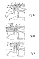
- Figure 1 and Figures 3a to c show in section a preferred embodiment of a plastic closure for plastic containers.
- the neck 2 of the container 5 has at its upper end a flange 8 designed as a flange with an edge web 6, the height of which corresponds exactly to the thickness (or the height) of the extension 7 of the sealing edge 1, so that the edge surface 3 of the extension 7 ( Closure flange) and the edge surface 4 of the edge web lie directly next to each other in a common plane.
- a bellows 16 adjoins the sealing edge 1, which enables the closure to be turned inside out.
- the bellows 16 merges into a pouring spout 12 which is provided with a screw thread onto which the screw cap 13 is screwed.
- the pouring opening is additionally secured by a sealing membrane 14.
- a tear ring 17 can also be seen, by means of which the pouring spout 12, which is connected to the sealing edge 1 via the bellows 16, can be pulled out of the neck 2.
- separating gap 15 ' Between the extension 7 and the edge web 6 there is a narrow separating gap 15 ', which is shown in FIG. 2a as a separating line 15 is shown. The width of this gap is matched to the liquid plastic material; Likewise, the separation gap 15 'can also run inclined in the section shown in FIG. 3a. Approach 7 and edge web 6 do not necessarily have to have right-angled corners.
- FIG. 3b also shows the welding element 9 and the anvil 11 serving as an abutment in cross section.
- the welding element 9 has the shape of a hollow cylinder, the diameter and wall thickness of which are selected such that the welding surface has the edge surfaces 3 and 4 largely on both sides of the separation gap 15 'over the entire circumference of the closure, but not completely covered.
- the heating winding 17 is also shown in cross section.
- Figure 3b shows the closure immediately before the welding process.
- the sonotrode 9 is lowered onto the edge surfaces 3 and 4, the shoulder 7 of the sealing edge 1, assumed here to have a lower melting point, begins to flow, the contact with the sonotrode 9 becoming worse and further heating the liquid is avoided.
- the contact between the sonotrode 9 and the edge web 6 is maintained, so that this too is heated to its melting temperature and finally mixes in the liquid state with the liquid plastic material of the attachment 7.
- the weld seam 10 formed in this way can be seen in FIG. 3c.
- the sealing edge 1 is absolutely liquid-tight and firmly connected to the neck 2 of the container 5 via the edge web 6.
- the strength of the weld 10 corresponds to the strength of the closure or container material itself.
- FIG. 4a A further embodiment of a container neck and the associated closure is shown in cross section in FIG. 4a. Only the sealing edge 1 is visible from the closure.
- the neck 2 of the container 5 runs conically, as does the sealing edge 1 of the closure.
- This embodiment is particularly simple to manufacture and saves material.
- the conical shape of the neck 2 provides the sealing edge 1 with a sufficiently firm fit. Any protruding material in the area of the edge surfaces can be melted away by the welding element 9.
- FIGS. 4b and 4c represent the closure immediately before and after welding, analogously to FIGS. 3b and 3c. In this case, the separating gap 15 'does not otherwise run perpendicularly but rather at a slight angle to the welding plane.
- FIG. 5a shows a further embodiment in cross-section analogous to FIG. 4a, in which the neck 2 also has a very simple shape.
- the sealing edge 1 also has an attachment 7 here, which rests on the edge 8 of the neck 2, so that the side edge surfaces 3 'and 4' of the attachment 7 and the neck 2 are produced as adjacent welding surfaces. Accordingly, the welding element 9 'is fed laterally. In this case, however, welding with a single welding operation is difficult because the concentric feeding of a plurality of welding elements 9 ', which in this embodiment are circular arc in plan view, is practically not feasible.
- circular arc-shaped welding elements 9 'in plan view can be applied two or more times.
- FIGS. 5b and 5c in turn show the area of the weld shortly before and after welding.
- FIG. 2b shows the top view of a weld in an embodiment according to FIGS. 1 and 3a to c.
- the weld seam 10 reveals a certain pattern which results from the impression of the sonotrode welding surface, which is generally provided with a certain pattern or a roughening in order to achieve better heat generation.
- the method can also be carried out with a completely smooth welding surface, in particular if the welding element is not a sonotrode but a welding element which heats in a conventional manner.
Landscapes
- Engineering & Computer Science (AREA)
- Mechanical Engineering (AREA)
- Physics & Mathematics (AREA)
- Thermal Sciences (AREA)
- High Energy & Nuclear Physics (AREA)
- Plasma & Fusion (AREA)
- Lining Or Joining Of Plastics Or The Like (AREA)
- Closures For Containers (AREA)
- Details Of Rigid Or Semi-Rigid Containers (AREA)
Abstract
Description
- Die Erfindung betrifft einen Kunststoffverschluß für einen Kunststoffbehälter, mit einem am Behälter angesetzten Hals, welcher aus einem Kunststoff anderer Härte oder Schmelztemperatur besteht als der Verschluß und in welchen ein Dichtungsrand des Verschlusses eingesetzt ist.
- Derartige Behälterverschlüsse sind bekannt und werden in im allgemeinen zylindrische, stutzenförmige Hälse von Kunststoffbehältern mit mehr oder weniger grober Passung eingesetzt. Bekannt sind diese Verschlüsse vor allem von Kunststoffkanistern für Motoröl aber auch von Behältern für andere Flüssigkeiten wie Lebensmittel und Getränke (Speiseöl, Essig, Wein) oder flüssige Chemieprodukte.
- Da die Maßhaltigkeit der Hälse von Kunststoffkanistern nicht sehr gut ist und überdies produktionsbedingte Schwankungen und Unregelmäßigkeiten in der Form dieser Hälse auftreten, ist die flüssigkeitsdichte Befestigung eines Kunststoffverschlusses in einem solchen Behälterhals nur durch eine vergleichsweise aufwendige Verschlußkonstruktion möglich. Üblicherweise ragt ein Dichtungsrand, der an seiner Außenseite ringförmig mit einer Reihe paralleler Lamellen versehen ist, tief in den Behälterhals hinein, wobei eine oder mehrere der Lamellen mehr oder weniger zufällig an der Innenwand des Behälterhalses anliegen und so für die Abdichtung sorgen. Unterhalb der Lamellen ist am Dichtungsrand häufig noch ein Steg oder Nocken ebenfalls ringförmig angesetzt, die unter dem Hals in dem Behälter eingreifen und so den Verschluß im Behälter verankern sollen.
- Häufig sind diese Verschlüsse auch mit einem Balg versehen, der am Dichtungsrand ansetzt und mit seinem anderen Ende in eine Ausgießöffnung übergeht. Sofern das Material des Verschlusses genügend verformbar ist, kann die Ausgießöffnung, deren Durchmesser kleiner ist als der Durchmesser des Dichtungsrandes, unter Verformung des Balges in den Behälterhals eingedrückt werden, so daß die Ausgießöffnung nicht über den oberen Rand des Behälterhalses hinausragt. Mit Hilfe eines am oberen Ende der Ausgießöffnung angebrachten Reißringes kann die Ausgießöffnung bei Bedarf aus dem Hals herausgezogen werden.
- Die vorgenannten Verschlüsse weisen teilweise erhebliche Nachteile auf. So ist es z.B. möglich, mit Hilfe eines Werkzeuges, wie eines Schraubensziehers, den aus mehr oder weniger elastischem Kunststoffmaterial bestehenden Behälterverschluß herauszuhebeln, indem das Werkzeug zwischen den Behälterhals und den Dichtungsrand eingeführt wird. Da bei dieser Entfernung des Behälterverschlusses gewöhnlich keine Spuren zurückbleiben und der Behälterverschluß auch wieder in den Behälterhals eingesetzt werden kann, eignen sich derartige Behälterverschlüsse für einen mißbräuchlichen Austausch oder Versatz des Behälterinhaltes. Weiterhin ist die Dichtheit des Verschlusses nur zur gewährleisten, wenn der Behälterhals mit einer vergleichsweise hohen Präzision hergestellt wird, weshalb besonders einfache Verfahren u.U. nicht zum Einsatz kommen. Ebenso wird für den weit in den Behälter hineinragenden Dichtungsrand, die Lamellen und den Befestigungssteg bzw. die Befestigungsnocken relativ viel Material verbraucht. Außerdem erfordert die Formgebung für den Dichtungsrand und die angesetzten Dichtungs- und Befestigungselemente einen relativ hohen apparativen Aufwand, so daß auch hierin ein wesentlicher Kostenfaktor zu sehen ist.
- Demnach besteht die der Erfindung zugrundeliegende Aufgabe darin, einen Kunststoffverschluß für Kunststoffbehälter zu schaffen, dessen Herstellung einen geringen apparativen Aufwand erfordert, der eine einfachere Herstellung des Behälterhalses erlaubt, weniger Material erfordert, sicher am Behälterhals zu befestigen ist und ohne Beschädigung des Verschlusses oder des Behälters nicht vom Behälter getrennt werden kann.
- Diese Aufgabe wird dadurch gelöst, daß eine Randfläche des Dichtungsrandes im wesentlichen unmittelbar neben einer Randfläche des Halses verläuft und daß der Dichtungsrand durch gleichzeitiges Erhitzen der nebeneinanderliegenden Randflächen mit dem Hals verschweißt ist.
- Dabei liegen die erwähnten Randflächen vor dem Verschweißen vorzugsweise in einer Ebene nebeinander, so daß sie von einem Schweißwerkzeug mit ebener Schweißfläche leicht gleichzeitig erfaßt werden könne.
- Die Randflächen können jedoch auch in einem weitgehend beliebigen Winkel zueinander stehen, solange sie nur von einem geeignet geformten Schweißwerkzeug gleichzeitig erhitzt werden und die beiden unterschiedlichen, flüssigen Kunststoffe dabei ineinanderfließen können. Das Ineinanderfließen wird unter Umständen dadurch erleichtert, daß zwischen den beiden miteinander zu verschweißenden Teilen ein Trennspalt von geeigneter Breite vorgesehen ist.
- Der Begriff "gleichzeitiges Erhitzen" ist dabei so zu verstehen, daß die beiden miteinander zu verschweißenden Kunststoffe möglichst gleichzeitig ihre jeweilige Schmelztemperatur erreichen und somit im Augenblick ihrer Verflüssigung augenblicklich ineinanderfließen können. Dazu kann es erforderlich sein, mit dem Erhitzen des höher schmelzenden Kunststoffes etwas eher zu beginnen als mit dem Erhitzen des niedriger schmelzenden Kunststoffes oder aber bei gleichzeitigem Beginn des Erhitzungsvorganges dem höher schmelzenden Kunststoff mehr Wärmeenergie zuzuführen als dem niedriger schmelzenden Kunststoff.
- Die zuerst genannte Möglichkeit kann man leicht verwirklichen, indem man die beiden Randflächen zwar parallel zu einander jedoch nicht in einer gemeinsamen Ebene sondern etwas versetzt gegeinander anordnet, so daß die Randfläche des höher schmelzenden Kunststoffes gegenüber der Randfläche des niedriger schmelzenden Kunststoffes etwas übersteht und mit der ebenen Schweißfläche eines Schweißwerkzeuges entsprechend eher in Berührung kommt.
- Das Verfahren wird im einzelnen später erläutert.
- Die Verschweißung des Verschlusses mit dem Behälterhals ist in mehrfacher Hinsicht vorteilhaft. So ist die Maßhaltigkeit des Behälterhalses und auch des Dichtungsrandes des Verschlusses von untergeordneter Bedeutung, solange nur die zu verschweißenden Teile dicht genug beieinanderliegen, was mit den konventionellen Mitteln der Massenfertigungstechnik ohne weiteres erreichbar ist. Weiterhin entfällt der relativ hohe Aufwand für die Formgebung des Dichtungsrandes mit anhängenden Lamellen und Befestigungselementen. Außerdem ist die Schweißnaht absolut flüssigkeitsdicht und der Verschluß läßt sich ohne erkennbare Beschädigungen nicht vom Behälter trennen.
- Eine kostengünstige und Material sparende Herstellungsweise ist insofern von besonderem Vorteil, als es sich bei derartigen Verschlüssen um ein Massenprodukt handelt, das in sehr großen Stückzahlen hergestellt und an die entsprechenden Behälter angebracht wird. Erfindungsgemäß ist daher vorgesehen, daß der Hals des Behälters und der Dichtungsrand des Verschlusses im wesentlichen zylindrisch sind, was ihre Herstellung und Handhabung ebenfalls erleichtert.
- Bei einem Kunststoffverschluß nach der Erfindung ist weiterhin vorgesehen, daß der Dichtungsrand einen überstehenden Verschlußflansch aufweist und auf dem Halsrand aufliegt. Auf diese Weise erreicht man, daß nach dem Einsetzen des Verschlusses in die Öffnung des Behälterhalses der Verschluß in seiner Position im wesentlichen fixiert ist, so daß die Verschweißung der dadurch korrekt positionierten Teile ohne weitere Justierung des Verschlusses erfolgen kann.
- Besonders vorteilhaft ist es dabei, wenn bei einem Verschluß gemäß der Erfindung der Halsrand als Flansch mit hochstehendem Randsteg ausgebildet ist, dessen Höhe der Dicke des Verschlußflansches und dessen innere Abmessungen kleiner als die äüßeren Abmessungen des Verschlußflansches sind. Im Falle eines zylindrischen Verschlusses bedeutet dieses, daß der am Dichtungsrand des Verschlusses befindliche ringförmige Verschlußflansch auf dem als Flansch ausgebildeten Rand des Behälterhalses aufliegt, wobei der Verschlußflansch ebenfalls ringförmig von dem am Flansch angesetzten Randsteg mit Passung umschlossen wird. Gleichzeitig ist die Höhe dieses Randsteges so bemessen, daß seine Oberkante mit der oberen Kante des Verschlußflansches abschließt, so daß seine dem Behälter abgewandte Oberfläche unmittelbar neben der dem Behälter abgewandten Oberfläche des Verschlußflansches und zusammen mit dieser in einer gemeinsamen Ebene liegt.
- Eine derartige Ausbilding des Verschlusses und des Halsrandes ermöglicht einen besonders einfachen und sicheren Zugang entsprechender Schweißvorrichtungen.
- Hinsichtlich des Verfahrens zur Herstellung eines Kunststoffverschlusses für einen Kunststoffbehälter, welcher aus einem Kunststoff anderer Härte oder Schmelztemperatur besteht als der Verschluß, mit einem am Behälter angesetzten Hals, in welchen ein Dichtungsrand des Verschlusses eingesetzt ist, wird die der Erfindung zugrundeliegende Aufgabe dadurch gelöst, daß gleichzeitig zumindest ein Teil der nebeneinanderliegenden Randfläche des Dichtungsrandes und der Randfläche des Halses auf eine Temperatur etwas oberhalb der Schmelztemperatur des jeweiligen Kunststoffes erhitzt wird.
- Durch das gleichzeitige Erhitzen der beiden Kunststoffe von unterschiedlicher Härte und/oder Schmelztemperatur erreicht man, daß beide Kunststoffe flüssig werden, ineinanderfließen und so eine feste und dichte Schweißnaht bilden. Zwar sind Verfahren bekannt, bei denen Kunststoffteile durch gleichzeitiges Erhitzen beider Teile miteinander verschweißt werden, jedoch handelt es sich dabei ausschließlich um die Verschweißung von Kunststoffmaterialien, die im wesentlichen jeweils die gleiche Härte und Schmelztemperatur aufweisen. Weiterhin sind Verfahren bekannt, bei denen Kunststoffe unterschiedlicher Schmelztemperatur dadurch miteinander verbunden werden, daß der niedrigere schmelzende Kunststoff verflüssigt wird und dadurch mit dem fest bleibenden, höher schmelzenden Kunststoff verklebt. Eine derartige Klebeverbindung ist jedoch nicht sehr fest und kann sich beispielsweise schon allein durch das Ziehen an einem Reißring bei der oben beschriebenen gängigen Ausführungsform lösen.
- Weiterhin ist bei dem Verfahren gemäß der Erfindung vorgesehen, daß die nebeneinanderliegenden Randflächen des Dichtungsrandes und des Halses beiderseits ihrer Trennlinie auf ihrer ganzen Länge gleichzeitig auf eine Temperatur etwas oberhalb der Schmelztemperatur des jeweiligen Kunststoffes erhitzt werden.
- Auf diese Weise erreicht man mit einem einzigen kurzen Schweißvorgang eine vollständige Abdichtung und Befestigung des Verschlusses am Behälter.
- Hinsichtlich der Vorrichtung zur Durchführung des erwähnten Verfahrens wird die der Erfindung zugrundeliegende Aufgabe dadurch gelöst, daß ein Schweißelement mindestens Schweißflächen aufweist, die parallel zu den zu verschweißenden Randflächen des Dichtungsrandes und des Halses verlaufen und mit diesen Flächen in Kontakt bringbar sind.
- Beim Kontakt der Fläche des Schweißelementes mit den Randflächen des Dichtungsrandes und des Halses werden diese erhitzt bis sie flüssig werden, ineinanderfließen und so die Schweißnaht bilden. Da die Fläche des Schweißelementes beide Randflächen gleichzeitig berührt, kann man davon ausgehen, daß zunächst der niedriger schmelzende Kunststoff zu fließen beginnt, dabei jedoch den Kontakt mit der heißen Schweißfläche verliert, solange das Schweißelement durch die Randfläche des noch festen höher schmelzenden Kunststoffteils abgestützt wird. Dadurch wird eine Überhitzung und Zersetzung des niedriger schmelzenden Kunststoffes vermieden. Sobald auch der höher schmelzende Kunststoff flüssig wird, fließen beide Kunststoffe ineinander und bilden die Schweißnaht.
- Je nach der Art, dem Fließverhalten und der Dichte der zu verbindenden Kunststoffe kann der vor dem Verschweißen entlang der Trennlinie verlaufende Spalt zwischen den zu verbindenden Kunststoffteilen unterschiedlich breit, tief und/oder geneigt verlaufen, so daß sich eine optimale Durchmischung der flüssigen Komponenten ergibt.
- Zur Herstellung einer möglichst sauberen und gleichmäßigen Schweißnaht ist erfindungsgemäß vorgesehen, daß als Widerlager für das auf die Randflächen gepreßte Schweißelement ein Amboß vorgesehen ist. Die Möglichkeit und die Art der Anbringung dieses Ambosses hängt dabei jedoch von der Form des Verschlusses und des Halses und von der Lage der Schweißnaht ab.
- Für die erfindungsgemäße Ausführungsform eines geschweißten Kunststoffbehälterverschlusses, bei welcher der Hals einen Flansch mit Randsteg und der Dichtungsrand einen Verschlußflansch bzw. einen Ansatz von der Höhe des Randsteges aufweisen, ist es zweckmäßig und vorteilhaft, wenn das Schweißelement die Form eines Hohlzylinders und der Amboß die Form eines geteilten Ringes hat.
- Dabei ist der Innendurchmesser des Hohlzylinders kleiner als der Außendurchmesser des ringförmigen Ansatzes, während der Außendurchmesser des Hohlzylinders größer ist als der Innendurchmesser des kreisförmigen Randsteges. Auf diese Weise ist gewährleistet, daß die Schweißfläche des Schweißelementes auf jeden Fall die nebeneinanderliegenden Randflächen des Ansatzes und des Randsteges beiderseits der Trennlinie bzw. des Trennspaltes erfaßt und eine vollständige, kreisringförmige Schweißnaht erzeugt.
- Weiterhin ist zweckmäßig, wenn gleichzeitig der Innendurchmesser des Hohlzylinders größer ist als der Innendurchmesser des Ansatzes, während der Außendurchmesser des Hohlzylinders kleiner ist als der Außendurchmesser des Randsteges. Durch diese Maßnahme ist nämlich sichergestellt, daß von den zu verschweißenden Kunststoffmaterialien innerhalb und/oder außerhalb des Hohlzylinders kleine Randbereiche erhalten bleiben, so daß der flüssige Kunststoff nicht seitlich abfließt.
- Ein weiteres erfindungsgemäßes Merkmal liegt darin, daß das Schweißelement durch eine Heizwicklung auf seinem äußeren Umfang heizbar ist.
- Die Wärmezufuhr von außen bewirkt einen Temperaturgradienten auf der Oberfläche des Schweißelementes in radialer Richtung. Auf diese Weise erhält beispielsweise der weiter außenliegende, höher schmelzende Randsteg des Halses eine höhere Wärmezufuhr als der niedriger schmelzende Ansatz im inneren Bereich der Schweißfläche, wodurch sich mit Vorteil eine schnellere Verflüssigung und Durchmischung beider Kunststoffe ergibt, so daß der Schweißvorgang insgesamt beschleunigt abläuft. Selbstverständlich kann eine entsprechende Heizwicklung auch im Inneren des Hohlzylinders oder eines anders geformten Schweißelementes angebracht werden, falls der höher schmelzende Kunststoff diesem Bereich näher liegen sollte.
- In einer besonders bevorzugten Ausführungsform der Erfindung ist vorgesehen, daß das Schweißelement eine Sonotrode (Ultraschallkopf) ist.
- Das Ultraschallschweißen ist an sich schon bekannt. Dabei überträgt ein Ultraschallkopf (Sonotrode) Ultraschallschwingungen auf das zu erwärmende bzw. zu verschweißende Objekt. Bei genügender Intensität der Ultraschallwellen wird durch inelastische Prozesse bzw. durch Reibung in den Übergangsbereichen in dem Kunststoff so viel Energie absorbiert und in Wärmeenergie umgesetzt, daß er zu schmelzen beginnt. Dabei haben die Ultraschallwellen den Vorteil, daß man sie mit einer gewissen Richtwirkung ausstrahlen und so auch ganz gezielt innere Bereiche des zu verschweißenden Kunststoffes erwärmen kann. Die Erwärmung erfolgt also nicht nur oberflächlich, sondern erfaßt gleichzeitig auch tiefere Bereiche, was ebenfalls zu einer Beschleunigung des Schweißvorganges beiträgt und darüberhinaus auch eine tiefere und bessere Schweißnaht ergibt.
- Die Wärmezufuhr wird dabei sehr schnell unterbrochen, wenn der Kunststoff aufgrund seiner Verflüssigung den Kontakt mit der Sonotrode verliert, so daß die dem Kunststoff zugeführte Wärmemenge durch die Verflüssigung sozusagen selbsttätig reguliert wird. Dabei kann das zusätzliche Aufprägen eines Temperaturgradienten, wie vorstehend beschrieben, ebenfalls vorteilhaft sein.
- Weitere Vorteile, Merkmale und Anwendungsgmöglichkeiten der vorliegenden Erfindung ergeben sich aus der nachfolgenden Beschreibung bevorzugter Ausführungsformen und den dazugehörigen Figuren.
- Es zeigen:
- Figur 1 einen Schnitt durch einen in einen Behälterhals eingesetzten Kunststoffverschluß in einer bevorzugten Ausführungsform,
- Figur 2a eine Ansicht auf Figur 1 von oben vor der Ver schweißung,
- Figur 2b eine Ansicht auf Figur 1 von oben nach der Verschweißung,
- Figur 3a einen Teilausschnitt aus Figur 1,
- Figuren 3b und c den gleichen Teilausschnitt wie Figur 3a kurz vor bzw. nach der Verschweißung,
- Figur 4a eine weitere Ausführungsform, wobei vom Verschluß nur der Dichtungsrand dargestellt ist,
- Figur 4b und c entsprechen den Figuren 3b und 3c für die Ausführungsform nach Figur 4a,
- Figuren 5a bis c eine weitere Ausführungsform analog zu den Figuren 4a bis c und
- Figur 6 eine Schweißvorrichtung in der bevorzugten Ausführungsform
- Figur 1 und die Figuren 3a bis c zeigen im Schnitt eine bevorzugte Ausführungsform eines Kunststoffverschlusses für Kunststoffbehälter.
- Der Hals 2 des Behälters 5 hat an seinem oberen Ende einen als Flansch ausgebildeten Halsrand 8 mit einem Randsteg 6, dessen Höhe gerade der Dicke (bzw. der Höhe) des Ansatzes 7 des Dichtungsrandes 1 entspricht, so daß die Randfläche 3 des Ansatzes 7 (Verschlußflansch) und die Randfläche 4 des Randsteges unmittelbar nebeneinander in einer gemeinsamen Ebene liegen. An den Dichtungsrand 1 schließt sich ein Balg 16 an, der ein Einstülpen des Verschlusses ermöglicht. An seinem anderen Ende geht der Balg 16 in eine Ausgießtülle 12 über, die mit einem Schraubgewinde versehen ist, auf das der Schraubverschluß 13 aufgeschraubt ist. Die Ausgießöffnung ist zusätzlich durch eine Siegelmembran 14 gesichert. In Figur 1 ist zusätzlich noch ein Reißring 17 zu erkennen, mit Hilfe dessen die über dem Balg 16 mit dem Dichtungsrand 1 verbundene Ausgießtülle 12 aus dem Hals 2 herausgezogen werden kann.
- Zwischen dem Ansatz 7 und dem Randsteg 6 befindet sich ein schmaler Trennspalt 15', der in Figur 2a als Trennlinie 15 dargestellt ist. Die Breite dieses Spaltes wird auf das flüssige Kunststoffmaterial abgestimmt; ebenso kann der Trennspalt 15' in dem in Figur 3a dargestellten Schnitt auch geneigt verlaufen. Ansatz 7 und Randsteg 6 müssen also nicht notwendigerweise rechtwinklige Ecken aufweisen.
- Die Figur 3b stellt zusätzlich zu dem Verschluß auch das Schweißelement 9 und den als Widerlager dienenden Amboß 11 im Querschnitt dar. Bei dieser Ausführungsform hat das Schweißelement 9 die Form eines Hohlzylinders, dessen Durchmesser und Wandstärke so gewählt sind, daß die Schweißfläche die Randflächen 3 und 4 beiderseits des Trennspalts 15' auf dem gesamten Umfang des Verschlusses weitgehend, jedoch nicht vollständig bedeckt.
- Zur Erzeugung eines Temperaturgradienten in radialer Richtung des Schweißelementes 9 ist auch die Heizwicklung 17 im Querschnitt dargestellt.
- Figur 3b stellt den Verschluß unmittelbar vor dem Schweißvorgang dar. Beim Absenken der Sonotrode 9 auf die Randflächen 3 und 4 beginnt der - hier als niedriger schmelzend angenommene - Ansatz 7 des Dichtungsrandes 1 zu zerfließen, wobei der Kontakt zur Sonotrode 9 schlechter und eine weitere Aufheizung der Flüssigkeit vermieden wird. Gleichzeitig bleibt jedoch der Kontakt zwischen Sonotrode 9 und Randsteg 6 erhalten, so daß auch dieser auf seine Schmelztemperatur erwärmt wird und sich schließlich im flüssigen Zustand mit dem flüssigen Kunststoffmaterial des Ansatzes 7 vermischt.
- Die so gebildete Schweißnaht 10 ist in Figur 3c zu erkennen. In diesem Zustand ist der Dichtungsrand 1 über den Randsteg 6 absolut flüssigkeitsdicht und fest mit dem Hals 2 des Behälters 5 verbunden. Die Festigkeit der Schweißnaht 10 entspricht dabei der Festigkeit des Verschluß- bzw. des Behältermaterials selbst.
- Die Herstellung des Dichtungsrandes 1 und damit des gesamten Verschlusses erfordert bei dieser Ausführungsform erheblich weniger Material als im Falle der bekannten Verschlüsse mit Dichtungslamellen und Befestigungselementen.
- In Figur 4a ist eine weitere Ausführungsform eines Behälterhalses und des zugehörigen Verschlusses im Querschnitt dargestellt. Dabei ist vom Verschluß nur der Dichtungsrand 1 sichtbar. Der Hals 2 des Behälters 5 verläuft bei dieser Ausführungsform konisch ebenso wie der Dichtungsrand 1 des Verschlusses. Diese Ausführungsform ist besonders einfach und materialsparend herzustellen. Der Dichtungsrand 1 erhält durch die konische Form des Halses 2 einen ausreichenden festen Sitz. Eventuell überstehendes Material im Bereich der Randflächen kann durch das Schweißelement 9 weggeschmolzen werden. Die Figuren 4b und 4c stellen analog zu den Figuren 3b und 3c den Verschluß unmittelbar vor und nach dem Verschweißen dar. In diesem Fall verläuft der Trennspalt 15' im übrigen nicht senkrecht sondern etwas geneigt zur Schweißebene.
- Die Figur 5a stellt analog zu Figur 4a eine weitere Ausführungsform im Querschnitt dar, bei welcher der Hals 2 ebenfalls eine sehr einfache Form hat. Der Dichtungsrand 1 weist auch hier einen Ansatz 7 auf, der auf dem Rand 8 des Halses 2 aufliegt, so daß sich als nebeneinanderliegende Schweißflächen die seitlichen Randflächen 3' und 4' des Ansatzes 7 bzw. des Halses 2 ergeben. Dementsprechend wird das Schweißelement 9' seitlich zugeführt. In diesem Fall ist jedoch das Schweißen mit einem einzigen Schweißvorgang nur schlecht möglich, da das konzentrische Zuführen mehrerer Schweißelemente 9', welche in dieser Ausführungsform in der Draufsicht kreisbogenförmig sind, praktisch nicht durchführbar ist. Zum Erzielen einer durchgehend umlaufenden Schweißnaht können beispielsweise kreuz- oder sternförmig gegenüberliegende, in der Draufsicht kreisbogenförmige Schweißelemente 9' zwei- oder mehrmals angesetzt werden.
- Die Figuren 5b und 5c stellen wiederum den Bereich der Schweißnaht kurz vor und nach dem Verschweißen dar. Die Figur 2b zeigt die Draufsicht auf eine Schweißnaht bei einer Ausführungsform gemäß den Figuren 1 und 3a bis c. Die Schweißnaht 10 läßt ein gewisses Muster erkennen, welches vom Abdruck der Sonotrodenschweißfläche herrührt, welche im allgemeinen mit einem gewissen Muster bzw. einer Aufrauhung versehen wird, um eine bessere Wärmeerzeugung zu erreichen. Das Verfahren ist jedoch auch mit einer völlig glatten Schweißfläche durchführbar, insbesondere wenn das Schweißelement keine Sonotrode sondern ein auf konventionelle Weise heizendes Schweißelement ist.
Claims (11)
Priority Applications (1)
| Application Number | Priority Date | Filing Date | Title |
|---|---|---|---|
| AT86109837T ATE49556T1 (de) | 1985-08-10 | 1986-07-17 | Geschweisster kunststoffverschluss fuer kunststoffbehaelter, verfahren zur herstellung desselben und vorrichtung zur durchfuehrung des verfahrens. |
Applications Claiming Priority (2)
| Application Number | Priority Date | Filing Date | Title |
|---|---|---|---|
| DE19853528815 DE3528815A1 (de) | 1985-08-10 | 1985-08-10 | Geschweisster kunststoffverschluss fuer kunststoffbehaelter, verfahren zur herstellung desselben und vorrichtung zur durchfuehrung des verfahrens |
| DE3528815 | 1985-08-10 |
Publications (2)
| Publication Number | Publication Date |
|---|---|
| EP0218023A1 true EP0218023A1 (de) | 1987-04-15 |
| EP0218023B1 EP0218023B1 (de) | 1990-01-17 |
Family
ID=6278268
Family Applications (1)
| Application Number | Title | Priority Date | Filing Date |
|---|---|---|---|
| EP19860109837 Expired - Lifetime EP0218023B1 (de) | 1985-08-10 | 1986-07-17 | Geschweisster Kunststoffverschluss für Kunststoffbehälter, Verfahren zur Herstellung desselben und Vorrichtung zur Durchführung des Verfahrens |
Country Status (5)
| Country | Link |
|---|---|
| US (1) | US4746025A (de) |
| EP (1) | EP0218023B1 (de) |
| JP (1) | JPS6290220A (de) |
| AT (1) | ATE49556T1 (de) |
| DE (2) | DE3528815A1 (de) |
Cited By (1)
| Publication number | Priority date | Publication date | Assignee | Title |
|---|---|---|---|---|
| EP0675051A3 (de) * | 1994-03-28 | 1996-03-27 | Berg Jacob Gmbh Co Kg | Schraubkappe mit Anschweissring. |
Families Citing this family (42)
| Publication number | Priority date | Publication date | Assignee | Title |
|---|---|---|---|---|
| US5060804A (en) * | 1991-03-25 | 1991-10-29 | International Paper Company | Gable top carton wrapper |
| DE4111758C2 (de) * | 1991-04-11 | 1996-10-17 | Tetra Pak Gmbh | Verfahren und Vorrichtung zum Verschließen einer Packung |
| JPH0547699U (ja) * | 1991-12-04 | 1993-06-25 | 日東電工株式会社 | プラスチック容器の接合構造 |
| US5256225A (en) * | 1992-01-13 | 1993-10-26 | Royal Packaging Industries Van Leer B.V. | Pail closure application method |
| JPH0572755U (ja) * | 1992-03-11 | 1993-10-05 | 凸版印刷株式会社 | 容器用口栓 |
| US5484527A (en) * | 1993-12-13 | 1996-01-16 | Stanadyne Automotive Corp. | Module for filter assembly base |
| US5431306A (en) * | 1993-12-31 | 1995-07-11 | Innovative Molding, Inc. | Drain back container with internal thread |
| GB2310201B (en) * | 1995-01-30 | 1999-04-14 | Portola Packaging Inc | Fitment in combination with a machine for inserting the fitment into a container wall |
| GB2327222B (en) * | 1995-01-30 | 1999-04-14 | Portola Packaging Inc | Fitment having removable membrane |
| US6464096B2 (en) | 1995-01-30 | 2002-10-15 | Portola Packaging, Inc. | Fitment having removable membrane |
| US5622579A (en) * | 1995-03-31 | 1997-04-22 | Graham Packaging Corporation | Method for attachment of a service device to a container |
| US5931324A (en) * | 1995-03-31 | 1999-08-03 | Graham Packaging Company, L.P. | Plastic container and non-integral handle |
| US5769277A (en) * | 1996-07-11 | 1998-06-23 | Aptargroup, Inc. | Dispensing closure having a force-directing removable seal |
| US5755360A (en) * | 1996-07-11 | 1998-05-26 | Aptargroup, Inc. | Multi-material, multi-shot, injection molded dispensing closure having a removable seal |
| US5918754A (en) * | 1996-08-07 | 1999-07-06 | Graham Packaging Corporation | Blow-molded plastic container with permanently attached separate handle |
| US5855544A (en) * | 1997-08-12 | 1999-01-05 | Technical Developers, Inc. | Flexible container with tubular fitment and method and apparatus for assembling same |
| AU1089199A (en) * | 1997-10-14 | 1999-05-03 | Technical Developers, Inc. | Flexible container with tubular fitment and method of mounting same |
| WO1999023002A2 (en) * | 1997-10-30 | 1999-05-14 | International Plastics And Equipment Corporation | Snap-on screw-off closure |
| DE19807768A1 (de) * | 1998-02-24 | 1999-08-26 | Bericap Gmbh & Co | Kunststoffdeckel mit Kunststoffverschluß |
| US5971232A (en) * | 1998-06-03 | 1999-10-26 | Aptargroup, Inc. | Dispensing structure which has a pressure-openable valve retained with folding elements |
| GB0205832D0 (en) * | 2002-03-13 | 2002-04-24 | Elopak Systems | Improvements in or relating to containers and methods of production thereof |
| RU2228845C1 (ru) * | 2002-11-26 | 2004-05-20 | ЗАО Медико-технологический холдинг "МТХ" | Способ соединения разнотолщинных деталей из полимерных материалов |
| GB2428669B (en) * | 2003-03-26 | 2007-08-15 | Portola Packaging Ltd | Closures and containers in combination therewith |
| DE502004012264D1 (de) * | 2003-07-30 | 2011-04-14 | Rm Beteiligungs Ag | Kunststoffgetränkeflasche mit kapsel |
| US7413097B1 (en) | 2003-08-01 | 2008-08-19 | Portola Packaging, Inc. | Tamper-evident closure and method of making same |
| ES2320677T3 (es) * | 2004-02-27 | 2009-05-27 | Mauser-Werke Gmbh | Contenedor paletizado. |
| USD530603S1 (en) | 2004-05-11 | 2006-10-24 | Portola Packaging, Inc. | Container closure having a pull tab |
| ES2264332B1 (es) * | 2004-07-08 | 2007-08-16 | Reyde, S.A. | Procedimiento de union de una valvula a la salida de un contenedor plastico y maquina que realiza dicho procedimiento. |
| JP2007253177A (ja) * | 2006-03-22 | 2007-10-04 | Denso Corp | 超音波接合方法、超音波接合装置および超音波接合された接合管 |
| DE102006049609A1 (de) * | 2006-10-20 | 2008-04-30 | Trw Automotive Electronics & Components Gmbh & Co. Kg | Verfahren zum Abdichten einer Öffnung in einem Bauteil |
| DE102008037103B4 (de) * | 2008-08-08 | 2012-03-01 | Sumitomo (Shi) Demag Plastics Machinery Gmbh | Plastifizierungs- und Einspritzvorrichtung für eine Spritzgießmaschine |
| EP2314444A1 (de) * | 2009-10-23 | 2011-04-27 | Nestec S.A. | Verschluss |
| USD747201S1 (en) | 2013-09-18 | 2016-01-12 | Bericap | Closure |
| FR3015442B1 (fr) | 2013-12-24 | 2016-02-05 | Bericap | Dispositif de bouchage articule avec indicateur de premiere ouverture |
| GB2523202B (en) * | 2014-02-18 | 2017-09-06 | Petainer Large Container Ip Ltd | Plastic Aerosol Container |
| DE102014008611A1 (de) * | 2014-06-06 | 2015-12-17 | Kocher-Plastik Maschinenbau Gmbh | Behältnis |
| USD833278S1 (en) | 2014-09-03 | 2018-11-13 | Bericap | Closure for a container |
| EP2998103B1 (de) * | 2014-09-18 | 2019-02-27 | Tetra Laval Holdings & Finance S.A. | Einheit und Verfahren zum Aufbringen von vorgeformten Öffnungsvorrichtungen auf einer Bahn aus Verpackungsmaterial |
| DE102015010477A1 (de) * | 2015-08-14 | 2017-02-16 | Unipress Etiketten & Schilder e.K. | Getränkedose aus Kunststoff |
| EP3854720B1 (de) | 2018-10-19 | 2024-08-28 | Toppan Printing Co., Ltd. | Tubenförmiger behälter und verfahren zur herstellung davon |
| JP7262900B2 (ja) * | 2019-05-31 | 2023-04-24 | 株式会社吉野工業所 | 付け替え式容器 |
| WO2021042018A1 (en) * | 2019-08-29 | 2021-03-04 | Rieke Llc | Child resistant closure and spout combination |
Citations (6)
| Publication number | Priority date | Publication date | Assignee | Title |
|---|---|---|---|---|
| US3263724A (en) * | 1964-07-27 | 1966-08-02 | Mojonnier Inc Albert | Container cap finish and cap |
| DE1536085A1 (de) * | 1966-10-05 | 1969-12-11 | Hesser Ag Maschf | Verpackungsbehaelter aus Kunststoffolien und Vorrichtung zu seiner Herstellung |
| FR2088530A3 (de) * | 1970-05-13 | 1972-01-07 | Stolz Heinrich | |
| DE7219898U (de) * | 1972-08-31 | Mauser Kg | Verschlussausführung für Kanister | |
| GB1469043A (en) * | 1974-02-26 | 1977-03-30 | American Hospital Supply Corp | Medical liquid bottle having a fused closure structure |
| EP0079816A1 (de) * | 1981-11-06 | 1983-05-25 | Aquifrance Plastique | Dose mit hermetischem Verschluss als Behälter für unterschiedliche Produkte |
Family Cites Families (6)
| Publication number | Priority date | Publication date | Assignee | Title |
|---|---|---|---|---|
| DE1022155B (de) * | 1953-03-26 | 1958-01-02 | Pelikan Werke Wagner Guenther | Luftdicht verschliessbarer Behaelter aus Kunststoff |
| US3402873A (en) * | 1964-11-09 | 1968-09-24 | Illinois Tool Works | Heat-sealed article and method |
| US3561668A (en) * | 1966-08-23 | 1971-02-09 | Anderson Bros Mfg Co | Sealed package |
| US3483066A (en) * | 1967-01-06 | 1969-12-09 | Branson Instr | Ultrasonic tool with fixturing means |
| CH537267A (de) * | 1970-12-10 | 1973-05-31 | Kapsch Telephon Telegraph | Verfahren und Vorrichtung zum dichten Verbinden eines Behältermantels aus thermoplastischem Kunststoff mit einem Boden- oder Deckelteil aus thermoplastischem Kunststoff mittels Ultraschall |
| US4411720A (en) * | 1982-03-22 | 1983-10-25 | Branson Ultrasonics Corporation | Ultrasonic welding method for sealing a thermoplastic cap to the neck of a thermoplastic container |
-
1985
- 1985-08-10 DE DE19853528815 patent/DE3528815A1/de not_active Withdrawn
-
1986
- 1986-07-17 DE DE8686109837T patent/DE3668300D1/de not_active Expired - Lifetime
- 1986-07-17 EP EP19860109837 patent/EP0218023B1/de not_active Expired - Lifetime
- 1986-07-17 AT AT86109837T patent/ATE49556T1/de not_active IP Right Cessation
- 1986-08-08 JP JP61185378A patent/JPS6290220A/ja active Pending
- 1986-08-08 US US06/894,661 patent/US4746025A/en not_active Expired - Fee Related
Patent Citations (6)
| Publication number | Priority date | Publication date | Assignee | Title |
|---|---|---|---|---|
| DE7219898U (de) * | 1972-08-31 | Mauser Kg | Verschlussausführung für Kanister | |
| US3263724A (en) * | 1964-07-27 | 1966-08-02 | Mojonnier Inc Albert | Container cap finish and cap |
| DE1536085A1 (de) * | 1966-10-05 | 1969-12-11 | Hesser Ag Maschf | Verpackungsbehaelter aus Kunststoffolien und Vorrichtung zu seiner Herstellung |
| FR2088530A3 (de) * | 1970-05-13 | 1972-01-07 | Stolz Heinrich | |
| GB1469043A (en) * | 1974-02-26 | 1977-03-30 | American Hospital Supply Corp | Medical liquid bottle having a fused closure structure |
| EP0079816A1 (de) * | 1981-11-06 | 1983-05-25 | Aquifrance Plastique | Dose mit hermetischem Verschluss als Behälter für unterschiedliche Produkte |
Cited By (1)
| Publication number | Priority date | Publication date | Assignee | Title |
|---|---|---|---|---|
| EP0675051A3 (de) * | 1994-03-28 | 1996-03-27 | Berg Jacob Gmbh Co Kg | Schraubkappe mit Anschweissring. |
Also Published As
| Publication number | Publication date |
|---|---|
| ATE49556T1 (de) | 1990-02-15 |
| JPS6290220A (ja) | 1987-04-24 |
| US4746025A (en) | 1988-05-24 |
| EP0218023B1 (de) | 1990-01-17 |
| DE3668300D1 (de) | 1990-02-22 |
| DE3528815A1 (de) | 1987-02-12 |
Similar Documents
| Publication | Publication Date | Title |
|---|---|---|
| EP0218023B1 (de) | Geschweisster Kunststoffverschluss für Kunststoffbehälter, Verfahren zur Herstellung desselben und Vorrichtung zur Durchführung des Verfahrens | |
| DE69201671T2 (de) | Abdichtaufsätze für Filterelemente. | |
| DE69811515T2 (de) | Metallkapsel mit kunstoffeinlage | |
| EP0842733B1 (de) | Verfahren zur Anbringung eines Funktionselementes, Funktionselement, Zusammenbauteil und Matrize | |
| DE1452782A1 (de) | Verfahren und Vorrichtung zum nietlosen Verbinden zweier duktiler Blechteile | |
| DE845263C (de) | Verfahren zum Verschweissen von Polyaethylen und aehnlichem plastischen Material | |
| DE3422546C2 (de) | Behälter-Verschlußkappe | |
| EP0129102B1 (de) | Behälterdeckel mit Öffnungseinrichtung | |
| EP2655202B1 (de) | Ausgiesser, verfahren zum herstellen eines ausgiessers und behälter umfassend einen derartigen ausgiesser | |
| EP0114398A2 (de) | Zusammendrückbarer Laminattubenbehälter | |
| DE3336908A1 (de) | Originalitaetsverschluss aus kunststoff | |
| WO2000002779A1 (de) | Verfahren zum anbringen eines schulterstücks an einem beutel | |
| DE19514072C2 (de) | Behälter und Verfahren zu dessen Herstellung | |
| DE2826680C2 (de) | Zusammendrückbarer Spendbehälter und Verfahren zu seiner Herstellung | |
| DE2919395A1 (de) | Verfahren und vorrichtung zur herstellung eines leicht zu oeffnenden behaelterverschlussteiles | |
| EP3448770B1 (de) | Schraubverschluss für grossbehälter | |
| DE60304556T2 (de) | Kunststoffkappe und herstellungsverfahren dafür | |
| DE3233806C2 (de) | ||
| DE2356796A1 (de) | Hohlkoerper und verfahren zu dessen herstellung | |
| DE69002499T3 (de) | Verpackung, insbesondere für unter Druck stehende Flüssigkeiten. | |
| DE3526682C2 (de) | ||
| DE1943349B2 (de) | Sicherungsring für Flaschen oder ähnliche Behälter sowie Verfahren zu deren Sicherung | |
| DE2512882B2 (de) | Verfahren zum Verschließen eines Behälters mit einer Folie aus thermoplastischem Kunststoff | |
| DE4125468C1 (de) | ||
| DE4207841C2 (de) | Stopfen für einen Behälter und Verfahren zur Herstellung des Stopfens |
Legal Events
| Date | Code | Title | Description |
|---|---|---|---|
| PUAI | Public reference made under article 153(3) epc to a published international application that has entered the european phase |
Free format text: ORIGINAL CODE: 0009012 |
|
| AK | Designated contracting states |
Kind code of ref document: A1 Designated state(s): AT DE FR GB IT NL SE |
|
| 17P | Request for examination filed |
Effective date: 19870506 |
|
| 17Q | First examination report despatched |
Effective date: 19871223 |
|
| ITF | It: translation for a ep patent filed | ||
| GRAA | (expected) grant |
Free format text: ORIGINAL CODE: 0009210 |
|
| AK | Designated contracting states |
Kind code of ref document: B1 Designated state(s): AT DE FR GB IT NL SE |
|
| PG25 | Lapsed in a contracting state [announced via postgrant information from national office to epo] |
Ref country code: SE Effective date: 19900117 |
|
| REF | Corresponds to: |
Ref document number: 49556 Country of ref document: AT Date of ref document: 19900215 Kind code of ref document: T |
|
| GBT | Gb: translation of ep patent filed (gb section 77(6)(a)/1977) | ||
| REF | Corresponds to: |
Ref document number: 3668300 Country of ref document: DE Date of ref document: 19900222 |
|
| ET | Fr: translation filed | ||
| PGFP | Annual fee paid to national office [announced via postgrant information from national office to epo] |
Ref country code: FR Payment date: 19900615 Year of fee payment: 5 |
|
| PGFP | Annual fee paid to national office [announced via postgrant information from national office to epo] |
Ref country code: GB Payment date: 19900618 Year of fee payment: 5 |
|
| PG25 | Lapsed in a contracting state [announced via postgrant information from national office to epo] |
Ref country code: AT Effective date: 19900717 |
|
| ITTA | It: last paid annual fee | ||
| PGFP | Annual fee paid to national office [announced via postgrant information from national office to epo] |
Ref country code: DE Payment date: 19900823 Year of fee payment: 5 |
|
| PLBE | No opposition filed within time limit |
Free format text: ORIGINAL CODE: 0009261 |
|
| STAA | Information on the status of an ep patent application or granted ep patent |
Free format text: STATUS: NO OPPOSITION FILED WITHIN TIME LIMIT |
|
| 26N | No opposition filed | ||
| PG25 | Lapsed in a contracting state [announced via postgrant information from national office to epo] |
Ref country code: NL Effective date: 19910201 |
|
| NLV4 | Nl: lapsed or anulled due to non-payment of the annual fee | ||
| PG25 | Lapsed in a contracting state [announced via postgrant information from national office to epo] |
Ref country code: GB Effective date: 19910717 |
|
| GBPC | Gb: european patent ceased through non-payment of renewal fee | ||
| PG25 | Lapsed in a contracting state [announced via postgrant information from national office to epo] |
Ref country code: FR Effective date: 19920331 |
|
| PG25 | Lapsed in a contracting state [announced via postgrant information from national office to epo] |
Ref country code: DE Effective date: 19920401 |
|
| REG | Reference to a national code |
Ref country code: FR Ref legal event code: ST |
|
| PG25 | Lapsed in a contracting state [announced via postgrant information from national office to epo] |
Ref country code: IT Free format text: LAPSE BECAUSE OF NON-PAYMENT OF DUE FEES;WARNING: LAPSES OF ITALIAN PATENTS WITH EFFECTIVE DATE BEFORE 2007 MAY HAVE OCCURRED AT ANY TIME BEFORE 2007. THE CORRECT EFFECTIVE DATE MAY BE DIFFERENT FROM THE ONE RECORDED. Effective date: 20050717 |