EP0219964B1 - Verfahren zur Herstellung von Kohlenstoffasern und diese Kohlenstoffasern - Google Patents
Verfahren zur Herstellung von Kohlenstoffasern und diese Kohlenstoffasern Download PDFInfo
- Publication number
- EP0219964B1 EP0219964B1 EP86306936A EP86306936A EP0219964B1 EP 0219964 B1 EP0219964 B1 EP 0219964B1 EP 86306936 A EP86306936 A EP 86306936A EP 86306936 A EP86306936 A EP 86306936A EP 0219964 B1 EP0219964 B1 EP 0219964B1
- Authority
- EP
- European Patent Office
- Prior art keywords
- fiber
- spinneret
- cross
- section
- lobe
- Prior art date
- Legal status (The legal status is an assumption and is not a legal conclusion. Google has not performed a legal analysis and makes no representation as to the accuracy of the status listed.)
- Expired
Links
Images






Classifications
-
- D—TEXTILES; PAPER
- D01—NATURAL OR MAN-MADE THREADS OR FIBRES; SPINNING
- D01F—CHEMICAL FEATURES IN THE MANUFACTURE OF ARTIFICIAL FILAMENTS, THREADS, FIBRES, BRISTLES OR RIBBONS; APPARATUS SPECIALLY ADAPTED FOR THE MANUFACTURE OF CARBON FILAMENTS
- D01F9/00—Artificial filaments or the like of other substances; Manufacture thereof; Apparatus specially adapted for the manufacture of carbon filaments
- D01F9/08—Artificial filaments or the like of other substances; Manufacture thereof; Apparatus specially adapted for the manufacture of carbon filaments of inorganic material
- D01F9/12—Carbon filaments; Apparatus specially adapted for the manufacture thereof
- D01F9/14—Carbon filaments; Apparatus specially adapted for the manufacture thereof by decomposition of organic filaments
-
- D—TEXTILES; PAPER
- D01—NATURAL OR MAN-MADE THREADS OR FIBRES; SPINNING
- D01D—MECHANICAL METHODS OR APPARATUS IN THE MANUFACTURE OF ARTIFICIAL FILAMENTS, THREADS, FIBRES, BRISTLES OR RIBBONS
- D01D5/00—Formation of filaments, threads, or the like
- D01D5/253—Formation of filaments, threads, or the like with a non-circular cross section; Spinnerette packs therefor
-
- D—TEXTILES; PAPER
- D01—NATURAL OR MAN-MADE THREADS OR FIBRES; SPINNING
- D01F—CHEMICAL FEATURES IN THE MANUFACTURE OF ARTIFICIAL FILAMENTS, THREADS, FIBRES, BRISTLES OR RIBBONS; APPARATUS SPECIALLY ADAPTED FOR THE MANUFACTURE OF CARBON FILAMENTS
- D01F9/00—Artificial filaments or the like of other substances; Manufacture thereof; Apparatus specially adapted for the manufacture of carbon filaments
- D01F9/08—Artificial filaments or the like of other substances; Manufacture thereof; Apparatus specially adapted for the manufacture of carbon filaments of inorganic material
- D01F9/12—Carbon filaments; Apparatus specially adapted for the manufacture thereof
- D01F9/14—Carbon filaments; Apparatus specially adapted for the manufacture thereof by decomposition of organic filaments
- D01F9/20—Carbon filaments; Apparatus specially adapted for the manufacture thereof by decomposition of organic filaments from polyaddition, polycondensation or polymerisation products
- D01F9/21—Carbon filaments; Apparatus specially adapted for the manufacture thereof by decomposition of organic filaments from polyaddition, polycondensation or polymerisation products from macromolecular compounds obtained by reactions only involving carbon-to-carbon unsaturated bonds
- D01F9/22—Carbon filaments; Apparatus specially adapted for the manufacture thereof by decomposition of organic filaments from polyaddition, polycondensation or polymerisation products from macromolecular compounds obtained by reactions only involving carbon-to-carbon unsaturated bonds from polyacrylonitriles
-
- D—TEXTILES; PAPER
- D01—NATURAL OR MAN-MADE THREADS OR FIBRES; SPINNING
- D01F—CHEMICAL FEATURES IN THE MANUFACTURE OF ARTIFICIAL FILAMENTS, THREADS, FIBRES, BRISTLES OR RIBBONS; APPARATUS SPECIALLY ADAPTED FOR THE MANUFACTURE OF CARBON FILAMENTS
- D01F9/00—Artificial filaments or the like of other substances; Manufacture thereof; Apparatus specially adapted for the manufacture of carbon filaments
- D01F9/08—Artificial filaments or the like of other substances; Manufacture thereof; Apparatus specially adapted for the manufacture of carbon filaments of inorganic material
- D01F9/12—Carbon filaments; Apparatus specially adapted for the manufacture thereof
- D01F9/14—Carbon filaments; Apparatus specially adapted for the manufacture thereof by decomposition of organic filaments
- D01F9/32—Apparatus therefor
Definitions
- This invention relates to a method for producing carbon fibers, and carbon fibers themselves.
- Carbon/graphite (C/G) fibers exhibit such high strength and light weight mechanical properties.
- the mechanical properties of C/G fibers depend upon how well their structure resembles the anisotropic structure of an ideal, i.e., perfect, graphite crystal.
- the three dimensional lattice structure of an ideal graphite crystal is basically a network of hexagonal crystal planes stacked one on top of the other with an orientation such that within each layer, covalent carbon-carbon bonds link individual graphite crystals together in the plane. These strong bonds give graphite its high strength characteristics in the direction parallel to these planes.
- Each layer of hexagonal crystal planes is perfectly parallel to its adjacent planes. Because these planes are perfectly parallel to one another, the interlayer spacing is very small, and consequently the ideal graphite crystal has a very high density.
- a perfect crystal has a theoretical tensile modulus of elasticity of 146 million pounds per square inch (msi), (1.01 TPa) and a theoretical ultimate tensile strength of 15 msi (0.103 TPa).
- C/G fibers differ from the perfect crystals of an ideal graphite lattice structure due to both surface and internal flaws and in the lesser amount of preferred orientation along the fiber axis, which is in the direction parallel to the hexagonal crystal planes.
- Structural flaws affect the ultimate tensile strength, and the degree of preferred orientation along the fiber axis affects the tensile modulus of elasticity.
- Carbon/graphite fibers have been produced from a number of different precursor materials.
- One such material is polyacrylonitrile (PAN), which is described as an atactic linear polymer whose fibril 3-D network tends to form an irregular helix structure as shown in Fig. 1.
- PAN polyacrylonitrile
- FIG. 1 A typical process for producing PAN-based C/G fibers is shown schematically in Fig. 1.
- the as-spun fiber is obtained by wet spinning PAN or its copolymers into a coagulation bath.
- the purpose of using a copolymerized precursor is to lower the glass transition temperature, thereby allowing the as-spun fiber to be stretched in liquids which boil at lower temperatures.
- the as-spun helical fiber is stretched to better orient the polymer molecules along the fiber axis. It is thought that oxidation of the stretched fiber maintains the preferred orientation along the fiber axis by cyclization of the nitrile groups as shown in Fig. 1. Suggested temperatures for oxidation are 220-270°C for up to seven hours.
- a further heat treatment step can be performed at temperatures between 1800 and 2500°C for less than one hour to purify and provide a higher degree of preferred orientation of the 3-D turbostratic structure.
- the modulus of elasticity of PAN-based C/G fiber increases with heat treatment temperature, but the tensile strength reaches a maximum value of approximately 450 ksi (3.10 GPa) at a temperature of approximately 1600°C.
- Surface flaws in the as-spun PAN-based fiber may be retained throughout the entire process and limit fiber strength. Internal flaws caused by voids left by rapidly evolving gases may occur during heat treatment and cause a decrease in tensile strength with higher temperatures. Moreover, the stretching required to obtain the desired strength characteristics is time-consuming and expensive in commercial production.
- a solution of PAN in a solvent such as dimethyl formamide is normally spun into a filament using either a "wet” solution spinning technique, as described above, or a “dry” solution spinning technique.
- the solvent In both wet and dry spinning, the solvent must diffuse through the filament and then evaporate into the spinning chamber (dry spinning) or enter the coagulating bath solution (wet spinning). If the rate of evaporation of the solvent (or the rate of loss of solvent into the coagulating bath) is less than the rate of diffusion of the solvent through the PAN filament, the filament will dry uniformly and the filament will have a circular cross-section.
- a PAN-based carbon fiber having a dogbone-shaped cross-section is observed to be lower in strength than PAN-based fibers of circular cross-section.
- PAN-based fibers having a trilobal cross-section are also observed to be weaker than PAN-based fibers of circular cross-section.
- the strength of PAN-based fiber of circular cross-section decreases with higher carbonizing temperature.
- dogbone-shaped PAN-based fiber becomes higher in strength with higher carbonizing temperature.
- Pitch whether natural in origin, such as coaltar or petroleum pitch, or synthetic in origin, such as specially prepared polyvinylchloride (PVC), has been used as a precursor for producing a melt spun C/G fiber.
- Pitch a graphitizable substance
- a graphitizable substance has been defined as one which fuses or becomes plastically deformed during heat treatment. According to this definition, rayonbased and PAN-based C/G fibers are not graphitizable. While they may set up in a turbostratic configuration, rayon and PAN are incapable of forming the characteristic three dimensional structure of graphite.
- graphite fibers are considered to be those fibers which have been heat-treated above 1700°C and have a carbon content of at least 99 percent.
- Carbon fibers are those fibers which have been heat-treated below 1700°C and have a carbon content of between 80 to 95 percent.
- the original material melts or fuses to form an isotropic pitch-like mass.
- spherical bodies begin to form.
- the spherical bodies are of an anisotropic liquid crystalline nature as viewed under polarized light. These spheres continue to grow and coalesce until a dense continuous anisotropic phase forms, which phase has been termed the "mesophase.”
- the mesophase is the intermediate phase of liquid crystalline region between the isotropic pitch and the semi-coke obtainable at higher temperatures.
- US-A-4,208,267 discloses a method for producing mesophase pitch-based C/G fibers in which a nearly 100 percent mesophase pitch precursor is melt spun. This method is illustrated schematically in Fig. 2.
- the nearly 100 percent mesophase precursor is prepared by converting a solvent-insoluble fraction of isotropic pitch into an anisotropic pitch containing between 75 and 100 percent mesophase by heating to between 230 to 400°C for less than ten minutes. For the most part, it is the large aromatics which convert to the mesophase upon heating.
- the solvent-insoluble fraction is pelletized as a solid and then melt spun through a conventional screw extruder at spin temperatures of between 360 and 370°C to produce a fiber filament of circular cross-section.
- Typical viscosities for the mesophase precursor at such spinning temperatures range between 200 and 700 poise (20 and 70 Pa s).
- the as-spun circular fibers produced from the mesophase were immediately subjected to carbonizing temperatures, the fibers would degrade and lose their anisotropic molecular orientation.
- the as-spun fibers are thermoset at 200 to 350°C in an oxygen atmosphere. After this oxidation step, carbonization/graphitization is accomplished in a horizontal graphite resistance furnace at temperatures between 1000 and 2000°C under a nitrogen atmosphere.
- non-circular synthetic fibers from melt spun polymers, such as polyester, nylon and polypropylene, for about 20 years.
- the extrusion process is identical to the one used to produce circular synthetic fibers, except that spinnerets with non-circular capillaries are used rather than ones with circular capillaries.
- Polymers have a relatively large range of temperatures over which the viscosity of the polymer is suitable for producing a melt spun fiber, whether circular or non-circular in cross-section.
- a polymer such as polystyrene shrinks during the draw-down process of melt spinning under typical commercial conditions, from a diameter of about 700 ⁇ m to a final diameter of about 40 ⁇ m over a distance of about 40 millimeters. This distance is sometimes referred to as the quench distance and is a critical parameter in obtaining a non-circular polymer fiber.
- anisotropic precursors such as mesophase pitch.
- anisotropic precursors have a surface tension between that of glass and that of polymers.
- quench distance for a circular carbon fiber produced from an anisotropic precursor is approximately 4 mm over which a 200 ⁇ m diameter is drawn down to a twelve micron diameter.
- the viscosity of an anisotropic precursor is far more temperature dependent than the viscosity of polymers.
- An object of the present invention is to provide a carbon fiber of improved tensile strength and modulus of elasticity over presently available carbon fibers.
- Another object of the present invention is to provide a method of producing carbon fibers having improved tensile strength characteristics and an improved modulus of elasticity over presently available carbon fibers.
- a method for producing a high elastic modulus, high tensile strength carbon fiber comprises: providing a molten precursor containing a substantial proportion of carbonaceous anisotropic material; maintaining the molten precursor at a temperature such that its viscosity falls within the range between 25 Pa.s (250 poise) and 200 Pa.s (2000 Poise) extruding the molten precursor through a spinneret defining a capillary having at least one lobe-shaped cross-sectional area; solidifying the extruded precursor as it emerges from the spinneret, into a fiber filament having a transverse cross-section substantially like the transverse cross-section of the capillary; rendering the fiber filament infusible; and thereafter heating the fiber filament in an inert environment at a temperature sufficient to substantially increase the tensile strength and the modulus of elasticity of the fiber filament.
- a carbon fiber having at least one lobe, each lobe in a transverse cross-section of the fiber having a microstructure emanating outwardly from a line extending along the length of the lobe.
- a method for producing a high elastic moldulus, high tensile strength carbon fiber comprises: providing a molten precursor containing a substantial proportion of carbonaceous anisotropic material; maintaining the molten precursor at a temperature such that its viscosity falls within the range between 25 Pa.s (250 poise) and 200 Pa.s (2000 poise); extruding the molten precursor through a spinneret defining a capillary having at least one lobe-shaped cross-sectional area; solidifying the extruded precursor as it emerges from the spinneret, into a fiber filament having a transverse cross-section substantially like the transverse cross-section of the capillary; rendering the fiber filament infusible; and thereafter heating the fiber filament in an inert environment at a temperature sufficient to substantially increase the tensile strength and modulus of elasticity of the fiber filament.
- a preferred embodiment of the method for producing a high elastic modulus, high tensile strength carbon fiber according to the present invention comprises providing a molten precursor containing a substantial proportion of carbonaceous anisotropic material.
- a suitable precursor material can be obtained according to the preparations disclosed in US-A-4,208,267 to Diefendorf et al, entitled, "Forming Optically Anisotropic Pitches,". Additional examples of suitable precursor materials are disclosed in each of US-A-4,017,327 and 4,026,788.
- Other pitch materials suitable for providing precursor material to be used in the method of the present invention include petroleum asphalt, coal tar pitch, and polyvinylchloride.
- the average bulk density of the mesophase pitch precursor pellets used in producing the conventional circular carbon fibers and the multilobal carbon fibers of the present invention was 0.48 g/cm3, and the melt density was 1.29 g/cm3.
- the ash content was found to be 0.0045 percent.
- the glass transition temperature was 244°C, while the melting temperature was about 280°C.
- the melt viscosity ranges from 1100 to 550 poise (110 - 55 Pa s) at the extremes of the spin window of 352 and 358°C, respectively. At the spin temperature of 344°C, the melt viscosity was 780 poise (78 Pa s).
- the method for producing a high elastic modulus, high tensile strength carbon fiber comprises extruding the molten precursor through a spinneret defining a capillary having at least one lobe-shaped cross-sectional area.
- the molten precursor is extruded into an ambient atmosphere.
- An embodiment of the process apparatus for practicing an embodiment of the method of the present invention disclosed in Fig. 3 differs from a conventional melt spinning apparatus primarily in the shape of the cross-sectional area of the capillary of the spinneret through which the precursor is extruded to form a fiber filament. As shown in Figs.
- the spinneret capillaries used in the process apparatus for practicing an embodiment of the method of the present invention have in common at least one lobe-shaped cross-sectional area.
- the lobe is characterized by having a linear symmetry rather than a circular symmetry.
- Fig. 6 illustrates an two-lobed spinneret
- Fig. 12 illustrates an eight-lobed spinneret.
- each lobe has a characteristic length L measured from the center point to the end of the lobe.
- a width W and a depth D for each spinneret capillary are also measured as shown in Fig. 7a.
- the spin window is defined as the melt temperature range over which fiber could be spun and adequately taken up on a winder.
- the lower end of the spin window is governed by the melt viscosity. At the lower end, the fluid is insufficiently melted and too viscous to be able to expel gas at the fiber surface and then "reheal" during extrusion, resulting in a porous brittle fiber that breaks on wind-up.
- the viscosity of the pitch is too low, and the material drips through the spinneret instead of extruding as continuous filaments.
- the spin window was determined to be 352 through 358°C inclusive. At temperatures of 351°C and below, the fibers were too brittle, and no fiber sample could be collected. At temperatures of 360°C and above, the material was too hot, and no fibers could be collected.
- conventional carbon fiber filaments exhibit a circular cross-sectional area profile of the conventional circular spinnerets used in extruding same.
- the lobe-shaped cross-sectional areas of the capillaries of the spinnerets used in the embodiment of the apparatus shown in Fig. 3 are examples of spinnerets used in a conventional plastic extrusion process.
- the method for producing a high elastic modulus, high tensile strength carbon fiber comprises solidifying the extruded precursor as it emerges from the spinneret, into a fiber filament having a transverse cross-section substantially like the transverse cross-section of the capillary of the spinneret.
- solidification of the filament usually occurs within about one inch (2.5 cm) from the exit of the spinneret capillary.
- the exact degree to which the non-circular fiber replicates the transverse cross-sectional shape of the spinneret capillary depends on the viscosity and surface tension of the precursor being extruded, the amount of draw-down the fiber undergoes upon extrusion, the rate that the fiber is quenched or cooled as it is drawn by a collection device, and the amount of die-swell exhibited by the precursor upon extrusion.
- the temperature of the precursor is monitored so that it may be maintained at a temperature appropriate to ensure that the viscosity of the precursor falls within a range between 250 poise (25 Pa.s) and 2000 poise (200 Pa.s) precursor is extruded through the spinneret.
- the spin temperature of the precursor is adjusted until the fiber filament emerging from the spinneret maintains a cross-section substantially like the cross-section of the capillary of the spinneret. From spinnerets having appropriately-shaped trilobal cross-sections, correspondingly trilobal filaments of e.g. Y-shaped and T-shaped cross-sections can be produced.
- Process variables which can be adjusted to over-come the effects of surface tension, which forces a non-circular cross-section filament to revert to a circular cross-section are the shape of the spinneret capillary, the spinning temperature (precursor viscosity during extrusion), the cooling rate, and the draw-down rate.
- shape of the capillary non-circular shape retension improves in direct proportion to the length of each lobe in the capillary cross-section and inversely in proportion to the width of each lobe of the capillary cross-sectional area. The more viscous the precursor, the more resistant is the fiber to the effects of surface tension, and thus the better the fiber will retain its non-circular shape.
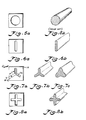
- Each of Figs. 6-12 illustrates a spinneret capillary having a differently shaped cross-sectional area including at least one lobe-shaped portion.
- Each of Figs. 6-12 illustrate a multilobal capillary cross-section and a multilobal cross-section fiber filament.
- a comparison of Figs. 7b and 7c illustrates how an identically shaped spinneret capillary cross-sectional area can be used to produce a slightly differently shaped fiber filament by regulating the viscosity of the molten precursor being extruded or the cooling rate of the extruded filament.
- fibers or filaments having an average lobe thickness of no more than 15 ⁇ m can be produced.
- multilobe fibers or filaments can be prepared wherein the circumferential distance between any two adjacent lobes of the fiber is the same.
- the method for producing a high elastic modulus, high tensile strength carbon fiber comprises rendering the fiber filament infusible.
- the filament is rendered infusible by heating the filament in an environment including oxygen, e.g. air atmosphere at about 300°C for approximately two hours.
- oxygen e.g. air atmosphere at about 300°C for approximately two hours.
- the solidified filament is rendered infusible by oxidizing the filament.
- the method for producing a high elastic modulus, high tensile strength carbon fiber comprises heating the fiber filament in an inert environment at a temperature sufficient to substantially increase the tensile strength and modulus of elasticity of the fiber filament.
- This heating step in an inert, i.e., non-oxidizing, environment takes place after the fiber filament has been rendered infusible.
- the fiber filament was carbonized by raising the filament to a temperature of about 1500°C in an oxygen-free atmosphere for approximately five minutes.
- this environment is provided by a nitrogen atmosphere or other inert, i.e., non-oxidizing, environment, such as argon gas.
- one of the spinnerets 14 shown in Figs. 5-12 was attached to cartridge 12 and filled with a plurality of chips 16 of a pitch precursor.
- the cartridge was then heated by means of a heating collar 18 surrounding the cartridge.
- Back pressure was applied to the pitch precursor by an hydraulic piston 20, which forced a ram down into the cartridge.
- this constant pressure hydraulic piston extruded the melt 24 through the capillary 26 of spinneret 14 into a quench cabinet 28.
- the filaments 30 were taken up on a variable speed winder bobbin 32.
- Cartridge 12 was prepared in the following manner. First, anti-seize lubricant was applied to all screws (not shown), the thermocouple (not shown) and the pressure probe connections (not shown). With the cartridge up-side-down, a metal screen (not shown) and an aluminum ring (not shown) were placed in the bottom of the cartridge. One of the spinnerets shown in Figs. 5-12 was chosen and screwed into the bottom of the cartridge. With the cartridge right-side-up, the thermocouple and pressure probe were screwed into the side of the cartridge. The cartridge was filled with the solid pitch precursor chips to within 2.54 cm (one inch) from the top. A graphite packing ring 34 and ram 22 were placed into the top of the cartridge. The cap was screwed into the top of the cartridge. Then, the complete cartridge was placed into the heating collar, and the thermocouple and pressure probe leads were connected.
- the desired collar temperature set point was set on a temperature controller 36. Collar temperature, melt temperature, melt pressure and hydraulic pressure were monitored. The collar controls set point was readjusted as necessary to maintain the desired spin temperature in the melt as read on a melt temperature read out 38. After the desired spin temperature in the melt was attained, the desired melt pressure was set. Once the desired melt temperature and melt pressure were obtained, a sample was weighed over a known time period, and the mass flow rate was calculated. Using the calculated mass flow rate, the winder speed necessary to achieve the desired draw-down rate (the ratio of spinneret capillary cross-section to a desired cross-section) was determined and recorded. The winder speed controller 40 was set to the position corresponding to the calculator winder speed. Filaments were collected on the winder until an adequate sample had been obtained. The quench air temperature in the quench cabinet was monitored.
- the oxidation protocol followed in operation of the embodiment of the invention illustrated in Figs. 3 and 4 proceeded as follows.
- a sample of filament was first heated in an oxidation chamber 42 in an air environment at a temperature of 225°C for a 30 minute period. Then, the temperature was ramped over a 30 minute period from 225°C to 265°C. Finally, the filament sample was maintained at a temperature of 265°C for a period of approximately 180 minutes.
- the carbonization protocol proceeded as follows.
- the oxidized sample of filament was transported through a furnace 44 at a rate of approximately one half foot per minute (15.2 cm/min) in an oxygen-free environment of nitrogen gas.
- the sample filament was maintain at a temperature of approximately 900°C.
- the sample was maintained at a temperature of approximately 1500°C.
- the sample filament was maintained at the nominal carbonization temperature.
- a petroleum pitch based precursor 24 was prepared by solvent extraction techniques as described in US-A-4,208,267.
- the precursor was placed in cartridge 12 and melted at approximately 335°C.
- hydraulic piston 20 was engaged to apply a substantially constant pressure and extrude precursor 24 at a constant flow rate through capillary 26 of spinneret 14.
- the precursor solidified as it emerged from capillary 26 into an ambient air atmosphere and was wound up on bobbin 32. Solidification of the precursor was observed to have occurred by the time that filament 30 reached a distance of approximately one inch (2.5 cm) downstream from the capillary opening.
- the fiber filaments were oxidized and carbonized as described above, which were typical commercial conditions for circular carbon fibers.
- the multilobal carbon fiber of the present invention has several advantages over the conventional carbon fiber of circular cross-section.
- One advantage of the multilobal carbon fiber of the present invention is the larger surface area to volume present in the multilobal fiber. This characteristic should improve the wetability of the fiber, and this should yield improved performance in applications where wetability is important.
- the multilobal fiber can be spun with a larger cross-sectional area than a circular fiber.
- the effective diameter of a non-circular fiber is defined as the diameter of a hypothetical circular fiber with an equivalent cross-sectional area.
- the multilobal fiber of the present invention is stronger than a circular fiber of comparable effective diameter.
- the moduli of elasticity were calculated as the slope of the stress versus strain curve generated during the tensile strength measurement.
- the photomicrographs shown in Figs. 13-15 and 18 were obtained using a scanning electron microscope (SEM).
- Fig. 13 shows a typical SEM photomicrograph magnification of the conventional circular carbon fibers produced using the apparatus illustrated in Fig. 3.
- the SEM photo clearly shows that the fiber microstructure is radial in nature.
- the crystallites shown in the photo as light colored streaks
- This radial structure is typical of carbon fibers spun from mesophase pitch and having a circular transverse cross-sectional area.
- the conventional circular carbon fiber transverse cross-section shown in plan view in Fig. 13 has a measured diameter of 14.8 ⁇ m, a tensile strength of 244.2 ksi (1.68 G Pa) and a modulus of elasticity of 35.13 msi (0.24 TPa).
- This fiber was produced with the winder running at a speed of 1469 feet per minute (448 m/min).
- the capillary of the spinneret used to produce this fiber has a diameter of 0.25 millimeters (mm) and a depth of 1 mm.
- the melt temperature was 358°C and the melt pressure was 204 pounds per square inch (psi) (1407 kPa). This particular sample weighed 1.35 grams (g) and was collected over an eight minute time span.
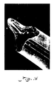
- Figs. 14 and 15 The SEM's of typical trilobal fibers are shown in Figs. 14 and 15. Note that the microstructure of these fibers differs from that of the circular fiber shown in Fig. 13. In trilobal fibers, the microstructure does not emanate from a center point, but instead emanates from three centerlines extending from the tip of each lobe. This line-origin microstructure of the trilobal carbon fiber of the present invention contrasts with the point-origin microstructure of a conventional circular carbon fiber in Fig. 13. It is believed that the improved strength of the multilobal fibers of the present invention is caused by this line-origin microstructure.
- the cause of the improved strength of the trilobal fibers also may be the shorter distance required for oxygen diffusion in a trilobal fiber versus a circular fiber of equivalent cross-sectional area during the oxidation step. Because the trilobal fiber has a greater surface-to-volume ratio, there is more surface available for oxygen to diffuse into the fiber during oxidation. Moreover, because of its trilobal shape, no portion of the trilobal fiber is as thick as the circular fiber of equivalent area. This keeps the oxygen from having to travel as far in the trilobal fiber as the oxygen must travel in the circular fiber to reach the core.
- Figs. 14 and 15 are typical of the trilobal and circular fibers and indicates fewer surface flaws in the trilobal fiber. This also would tend to give higher strength to the trilobal fibers.
- the larger surface-to-volume ratio of a trilobal fiber probably allows a trilobal fiber to more effectively release gas both during fiber formation at extrusion and during the oxidation and carbonization steps than is possible with a circular fiber.
- the trilobal fiber shown in Fig. 14 was produced using a spinneret having a cross-sectional area shaped as illustrated in Fig. 7a.
- This trilobal fiber was oxidized and carbonized under the same conditions as described above.
- the capillary of the spinneret used to produce this fiber had a width of 0.127 mm, a depth of 0.889 mm, a characteristic length of 0.305 mm and an area of 0.109 mm2.
- the take-up speed of the winder was 1129 feet per minute (344 m/min) during the spinning of this filament, which has a measured diameter of 16.3 ⁇ m and an effective diameter of 13 ⁇ m.
- the melt temperature was 353°C, and the melt pressure was 443 psi (3054 kPa).
- the tensile strength was determined to be 240.2 ksi (1.66 GPa) and the modulus of elasticity was determined to be 32.7 msi (0.22 TPa).
- the trilobal fiber shown in Fig. 15 was produced using a spinneret having a cross-sectional area shaped as illustrated in Fig. 7a. This trilobal fiber was oxidized and carbonized under the same conditions as described above.
- the spinneret used in producing the sample had a lobe width of 0.127 mm, a depth of approximately 0.381 mm, a characteristic length of 0.305 mm and an area of 0.109 mm2.
- the take-up speed of the winder was 1413 feet per minute (431 m/min) during the spinning of this sample, which had a measured diameter of 16.4 ⁇ m and a calculated effective diameter of 12.6 ⁇ m.
- the melt temperature was 355°C, and the melt pressure varied between 188 and 200 psi (1296 to 1380 kPa).
- This particular sample weighed 2.28 grams and was collected over a 15 minute time span.
- This particular fiber exhibited a tensile strength of 301 ksi (2.07 GPa) and a modulus of elasticity of 40.75 msi (0.281 TPa).
- the carbonizations at temperatures above 1500°C actually represent a first carbonization at 1500°C followed by a further carbonization at a higher temperature.
- the circular fibers were spun at spin temperatures of 353 to 354°C through a spinneret capillary 0.25 mm in diameter, 1.0 mm in depth and 0.0491 mm2 cross-sectional area.
- the extrusion rate and winderspeed were slightly altered from the parameters set in producing the fibers shown in Fig. 13, to produce circular fibers with the desired range of diameters.
- the trilobal fibers were spun at 353°C through the same spinneret capillary used to produce the fiber shown in Fig. 15 and described in Example 2.
- Fig. 16 is a plot of tensile strength versus carbonization temperature. These results show that the trilobal fibers of the present invention consistently have a higher ultimate tensile strength then the conventional circular fibers. While a linear least squares fit of the data shows that the strength of the circular fibers remains relatively constant with carbonization temperature, the trilobal fiber strength increases rapidly and reaches values as high as 395 ksi (2.72 GPa) at 1900°C. The modulus of elasticity of these trilobal fibers is also consistently higher than the circular fibers as shown in Fig. 17, and also reaches a maximum value of 108 msi (0.74 TPa) at 1900°C. Each data point in Figs. 16 and 17 represents an average of ten single filament tests.
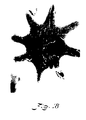
- Fig. 18 shows an SEM of an octalobal fiber made using a spinneret with an octalobal-shaped cross-section capillary as shown in Fig. 12.
- the octalobal fiber of the present invention shown in Fig. 18 has a measured diameter of 42.8 ⁇ m and an effective diameter of 31.3 ⁇ m.
- the tensile strength of this fiber was measured to be 176.2 ksi (1.21 GPa) and the modulus of elasticity was 28.9 msi (0.199 TPa). This fiber was produced with a winder running at a speed of 879 feet per minute (268 m/min).
- the capillary of the spinneret used to produce this fiber has a lobe length of 0.457 mm, a lobe width of 0.0889 mm, a depth of 0.305 mm, and an area of 0.287 mm2.
- the melt temperature was 355-357°C, and the melt pressure was 255 to 381 psi (1760-2630 kPa).
- the particular octalobal capillary used to produce the fiber photographed in Fig. 18 had a 485 percent larger cross-sectional area than the cross-sectional area of the circular fiber shown in Fig. 13. Accordingly, the smallest octalobal fibers which could be spun with the melt spinning apparatus of Fig. 3, had an effective diameter of 18.7 ⁇ m.
- the large size of the octalobal-shaped fiber made it difficult to oxidize and carbonize, as indicated by the gas void in the fiber shown in Fig. 18. Nevertheless, the octalobal fiber shown in Fig. 18 exhibits the characteristic line-origin microstructure, which emanates from the centerline of each lobe, and the strength of this fiber is still superior to the strength of a conventional circular carbon fiber with a diameter of 31.3 ⁇ m.
Landscapes
- Engineering & Computer Science (AREA)
- Textile Engineering (AREA)
- Chemical & Material Sciences (AREA)
- Chemical Kinetics & Catalysis (AREA)
- General Chemical & Material Sciences (AREA)
- Manufacturing & Machinery (AREA)
- Mechanical Engineering (AREA)
- Inorganic Fibers (AREA)
- Spinning Methods And Devices For Manufacturing Artificial Fibers (AREA)
Claims (15)
- Verfahren zur Herstellung einer Kohlenstoffaser mit hohem Elastizitätsmodul und hoher Zugfestigkeit, bestehend aus den Schritten, daß
eine geschmolzene Vorstufe bereitgestellt wird, die einen wesentlichen Anteil kohlenstoffhaltigen anisotropen Materials enthält,
die geschmolzene Vorstufe auf einer solchen Temperatur gehalten wird, daß ihre Viskosität in den Bereich zwischen 25 Pa.s (250 Poise) und 200 Pa.s (2000 Poise) fällt,
die geschmolzene Vorstufe durch eine Spinndüse extrudiert wird, die ein Kapillarrohr mit zumindest einem lappenförmigen Querschnittsbereich bildet,
die extrudierte Vorstufe bei ihrem Austritt aus der Spinndüse zu einem Faserfaden mit einem Querschnitt im wesentlichen gleich dem Querschnitt des Kapillarrohrs verfestigt wird,
der Faserfaden unschmelzbar gemacht wird und danach der Faserfaden in einer inerten Umgebung bei einer solchen Temperatur erwärmt wird, daß die Zugfestigkeit und der Elastizitätsmodul des Faserfadens wesentlich erhöht werden. - Verfahren nach Anspruch 1, bei dem der Schritt des Unschmelzbarmachens des Faserfadens ein Erwärmen des Faserfadens in einer sauerstoffhaltigen Umgebung einschließt.
- Verfahren nach Anspruch 1 oder Anspruch 2, bei dem der Schritt des Erwärmens des Fadens in einer inerten Umgebung in Stickstoffgas durchgeführt wird.
- Verfahren nach Anspruch 1, 2 oder 3, bei dem die Spinndüse ein Kapillarrohr bildet, das drei lappenförmige Querschnittsbereiche besitzt und der aus der Spinndüse austretende extrudierte Faserfaden zu einer Faser mit einem dreilappigen Querschnitt verfestigt wird.
- Verfahren nach Anspruch 4, bei dem die Spinndüse ein Kapillarrohr mit einer T-förmigen Querschnittsfläche bildet und die aus der Spinndüse austretende extrudierte Vorstufe zu einem Faserfaden mit einem T-förmigen Querschnitt verfestigt wird.
- Verfahren nach Anspruch 4, bei dem die Spinndüse ein Kapillarrohr mit einer Y-förmigen Querschnittsfläche bildet und die aus der Spinndüse austretende extrudierte Vorstufe zu einem Faserfaden mit einem im wesentlichen Y-förmigen Querschnitt verfestigt wird.
- Verfahren nach Anspruch 1, 2 oder 3, bei dem die Spinndüse ein Kapillarrohr mit vier lappenförmigen Querschnittsbereichen bildet und die aus der Spinndüse austretende extrudierte Vorstufe zu einem Faserfaden mit einem vierlappigen Querschnitt verfestigt wird.
- Verfahren nach Anspruch 1, 2 oder 3, bei dem die Spinndüse ein Kapillarrohr mit fünf lappenförmigen Querschnittsbereichen bildet und die aus der Spinndüse austretende extrudierte Vorstufe zu einem Faserfaden mit einem fünflappigen Querschnitt verfestigt wird.
- Verfahren nach Anspruch 1, 2 oder 3, bei dem die Spinndüse ein Kapillarrohr mit sechs lappenförmigen Querschnittsbereichen bildet und die aus der Spinndüse austretende extrudierte Vorstufe zu einem Faserfaden mit einem sechslappigen Querschnitt verfestigt wird.
- Verfahren nach Anspruch 1, 2 oder 3, bei dem die Spinndüse ein Kapillarrohr mit acht lappenförmigen Querschnittsbereichen bildet und die aus der Spinndüse austretende extrudierte Vorstufe zu einem Faserfaden mit einem achtlappigen Querschnitt verfestigt wird.
- Kohlenstoffaser mit zumindest einem Lappen, wobei der oder jeder Lappen im Querschnitt dem Faser eine von einer entlang der Länge des Lappens verlaufenden Linie nach außen hervortretende Mikrostruktur aufweist.
- Kohlenstoffaser nach Anspruch 11, bei der die durchschnittliche Lappendicke nicht mehr als etwa 15 µm beträgt.
- Kohlenstoffaser mit einem mehrlappigen Querschnitt, hoher Zugfestigkeit und hohem Elastizitätsmodul, wobei jeder Lappen im Querschnitt der Faser eine von einer entlang der Länge des Lappens verlaufenden Linie nach außen hervortretende Mikrostruktur aufweist.
- Kohlenstoffaser nach Anspruch 13, bei der der Umfangsabstand zwischen zwei beliebigen benachbarten Lappen der Faser der gleiche ist.
- Kohlenstoffaser nach Anspruch 13, bei der die Zugfestigkeit im Bereich von etwa 176,2 ksi (1,21 GPa) bis etwa 395 ksi (2,72 GPa) und der Elastizitätsmodul im Bereich von etwa 28,9 msi (0,199 TPa) in etwa 108 msi (0,74 TPa) liegt.
Applications Claiming Priority (2)
| Application Number | Priority Date | Filing Date | Title |
|---|---|---|---|
| US06/775,131 US5154908A (en) | 1985-09-12 | 1985-09-12 | Carbon fibers and method for producing same |
| US775131 | 1985-09-12 |
Publications (2)
| Publication Number | Publication Date |
|---|---|
| EP0219964A1 EP0219964A1 (de) | 1987-04-29 |
| EP0219964B1 true EP0219964B1 (de) | 1991-07-31 |
Family
ID=25103424
Family Applications (1)
| Application Number | Title | Priority Date | Filing Date |
|---|---|---|---|
| EP86306936A Expired EP0219964B1 (de) | 1985-09-12 | 1986-09-09 | Verfahren zur Herstellung von Kohlenstoffasern und diese Kohlenstoffasern |
Country Status (4)
| Country | Link |
|---|---|
| US (1) | US5154908A (de) |
| EP (1) | EP0219964B1 (de) |
| JP (1) | JPS62117821A (de) |
| DE (1) | DE3680632D1 (de) |
Families Citing this family (23)
| Publication number | Priority date | Publication date | Assignee | Title |
|---|---|---|---|---|
| US5149517A (en) * | 1986-01-21 | 1992-09-22 | Clemson University | High strength, melt spun carbon fibers and method for producing same |
| US5156831A (en) * | 1986-01-21 | 1992-10-20 | Clemson University | Method for producing high strength, melt spun carbon fibers |
| US4915926A (en) * | 1988-02-22 | 1990-04-10 | E. I. Dupont De Nemours And Company | Balanced ultra-high modulus and high tensile strength carbon fibers |
| JP2640528B2 (ja) * | 1989-02-22 | 1997-08-13 | 日本石油株式会社 | ピッチ系炭素繊維 |
| JP2892127B2 (ja) * | 1989-09-05 | 1999-05-17 | 東レ株式会社 | 非円形断面炭素繊維、その製造方法および炭素繊維複合材料 |
| JPH0397918A (ja) * | 1989-09-05 | 1991-04-23 | Toray Ind Inc | 異形断面炭素繊維の製造法 |
| KR0156870B1 (ko) * | 1989-09-05 | 1998-12-01 | 마에다 가쓰노스케 | 비원형단면 탄소섬유의 제조방법 및 이를 이용한 복합재료 |
| JPH0397917A (ja) * | 1989-09-05 | 1991-04-23 | Toray Ind Inc | 異形断面炭素繊維およびその製造方法 |
| US6583075B1 (en) | 1999-12-08 | 2003-06-24 | Fiber Innovation Technology, Inc. | Dissociable multicomponent fibers containing a polyacrylonitrile polymer component |
| US20080058848A1 (en) * | 2003-07-28 | 2008-03-06 | Don Griffin | Endcap for a Sampling Device |
| US7165963B2 (en) * | 2003-10-31 | 2007-01-23 | Invista North America S.A.R.L. | Spinneret for producing circular cross section yarn and process for making the same |
| US8293107B1 (en) * | 2005-10-19 | 2012-10-23 | The United States Of America As Represented By The Secretary Of The Air Force | Fibers with axial capillary slit that enhances adsorption, absorption and separation |
| JP4274256B2 (ja) * | 2006-08-25 | 2009-06-03 | トヨタ自動車株式会社 | 蓄電装置用電極及び蓄電装置 |
| JP2014517777A (ja) * | 2011-02-24 | 2014-07-24 | ホーワキ,リミテッド ライアビリティー カンパニー | 微細構造を有する部品を押出し加工するシステムおよび方法 |
| TWD172988S (zh) * | 2015-05-06 | 2016-01-11 | 陳 清靈 | 紡織纖維的單絲 |
| WO2017006234A1 (en) * | 2015-07-04 | 2017-01-12 | Reliance Industries Limited | Polyester fiber |
| US11692284B2 (en) | 2016-08-18 | 2023-07-04 | Aladdin Manufacturing Corporation | Trilobal filaments and spinnerets for producing the same |
| USD841838S1 (en) | 2016-11-04 | 2019-02-26 | Mohawk Industries, Inc. | Filament |
| US10981096B2 (en) | 2017-03-29 | 2021-04-20 | Knowlton Technologies, Llc | Process for making high efficiency synthetic filter media |
| US20230295842A1 (en) * | 2019-03-04 | 2023-09-21 | University Of Kentucky Research Foundation | Method of making polyacrylonitrile based carbon fibers and polyacrylonitrile based carbon fiber fabric |
| WO2021203027A1 (en) * | 2020-04-02 | 2021-10-07 | Aladdin Manufacturing Corporation | Ribbon like filaments and systems and methods for producing the same |
| JP7522387B2 (ja) * | 2020-06-16 | 2024-07-25 | 日本電気硝子株式会社 | 異形断面ガラス繊維用ノズル、及び、異形断面ガラス繊維の製造方法 |
| WO2026019455A1 (en) * | 2024-07-16 | 2026-01-22 | National Technology & Engineering Solutions Of Sandia, Llc | Non-circular carbon fiber for cost-specific compressive strength |
Family Cites Families (14)
| Publication number | Priority date | Publication date | Assignee | Title |
|---|---|---|---|---|
| US3303530A (en) * | 1965-01-13 | 1967-02-14 | Du Pont | Spinnerette |
| NL6516064A (de) * | 1965-12-10 | 1967-06-12 | ||
| US3419936A (en) * | 1967-01-31 | 1969-01-07 | Monsanto Co | Spinneret for melt spinning filaments |
| US3478389A (en) * | 1967-10-19 | 1969-11-18 | Monsanto Co | Spinneret |
| US4208267A (en) * | 1977-07-08 | 1980-06-17 | Exxon Research & Engineering Co. | Forming optically anisotropic pitches |
| US4301135A (en) * | 1979-12-26 | 1981-11-17 | Union Carbide Corporation | Process for spinning pitch fiber into a hot gaseous environment |
| JPS58209857A (ja) * | 1982-05-31 | 1983-12-06 | Matsushita Electronics Corp | メタルハライドランプ |
| US4511625A (en) * | 1982-09-30 | 1985-04-16 | Union Carbide Corporation | Physical conversion of latent mesophase molecules to oriented molecules |
| JPS59168126A (ja) * | 1983-03-14 | 1984-09-21 | Toray Ind Inc | ピツチ系炭素繊維の製造方法 |
| JPS59163424A (ja) * | 1983-03-09 | 1984-09-14 | Kashima Sekiyu Kk | 石油系メソフエ−ズの紡糸法 |
| JPS59168115A (ja) * | 1983-03-15 | 1984-09-21 | Toray Ind Inc | ピツチの溶融紡糸方法 |
| JPH0781211B2 (ja) * | 1983-11-10 | 1995-08-30 | 株式会社ペトカ | 炭素繊維の製造方法 |
| JPS6147826A (ja) * | 1984-08-15 | 1986-03-08 | Teijin Ltd | ピツチ系炭素繊維の製造法 |
| JPS616314A (ja) * | 1984-06-20 | 1986-01-13 | Teijin Ltd | ピツチ系炭素繊維 |
-
1985
- 1985-09-12 US US06/775,131 patent/US5154908A/en not_active Expired - Fee Related
-
1986
- 1986-09-09 DE DE8686306936T patent/DE3680632D1/de not_active Expired - Lifetime
- 1986-09-09 EP EP86306936A patent/EP0219964B1/de not_active Expired
- 1986-09-12 JP JP61214205A patent/JPS62117821A/ja active Pending
Also Published As
| Publication number | Publication date |
|---|---|
| JPS62117821A (ja) | 1987-05-29 |
| EP0219964A1 (de) | 1987-04-29 |
| US5154908A (en) | 1992-10-13 |
| DE3680632D1 (de) | 1991-09-05 |
Similar Documents
| Publication | Publication Date | Title |
|---|---|---|
| EP0219964B1 (de) | Verfahren zur Herstellung von Kohlenstoffasern und diese Kohlenstoffasern | |
| US5149517A (en) | High strength, melt spun carbon fibers and method for producing same | |
| Edie et al. | Melt spinning pitch-based carbon fibers | |
| US4628001A (en) | Pitch-based carbon or graphite fiber and process for preparation thereof | |
| US4005183A (en) | High modulus, high strength carbon fibers produced from mesophase pitch | |
| Fitzer et al. | Carbon reinforcements and carbon/carbon composites | |
| Edie et al. | Melt-spun non-circular carbon fibers | |
| US3919376A (en) | Process for producing high mesophase content pitch fibers | |
| US5156831A (en) | Method for producing high strength, melt spun carbon fibers | |
| US3919387A (en) | Process for producing high mesophase content pitch fibers | |
| US5168004A (en) | Melt-spun acrylic fibers possessing a highly uniform internal structure which are particularly suited for thermal conversion to quality carbon fibers | |
| Edie et al. | Ribbon-shape carbon fibers for thermal management | |
| CA1333954C (en) | Formation of melt-spun acrylic fibers which are particularly suited for thermal conversion to high strength carbon fibers | |
| CA1317422C (en) | Formation of melt-spun acrylic fibers possessing a highly uniform internal structure which are particularly suited for thermal conversion to quality carbon fibers | |
| US4115527A (en) | Production of carbon fibers having high anisotropy | |
| EP0031707A2 (de) | Verfahren zur Herstellung von Kohlenstoffasern | |
| Mochida et al. | Control of transversal texture in circular mesophase pitch-based carbon fibre using non-circular spinning nozzles | |
| US5399330A (en) | Carbon thread and process for producing it | |
| US5037590A (en) | Method for the preparation of carbon fibers | |
| JPH0370012B2 (de) | ||
| US4356158A (en) | Process for producing carbon fibers | |
| CA1055664A (en) | Rapid thermosetting of carbonaceous fibers produced from mesophase pitch | |
| Edie | The effect of processing on the structure and properties | |
| US4859382A (en) | Process for preparing carbon fibers elliptical in section | |
| JP2849156B2 (ja) | 中空炭素繊維の製造方法 |
Legal Events
| Date | Code | Title | Description |
|---|---|---|---|
| PUAI | Public reference made under article 153(3) epc to a published international application that has entered the european phase |
Free format text: ORIGINAL CODE: 0009012 |
|
| AK | Designated contracting states |
Kind code of ref document: A1 Designated state(s): BE DE FR GB IT NL |
|
| 17P | Request for examination filed |
Effective date: 19871012 |
|
| 17Q | First examination report despatched |
Effective date: 19891221 |
|
| GRAA | (expected) grant |
Free format text: ORIGINAL CODE: 0009210 |
|
| ITF | It: translation for a ep patent filed | ||
| AK | Designated contracting states |
Kind code of ref document: B1 Designated state(s): BE DE FR GB IT NL |
|
| PG25 | Lapsed in a contracting state [announced via postgrant information from national office to epo] |
Ref country code: NL Effective date: 19910731 |
|
| ET | Fr: translation filed | ||
| REF | Corresponds to: |
Ref document number: 3680632 Country of ref document: DE Date of ref document: 19910905 |
|
| NLV1 | Nl: lapsed or annulled due to failure to fulfill the requirements of art. 29p and 29m of the patents act | ||
| PLBE | No opposition filed within time limit |
Free format text: ORIGINAL CODE: 0009261 |
|
| STAA | Information on the status of an ep patent application or granted ep patent |
Free format text: STATUS: NO OPPOSITION FILED WITHIN TIME LIMIT |
|
| 26N | No opposition filed | ||
| PGFP | Annual fee paid to national office [announced via postgrant information from national office to epo] |
Ref country code: GB Payment date: 19930913 Year of fee payment: 8 |
|
| PGFP | Annual fee paid to national office [announced via postgrant information from national office to epo] |
Ref country code: FR Payment date: 19930921 Year of fee payment: 8 |
|
| PGFP | Annual fee paid to national office [announced via postgrant information from national office to epo] |
Ref country code: BE Payment date: 19930928 Year of fee payment: 8 |
|
| PGFP | Annual fee paid to national office [announced via postgrant information from national office to epo] |
Ref country code: DE Payment date: 19931001 Year of fee payment: 8 |
|
| PG25 | Lapsed in a contracting state [announced via postgrant information from national office to epo] |
Ref country code: GB Effective date: 19940909 |
|
| PG25 | Lapsed in a contracting state [announced via postgrant information from national office to epo] |
Ref country code: BE Effective date: 19940930 |
|
| BERE | Be: lapsed |
Owner name: CLEMSON UNIVERSITY Effective date: 19940930 |
|
| GBPC | Gb: european patent ceased through non-payment of renewal fee |
Effective date: 19940909 |
|
| PG25 | Lapsed in a contracting state [announced via postgrant information from national office to epo] |
Ref country code: FR Effective date: 19950531 |
|
| PG25 | Lapsed in a contracting state [announced via postgrant information from national office to epo] |
Ref country code: DE Effective date: 19950601 |
|
| REG | Reference to a national code |
Ref country code: FR Ref legal event code: ST |
|
| PG25 | Lapsed in a contracting state [announced via postgrant information from national office to epo] |
Ref country code: IT Free format text: LAPSE BECAUSE OF NON-PAYMENT OF DUE FEES Effective date: 20050909 |