EP0222443A2 - Multiprozessrechner und abhängiges Betriebssystem - Google Patents
Multiprozessrechner und abhängiges Betriebssystem Download PDFInfo
- Publication number
- EP0222443A2 EP0222443A2 EP86201901A EP86201901A EP0222443A2 EP 0222443 A2 EP0222443 A2 EP 0222443A2 EP 86201901 A EP86201901 A EP 86201901A EP 86201901 A EP86201901 A EP 86201901A EP 0222443 A2 EP0222443 A2 EP 0222443A2
- Authority
- EP
- European Patent Office
- Prior art keywords
- interrupt
- routine
- context
- user
- driver
- Prior art date
- Legal status (The legal status is an assumption and is not a legal conclusion. Google has not performed a legal analysis and makes no representation as to the accuracy of the status listed.)
- Ceased
Links
Images


Classifications
-
- G—PHYSICS
- G06—COMPUTING OR CALCULATING; COUNTING
- G06F—ELECTRIC DIGITAL DATA PROCESSING
- G06F9/00—Arrangements for program control, e.g. control units
- G06F9/06—Arrangements for program control, e.g. control units using stored programs, i.e. using an internal store of processing equipment to receive or retain programs
- G06F9/46—Multiprogramming arrangements
- G06F9/48—Program initiating; Program switching, e.g. by interrupt
- G06F9/4806—Task transfer initiation or dispatching
- G06F9/4812—Task transfer initiation or dispatching by interrupt, e.g. masked
Definitions
- the invention relates to a multiprocess computer and a method for operating same. Such processes are divided into operating system routines which are controlled by respective application programs or modules thereof and user processes that are executed with respect to executing a user- required function.
- a typical non-limiting example, for which the invention was conceived and reduced to practice, is the VAX-11-750 Computer by Digital Equipment Corporation, Maynard, Massachusetts, USA.
- Many aspects of the operating system or so-called executive thereof are described in the book "VAX/VMS Internals and Data Structures", by L.J. Kenah and S.F. Bate, published by Digital Press, Bedford Massachusetts USA 1984.
- the scheduling of process execution is done by the scheduler according to either of two principles:
- operating system routines usually are provided with an interrupt feature.
- the highest interrupt priority level is the "power-down-signaliza- tion”.
- Lower interrupt priority levels relate to I/O- handling.
- Operating system routines are executed in system context. User processes usually are not provided with an interrupt feature, so that they are only executed if the system software does not need activation.
- the present invention mitigates the disadvantages of the earlier solution in ⁇ that for a specific peripheral, and for predetermined interrupt signals associated thereto an instantly activatable high priority level is assigned.
- a dialog with this peripheral may be executed at real-time, wherein also the optimum context to the process in question is present and accessible.
- One specific example is a magnetic resonance imaging apparatus for medical diagnostic use for which a delay of an attention or completion interrupt would necessitate certain measurements on patients to be repeated which could cause distress, loss of apparatus time and/or increased cost.
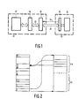
- Figure 1 is a block diagram of a computer for use with the invention, for example, a VAX-11-750-Computer, provided with a VAX/VMS operating system of release 3.7.
- the central computer 20 is provided with a UNIBUS-adaptor 24, a UNIBUS- interface 26, and further elements such as processor and main store, generally shown as block 22.
- the UNIBUS-proper is indicated by label 25; the bus can support a plurality of interfaces 26, each interface for an associated peripheral device.
- Peripheral device 29 is also provided with an interface 30 to element 26 and further elements 32, such as the peripheral function proper (I/O-function, control card).
- the computer-to-peripheral device connection 28 has a physical multiplicity and may have an appreciable length in that the peripheral device is situated at a remote location.
- Connection 28 is accompanied by an attention line 34 on which the peripheral device may signal that it needs attention from the central computer, e.g., in that it must transmit or receive data, or that a specific control must be executed.
- Interface element 26 receives the attention requesting signal and translates this to an attention interrupt to be forwarded to the processor. In certain cases a so-called "completion interrupt" may be generated by interface element 26.
- One applicable example is that a certain amount of data is being sent to peripheral device 28, while at the end of this transmission operation the processor must execute a certain function. Thereto interface element 26 monitors the transport and at the end thereof independently generates this completion interrupt.
- FIG. 2 explains the respective priority levels in an exemplary computer, to wit, the VAX-11-750- machines etcetera.
- the left hand block enumerates several of the maximum of thirty-two interrupt priority levels.
- Level 31 is the highest level and is activated by the an electric power failure resulting in the execution of the power-down routine: upon activation several key informations are saved into non-volatile storage elements for allowing a controlled restart when power returns.
- Levels 20-23 are assigned to respective I/O-operations on the UNIBUS, which must be served fast, for example to avoid an "idle" state in a high volume printer or to accommodate reception of a block of data from a magnetic disk.
- Such operations may be, for example start/stop operations controlled by a direct- memory-access (DMA) activity.
- DMA direct- memory-access
- Levels 8-11 are assigned to the necessary pre-processing and post-processing for such I/O-operations.
- An example of pre-processing is the calculation of a physical memory address where the next I/O-operation is to begin.
- An example of post-processing is the ascertaining of acknowledge signals to verify whether an output operation had been executed correctly. If such verification is deemed unnecessary, the post-processing in question may be omitted.
- Each level is assigned to a particular peripheral or group of peripherals so that the input/output processes also in this respect have interrupting power among themselves. In certain cases in principle levels 8-11 and 20-23 may be combined to a single group of levels, or even to a single level. If two processes have the same interrupt priority level they cannot interrupt each other in either of the two directions.
- Levels 4-7 are assigned to the processes of the context switching to accommodate the context, e.g. hardware register contents to a newly activated process.
- the associated interrupt may be activated, e.g. by the clock if non-real-time processes are awoken and put to sleep, respectively, at the beginning and end of their assigned time slices.
- the real-time process in question initates the associated interrupt. The specific meaning of real-time in prior VAX-usage is explained elsewhere.
- Level 2 is assigned to specific user program- originated program modules; the normal level for user programs is level zero, which of course means that their facility to interrupt is only notional because there is no lower level where a potential victim program could have operated.
- the user software generally operates without interrupt facilities (while, of course, itself is interruptable by all levels of 1 and up). Besides the levels of interrupt priority as shown, others may be implemented or left unoccupied by intent.
- FIG. 1 The right hand side of Figure 1 explains the two normal levels of user program execution.
- the software modules in region A are called "real- time". In fact, they are interruptable by all higher interrupt levels; however, they have a specific feature, in that execution proceeds (when uninterrupted) as long as processing is usefull.
- processes in region B are only assigned time slices of predetermined length and upon attaining the end of the time slice, execution is terminated anyway.
- a specific feature of the VAX-operating system is that one user program in either category A or B may be quasi-real-time, in that it is assigned a higher interrupt level.
- the invention alleviates the problems, by modifying the software, in particular the driver program of the peripheral device in question. The specifics of this modification will be described hereinafter.
- the allocating of a raised priority level to the user process in question has been indicated by an arrow from the user process (drawn by hatching) to interrupt priority levels 20..23 in the left hand block.
- two or more different user processes may have assigned a high priority level.
- the resulting level need not be in the same region, while in principle also a user process of region B could have such assignation. If required, all these latter user processes could have the context switching.
- the invention may be based on exclusively software measures. In any way, this results in a physical limitation to the functioning of the computer, in that a certain peripheral may now be really real-time driven, and therefore could function more adequately. In certain critical situations, proper functioning without the practising of the present invention, i.e. according to earlier practice would be impossible, or would anyway required intricate programming in machine language (macro).
- the interrupt service routine may be written in a so-called high-level language. One of the few requirements would be that all code and data that could be used in executing this interrupt service routine were present in main store, because the improved software would care for all virtual addressing. However, if the driver were to start the interrupt service routine with part of these code/data in background store, (e.g. magnetic disc) then the system would go into a "crashed" state.
- FIG. 3 for reasons of recapitulation gives a block diagram of a driver execution sequence.
- the driver is the control program in the central computer for the peripheral device in question.
- Express reference is had the series "VAX/VMS Software", in particular Volume 9 of the 3.0 release, produced by DEC.
- the changes to release 3.7 have been included in the present disclosure if and when relevant.
- Page 1.3 of the chapter "Guide to writing a device driver” lists substantially all important call categories to driver routines:
- the present invention deals substantially with the fifth of the categories.
- a listing is shown of the actual context in which the processor executes, and of the actual stack, i.e. main store area which can be used for temporary dumping a program counter position of an incomplete process for allowing later return.
- the listing starts when in block 40 the user process issues an I/O-request (DOL QIO).
- Blocks 42-46 are the first steps of the I/O-servicing where the preprocessing takes place, still in the user process context.
- Blocks 48-52 complete the initial operations before starting the actual I/O-operation.
- Blocks 54-62 are the realm of the driver wherein the invention would produce enhancement. Notably, blocks 54, 56, 58 refer to the beginning of an interrupt operation.
- Blocks 60, 62 refer to the terminating of an I/O-operation.
- the combination of interrupt context and fork process context is together system-determined context, not user process context. Therefore, as seen from the left hand column, never will the user process context appear in the way prior art would handle this interrupt. The latter only reappears in blocks 66, 68, but this is only after the initial interrupt operations had been executed. Finally in blocks 68 an asynchronous trap routine is executed at the low user level.
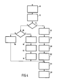
- Figure 4 is a modified flow chart according to the invention relating to an attention interrupt handling. In fact, it is an extension to page 11, 2 of the cited "Guide to writing a device driver” chapter, and would represent a modification of blocks 54-62 in Figure 4. In fact blocks 80-84, 96-106 are replicates from this page 11.2.
- the flow chart is entered in block 80 via an interrupt. However, if the incoming interrupt has a priority level which is not higher than the level of the operation presently being executed, this interrupt is ignored and put on a waiting list for later processing. Furthermore, if the interrupt had emanated from an operating system routine, it is directly processed in the system context without entering this flow chart.
- block 84 it is detected whether the interrupt was solicited by the system. If the interrupt is non- solicited and therefore autonomous, it is detected in block 86 whether it is a "device attention interrupt". This may be detected by specific data accompanying the interrupt proper, e.g. one or more signalling bits.
- the "attention" interrupt would in principle require immediate service. If it is not an attention interrupt, in block 88 the interrupt is rejected as spurious. However, if it is an attention interrupt, first in block 90 the context is switched to the one of the user process in question. Next, in block 92 the process attention interrupt procedure is executed. Finally in block 94 the context is switched back to the original one, and the system reverts to block 104 according to the known driver structure.
- Figure 5 is a modified flow chart relating to a completion interrupt handling. Blocks corresponding to Figure 4 have corresponding numbers. Thus, blocks 80-84, 96-106 need no further consideration. Figure 5 does not have the provisions for an attention interrupt as discussed with respect to Figure 4. Thus, blocks 88, 108, 110 represent the state of the art with respect to handling such attention interrupt.
- block 84 it is detected whether the interrupt was solicited, that is, whether the processor, as a result of some earlier outcome, had concluded that at some future instant this particular interrupt was to follow. In the positive case, after reactivation of the suspended driver (block 96) it is determined, whether the I/O-operation, being executed up till then, was provided with the real-time feature discussed earlier.
- blocks 114, 116, 118 are executed. These correspond closely to blocks 90, 92, 94, respectively, of Figure 4, apart from block 92 wherein the process completion interrupt procedure is executed. Finally, all branches of the flow chart reunite into block 104.
- Figure 6 shows the software blocks as components of the driver program. Specific reference is had to the chapter "Template for an I/O-driver" of the cited manual, pages 6.5-6.8. Each block is provided with an identifier stating the essential functions of the block. The right hand column refers to the line numbers of the driver print-out annexed hereto.
- UCB means "Unit Control block”.
- block 124 the location of the code or information for the operating system is indicated. Specifically, the context switch is. executed under control of block 138. It should be noted that this picture is not a flow chart.
Landscapes
- Engineering & Computer Science (AREA)
- Software Systems (AREA)
- Theoretical Computer Science (AREA)
- Physics & Mathematics (AREA)
- General Engineering & Computer Science (AREA)
- General Physics & Mathematics (AREA)
- Debugging And Monitoring (AREA)
- Executing Machine-Instructions (AREA)
- Input From Keyboards Or The Like (AREA)
Applications Claiming Priority (2)
| Application Number | Priority Date | Filing Date | Title |
|---|---|---|---|
| US79486385A | 1985-11-04 | 1985-11-04 | |
| US794863 | 1985-11-04 |
Publications (2)
| Publication Number | Publication Date |
|---|---|
| EP0222443A2 true EP0222443A2 (de) | 1987-05-20 |
| EP0222443A3 EP0222443A3 (de) | 1988-09-21 |
Family
ID=25163910
Family Applications (1)
| Application Number | Title | Priority Date | Filing Date |
|---|---|---|---|
| EP86201901A Ceased EP0222443A3 (de) | 1985-11-04 | 1986-10-31 | Multiprozessrechner und abhängiges Betriebssystem |
Country Status (3)
| Country | Link |
|---|---|
| EP (1) | EP0222443A3 (de) |
| JP (1) | JPS62235645A (de) |
| CA (1) | CA1273114A (de) |
Cited By (1)
| Publication number | Priority date | Publication date | Assignee | Title |
|---|---|---|---|---|
| CN101751000B (zh) * | 2008-12-04 | 2013-01-09 | 鸿富锦精密工业(深圳)有限公司 | 数控加工设备中断控制系统及其控制方法 |
Family Cites Families (3)
| Publication number | Priority date | Publication date | Assignee | Title |
|---|---|---|---|---|
| US3221309A (en) * | 1961-08-10 | 1965-11-30 | Scam Instr Corp | Priority interrupt monitoring system |
| GB1240978A (en) * | 1970-03-25 | 1971-07-28 | Ibm | Data processing systems |
| US3984820A (en) * | 1975-06-30 | 1976-10-05 | Honeywell Information Systems, Inc. | Apparatus for changing the interrupt level of a process executing in a data processing system |
-
1986
- 1986-10-29 CA CA000521745A patent/CA1273114A/en not_active Expired
- 1986-10-31 EP EP86201901A patent/EP0222443A3/de not_active Ceased
- 1986-11-04 JP JP26082986A patent/JPS62235645A/ja active Pending
Cited By (1)
| Publication number | Priority date | Publication date | Assignee | Title |
|---|---|---|---|---|
| CN101751000B (zh) * | 2008-12-04 | 2013-01-09 | 鸿富锦精密工业(深圳)有限公司 | 数控加工设备中断控制系统及其控制方法 |
Also Published As
| Publication number | Publication date |
|---|---|
| JPS62235645A (ja) | 1987-10-15 |
| CA1273114A (en) | 1990-08-21 |
| EP0222443A3 (de) | 1988-09-21 |
Similar Documents
| Publication | Publication Date | Title |
|---|---|---|
| US4972312A (en) | Multiprocess computer and method for operating same having context switching in response to a peripheral interrupt | |
| EP0106669B1 (de) | Organisationsprogramm für Betriebssysteme | |
| KR101514088B1 (ko) | 가상화된 환경에서의 최적화된 인터럽트 전달 | |
| JP3335172B2 (ja) | データ処理システム及びそれに使用するための入出力プロセッサ | |
| EP0783734B1 (de) | Vorrichtung und verfahren für kooperative unterbrechungen in einer preemptiven prozessablauffolgeplanungsumgebung | |
| US3984820A (en) | Apparatus for changing the interrupt level of a process executing in a data processing system | |
| US4020471A (en) | Interrupt scan and processing system for a data processing system | |
| KR100977662B1 (ko) | 2-레벨 인터럽트 서비스 루틴을 제공하기 위한 방법 및 프로세서 | |
| US8166349B2 (en) | Communicating with USB devices after a computer system crash | |
| JPH02171934A (ja) | 仮想計算機システム | |
| US5410709A (en) | Mechanism for rerouting and dispatching interrupts in a hybrid system environment | |
| JPS6258341A (ja) | 入出力割込処理方式 | |
| US6154832A (en) | Processor employing multiple register sets to eliminate interrupts | |
| US5887169A (en) | Method and apparatus for providing dynamic entry points into a software layer | |
| US5790887A (en) | Method and apparatus for processing programmed input/output (PIO) operations in a computer system | |
| EP0290942B1 (de) | Gastmaschinenablaufsteuerungssystem für virtuelles Maschinensystem | |
| EP0222443A2 (de) | Multiprozessrechner und abhängiges Betriebssystem | |
| US6263421B1 (en) | Virtual memory system that is portable between different CPU types | |
| US8151028B2 (en) | Information processing apparatus and control method thereof | |
| JPH0668725B2 (ja) | データ処理システムにおける割込条件に応答する装置及び非同期割込条件に応答する方法 | |
| JPH0290331A (ja) | 仮想計算機システムのためのプロセツサ間通信命令処理装置 | |
| JP2575761B2 (ja) | ジョブ管理方法 | |
| JPH0677236B2 (ja) | I/o割込みをシミュレートする装置及び方法 | |
| Lauesen | Program control of operating systems | |
| JPH09282297A (ja) | デュアルポートメモリを用いたcpu間通信シス テム |
Legal Events
| Date | Code | Title | Description |
|---|---|---|---|
| PUAI | Public reference made under article 153(3) epc to a published international application that has entered the european phase |
Free format text: ORIGINAL CODE: 0009012 |
|
| AK | Designated contracting states |
Kind code of ref document: A2 Designated state(s): DE FR GB |
|
| PUAL | Search report despatched |
Free format text: ORIGINAL CODE: 0009013 |
|
| AK | Designated contracting states |
Kind code of ref document: A3 Designated state(s): DE FR GB |
|
| 17P | Request for examination filed |
Effective date: 19890316 |
|
| 17Q | First examination report despatched |
Effective date: 19910410 |
|
| STAA | Information on the status of an ep patent application or granted ep patent |
Free format text: STATUS: THE APPLICATION HAS BEEN REFUSED |
|
| 18R | Application refused |
Effective date: 19911005 |
|
| RIN1 | Information on inventor provided before grant (corrected) |
Inventor name: DEN BOEF, JOHANNES HENDRIK |