EP0225440A1 - Moteur d'induction à grande vitesse - Google Patents
Moteur d'induction à grande vitesse Download PDFInfo
- Publication number
- EP0225440A1 EP0225440A1 EP86112809A EP86112809A EP0225440A1 EP 0225440 A1 EP0225440 A1 EP 0225440A1 EP 86112809 A EP86112809 A EP 86112809A EP 86112809 A EP86112809 A EP 86112809A EP 0225440 A1 EP0225440 A1 EP 0225440A1
- Authority
- EP
- European Patent Office
- Prior art keywords
- rotor
- rotor core
- core
- slots
- induction motor
- Prior art date
- Legal status (The legal status is an assumption and is not a legal conclusion. Google has not performed a legal analysis and makes no representation as to the accuracy of the status listed.)
- Withdrawn
Links
- 230000006698 induction Effects 0.000 title claims abstract description 36
- 239000004020 conductor Substances 0.000 claims abstract description 53
- 238000004804 winding Methods 0.000 claims abstract description 22
- 229910052802 copper Inorganic materials 0.000 claims abstract description 17
- 239000010949 copper Substances 0.000 claims abstract description 17
- RYGMFSIKBFXOCR-UHFFFAOYSA-N Copper Chemical compound [Cu] RYGMFSIKBFXOCR-UHFFFAOYSA-N 0.000 claims abstract description 16
- 238000001816 cooling Methods 0.000 claims abstract description 13
- 125000006850 spacer group Chemical group 0.000 claims abstract description 11
- RTAQQCXQSZGOHL-UHFFFAOYSA-N Titanium Chemical compound [Ti] RTAQQCXQSZGOHL-UHFFFAOYSA-N 0.000 claims abstract description 7
- 239000010936 titanium Substances 0.000 claims abstract description 7
- 229910052719 titanium Inorganic materials 0.000 claims abstract description 7
- 239000010935 stainless steel Substances 0.000 claims abstract description 4
- 229910001220 stainless steel Inorganic materials 0.000 claims abstract description 4
- 238000009413 insulation Methods 0.000 claims description 6
- XEEYBQQBJWHFJM-UHFFFAOYSA-N Iron Chemical group [Fe] XEEYBQQBJWHFJM-UHFFFAOYSA-N 0.000 claims description 4
- 229910052751 metal Inorganic materials 0.000 claims description 3
- 239000002184 metal Substances 0.000 claims description 3
- 150000001875 compounds Chemical class 0.000 claims description 2
- 230000000149 penetrating effect Effects 0.000 claims 5
- 230000000452 restraining effect Effects 0.000 claims 3
- 239000000498 cooling water Substances 0.000 claims 1
- 229920000136 polysorbate Polymers 0.000 claims 1
- XLYOFNOQVPJJNP-UHFFFAOYSA-N water Substances O XLYOFNOQVPJJNP-UHFFFAOYSA-N 0.000 abstract description 8
- 235000019628 coolness Nutrition 0.000 abstract 1
- 239000003921 oil Substances 0.000 description 7
- 229910000831 Steel Inorganic materials 0.000 description 6
- 239000010959 steel Substances 0.000 description 6
- 229910000851 Alloy steel Inorganic materials 0.000 description 4
- 241000555745 Sciuridae Species 0.000 description 2
- 238000003475 lamination Methods 0.000 description 2
- 230000004048 modification Effects 0.000 description 2
- 238000012986 modification Methods 0.000 description 2
- 230000002093 peripheral effect Effects 0.000 description 2
- 230000036316 preload Effects 0.000 description 2
- 239000007787 solid Substances 0.000 description 2
- KQZLRWGGWXJPOS-NLFPWZOASA-N 1-[(1R)-1-(2,4-dichlorophenyl)ethyl]-6-[(4S,5R)-4-[(2S)-2-(hydroxymethyl)pyrrolidin-1-yl]-5-methylcyclohexen-1-yl]pyrazolo[3,4-b]pyrazine-3-carbonitrile Chemical compound ClC1=C(C=CC(=C1)Cl)[C@@H](C)N1N=C(C=2C1=NC(=CN=2)C1=CC[C@@H]([C@@H](C1)C)N1[C@@H](CCC1)CO)C#N KQZLRWGGWXJPOS-NLFPWZOASA-N 0.000 description 1
- 229910000976 Electrical steel Inorganic materials 0.000 description 1
- 229940125877 compound 31 Drugs 0.000 description 1
- 238000010276 construction Methods 0.000 description 1
- 230000007812 deficiency Effects 0.000 description 1
- 230000009977 dual effect Effects 0.000 description 1
- 230000000694 effects Effects 0.000 description 1
- 230000004907 flux Effects 0.000 description 1
- 230000001939 inductive effect Effects 0.000 description 1
- 239000012774 insulation material Substances 0.000 description 1
- 229910052742 iron Inorganic materials 0.000 description 1
- 239000000463 material Substances 0.000 description 1
- 230000007246 mechanism Effects 0.000 description 1
- 230000000717 retained effect Effects 0.000 description 1
- 229920002379 silicone rubber Polymers 0.000 description 1
- -1 silicone rubber Chemical compound 0.000 description 1
- 239000004945 silicone rubber Substances 0.000 description 1
Images

Classifications
-
- H—ELECTRICITY
- H02—GENERATION; CONVERSION OR DISTRIBUTION OF ELECTRIC POWER
- H02K—DYNAMO-ELECTRIC MACHINES
- H02K3/00—Details of windings
- H02K3/04—Windings characterised by the conductor shape, form or construction, e.g. with bar conductors
- H02K3/24—Windings characterised by the conductor shape, form or construction, e.g. with bar conductors with channels or ducts for cooling medium between the conductors
-
- H—ELECTRICITY
- H02—GENERATION; CONVERSION OR DISTRIBUTION OF ELECTRIC POWER
- H02K—DYNAMO-ELECTRIC MACHINES
- H02K17/00—Asynchronous induction motors; Asynchronous induction generators
- H02K17/02—Asynchronous induction motors
- H02K17/16—Asynchronous induction motors having rotors with internally short-circuited windings, e.g. cage rotors
-
- H—ELECTRICITY
- H02—GENERATION; CONVERSION OR DISTRIBUTION OF ELECTRIC POWER
- H02K—DYNAMO-ELECTRIC MACHINES
- H02K5/00—Casings; Enclosures; Supports
- H02K5/04—Casings or enclosures characterised by the shape, form or construction thereof
- H02K5/16—Means for supporting bearings, e.g. insulating supports or means for fitting bearings in the bearing-shields
- H02K5/173—Means for supporting bearings, e.g. insulating supports or means for fitting bearings in the bearing-shields using bearings with rolling contact, e.g. ball bearings
- H02K5/1732—Means for supporting bearings, e.g. insulating supports or means for fitting bearings in the bearing-shields using bearings with rolling contact, e.g. ball bearings radially supporting the rotary shaft at both ends of the rotor
-
- H—ELECTRICITY
- H02—GENERATION; CONVERSION OR DISTRIBUTION OF ELECTRIC POWER
- H02K—DYNAMO-ELECTRIC MACHINES
- H02K9/00—Arrangements for cooling or ventilating
- H02K9/19—Arrangements for cooling or ventilating for machines with closed casing and closed-circuit cooling using a liquid cooling medium, e.g. oil
- H02K9/197—Arrangements for cooling or ventilating for machines with closed casing and closed-circuit cooling using a liquid cooling medium, e.g. oil in which the rotor or stator space is fluid-tight, e.g. to provide for different cooling media for rotor and stator
Definitions
- This invention relates to induction motors, and is particularly directed to an improved high speed induction motor.
- the basic components of the invention induction motor which cooperate to achieve the improved results comprise a random wound, water cooled three phase stator assembly, a solid alloy steel rotor with copper conductors and titanium end caps, and an oil jet lubricated bearing system.
- the stator is the random wound type and is insulated preferably with a so-called Class H insulation system.
- the windings provide the rotating field necessary for induction motor operation.
- the laminated core assembly is enclosed in a water jacket to dissipate the heat generated due to electrical losses. Further cooling of the stator windings can be provided by water cooling coils wound around and bonded, with a thermally conductive compound, to the winding end turns.
- the rotor is the main feature of the present invention.
- the motor rotor and shaft is composed of a single piece of alloy steel. Copper conductors or bars fit into semiclosed slots which are machined into the rotor periphery. Radial restraint of the bars in the core section is provided by the projections of the rotor teeth at the semiclosed end of the slots. Copper end rings are brazed to the bars to complete the secondary electrical circuit.
- the end rings are held a distance from the steel rotor core by means of non-magnetic metal spacers and are restrained by means of uniquely formed titanium end caps which fit tightly on the rotor shaft and are held in place with cap screws.
- Circumferential grooves are cut into the rotor to a depth preferably greater than the depth of the rotor conductors prior to the assembly of the rotor, and shallow grooves or threads are also cut into the surface of the rotor, for purposes herinafter discussed.
- the bearing system is composed of two precision angular contact ball bearing at each end of the rotor shaft. These bearings are separated by spacers and oil jet rings so that the preload provided by wave springs is maintained. Oil, under pressure is forced through two jets to each of the bearings. Return oil is conducted through passages in the housing to an external sump where it is cooled and filtered.
- Another object of the present invention is the provision of a novel induction motor system which operates efficiently at high speed and delivering greater horsepower.
- a particular object of the invention is to provide an improved high speed induction motor which operates at high speeds and horsepower, without the danger of rotor instability or rotor failure due to centrifugal forces, or due to high amplitude deflections and high forces.
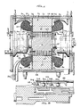
- the squirrel cage high speed induction motor of the invention comprises a random wound, water cooled three phase stator assembly 10, a solid alloy steel rotor assembly 12 coaxially mounted within the stator, and an oil jet lubricated bearing system for the rotor, indicated at 14, as described in detail below.
- the stator 10 and rotor 12 are mounted and assembled in a suitable frame 15.
- the stator 10 comprises an insulated three phase winding, indicated at 16 to generate the required rotating magnetic field, wound on a core 18 forming a stator stack.
- the stator stack is composed of silicon steel laminations 20 held together with six building bars 22 and stainless steel (non-magnetic) end plates 24.
- the stainless steel end plates 24 are provided with projections 26 which support the laminations at the ends of the stator teeth 27.
- the non-magnetic property of the bars 22 and end plates 24 serves to reduce the losses due to the rotating field which is in close proximity to the end plates.
- layers of insulation 28 are provided around the windings 16, and the stator windings are cooled by means of water circulated through metallic tubing 30 which is wound circumferentially around the outer diameter of the end turn portions of the windings 16.
- the layers of insulation 28 between the windings 16 and the cooling coils 30 assure that the electrical integrity of the winding is preserved.
- the voids around the cooling coils 30 are encapsulated with a suitable compound 31, such as silicone rubber, to prevent movement of the coils and facilitate heat transfer from the windings to the cooling coils.
- stator can be powered by a variable frequency, variable voltage inverter (not shown).
- water cooling passages 26 are provided in the outer jacket of the frame 15. Water cooling of the motor frame and of the stator winding removes the heat generated by the electrical losses and maintains the insulation 28 and winding insulation at a temperature less than 180°C. e.g. for a so-called Class H insulation material.
- the motor rotor 12 comprises a core section 37 and an integral output shaft 38, the rotor core and shaft being composed of a single piece of alloy steel.
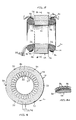
- a plurality of elongated copper conductor bars 40 fit into semiclosed elongated slots 42 which are provided in the core 37, the slots being equally spaced radially around the rotor periphery.
- the copper conductors 40 are configured so that they provide a tight fit in the rotor slots and almost completely fill the slots.
- the slots 42 are wedge shaped, converging radially toward the axis of the rotor, and have an outer narrow neck portion 44 adjacent the outer periphery of the rotor core, and the conductor bars 40 which fit into the slots are similarly wedge shaped and have an upper shoulder portion 46 abutting an adjacent shoulder portion 48 of the slot 42, and a narrow neck portion 50 which is accommodated within the neck portion 44 of the slot 42. It is seen that the top of the neck portion 50 of the conductor bars 40 coincides with the outer periphery of the rotor,and thus the rotor peripheral surface is smooth and the windage loss due to rotor rotation is thereby reduced.
- the radial portion of the rotor core between two adjacent conductor bars 40 forms a rotor tooth indicated at 54 having outer projections 56.
- outward radial restraint of the conductor bars 40 in the core section 37 of the rotor is provided by the projections 56 of the rotor teeth 54 at the semiclosed ends or neck portions 44 of the slots 42.
- the cross sectional configuration of the copper conductors 40 as wedges, and having radially downwardly convergent sides 58, allows the adjacent steel rotor teeth 54 to have parallel sides 60.
- This shape of the rotor teeth 54 provides more steel in the tooth portion of the rotor magnetic path, thereby reducing the magnetizing force required to maintain a given level of magnetic field.
- the wider tooth root also reduces the rotational stresses in the teeth.
- conductor bars 62 of rectangular cross section can be employed instead of the wedge shaped conductor bars 40.
- the radial slots 64 accommodating the conductor bars 62 also have parallel sides and hence the resulting rotor teeth 66 between adjacent conductor bars 62 have radially convergent sides 67 and thus the resulting rotor teeth 66 have less steel in the tooth root portion 68 ⁇ than in the root portion 55 of the rotor teeth 54.
- this embodiment is less preferred than the embodiment of Fig. 6, containing the wedge shaped conductor bars 40.
- conducting, e.g. copper, end rings 68 are provided at opposite ends of the rotor core 37.
- the copper end rings are each provided with a plurality of spaced slots 70 around its outer periphery, which extend completely through the end ring from one side 72 to the opposite side 74 of such ring.
- the slots 70 receive outwardly extending reduced size end portions 76 of the conductor bars 40 in closely fitting relation, and are brazed in place in the copper end rings to assure a good electrical contact and relatively high mechanical strength.
- the end rings 68 are maintained a distance from the ends of core section 37 of the steel rotor 12 by means of a nonmagnetic spacer 78, to reduce the electrical reactance of the end ring.
- the ring shaped spacers 78 extend radially from a shoulder 80 on the rotor shaft 38, outwardly to the base 82 of the elongated conductor bars 40.
- the copper end ring 68 must be restrained. This is accomplished by providing around each of rings 68 an end cap 84, preferably composed of titanium, which fits tightly on the rotor shaft 38 and is held in place with a plurality of spaced cap screws 86.
- the end caps 84 are provided with an outboard peripheral rim portion 88.
- the end cap 84 serves a dual function in that it also provides a means of balancing the rotor 12.
- the cross-sectional shape of the end cap 84 is such that the outer rim 88 is balanced, i.e.
- the radial force due to the copper end ring is partially balanced by the radial force due to the balance ring or outboard portion of the rim 88.
- the inner diameter of the end cap 84 is made slightly smaller than the corresponding portion of the rotor shaft 28.
- a shrink fit is obtained during the assembly of the end cap 84 on the rotor shaft 38, which reduces the tendency of the end cap to become loose on the shaft due to the rotational forces. This factor adds to the high speed stability of the rotor. It is seen that the end cap 84 completely encloses the copper end ring 68 except on the rotor core side.
- the end caps 84 are securely retained on the rotor by means of the cap screws 86 which pass through the end cap, end ring 68 and spacer 78, and are threaded at 90 into the rotor body core 37.
- Clearance holes 92 are provided through the end cap 84, end ring 68 and spacer 78, and partially into the rotor body 37, to allow the cap screws to deform radially over a controlled length as the rotor operates at speed.
- the material of the end caps must be non-magnetic, such as titanium to reduce the effect of flux fringing from the air gap and to reduce the reactance of the end rings 68.
- Circumferential grooves 94 are cut into the rotor core 37, along substantially the entire length of the rotor core, such grooves being cut into the rotor to a depth preferably below, i.e. radially inward of, the rotor conductor bars 40, prior to the assembly of the rotor. Such circumferential grooves serve to break up the currents in the iron teeth 54 of the rotor core 37, thereby reducing the losses in the iron core.
- Fine or shallow circumferential grooves 96 are also cut into the surface of the rotor core 37 between the circumferential grooves 94, along the length of the rotor. Such fine grooves or threading have a function similar to that of the circumferential grooves 94, for the higher frequency currents which only penetrate the surface of the steel core 37 to a shallow depth.
- the shaft 38 of the rotor is mounted for rotation on oppositely positioned bearing systems, indicated at 14.
- bearing systems are composed of two precision angular contact ball bearings 100. These bearings are separated by spacers 102 and oiling rings 104, so that the preload provided by wave springs 106 in the bearing assembly at the output shaft 38 is maintained. Oil under pressure is forced through two jets 108 to each of the inner race surfaces of the bearings. Return oil is conducted through passages (not shown) in the housing to an external sump (not shown) where it is cooled and filtered.
- This induction motor allows operation at speeds up to 18,000 RPM and delivers up to 300 horsepower.
- the motor operates to provide such brake horsepower output at the 18,000 RPM speed without excessive energy losses or excessive vibration.
- the invention provides a unique and improved squirrel cage type induction motor operating efficiently at high speed and horsepower not heretofore attainable.
- the design of the induction motor of the invention, particularly the rotor construction, provides high stability and resistance to failure due to centrifugal forces.
Landscapes
- Engineering & Computer Science (AREA)
- Power Engineering (AREA)
- Induction Machinery (AREA)
- Iron Core Of Rotating Electric Machines (AREA)
- Motor Or Generator Cooling System (AREA)
- Connection Of Motors, Electrical Generators, Mechanical Devices, And The Like (AREA)
- Rolling Contact Bearings (AREA)
Applications Claiming Priority (2)
| Application Number | Priority Date | Filing Date | Title |
|---|---|---|---|
| US06/808,195 US4644210A (en) | 1985-12-12 | 1985-12-12 | High speed induction motor with squirrel cage rotor |
| US808195 | 1985-12-12 |
Publications (1)
| Publication Number | Publication Date |
|---|---|
| EP0225440A1 true EP0225440A1 (fr) | 1987-06-16 |
Family
ID=25198128
Family Applications (1)
| Application Number | Title | Priority Date | Filing Date |
|---|---|---|---|
| EP86112809A Withdrawn EP0225440A1 (fr) | 1985-12-12 | 1986-09-17 | Moteur d'induction à grande vitesse |
Country Status (5)
| Country | Link |
|---|---|
| US (1) | US4644210A (fr) |
| EP (1) | EP0225440A1 (fr) |
| JP (1) | JPS62141945A (fr) |
| CA (1) | CA1265180A (fr) |
| DK (1) | DK601086A (fr) |
Cited By (8)
| Publication number | Priority date | Publication date | Assignee | Title |
|---|---|---|---|---|
| FR2627912A1 (fr) * | 1988-01-25 | 1989-09-01 | Westinghouse Electric Corp | Appareil et procede pour isolation de tubes de passage dans une bobine de stator |
| EP0343313A1 (fr) * | 1988-05-27 | 1989-11-29 | Gec Alsthom Acec Energie S.A. | Moteur électrique de puissance élevée et à vitesse de rotation élevée |
| US6177750B1 (en) | 1998-07-14 | 2001-01-23 | Reliance Electric Technologies, Llc | Rotating assembly construction for high speed induction motor |
| EP2779384A3 (fr) * | 2013-03-15 | 2016-11-09 | Ingersoll-Rand Company | Machine électrique à induction à haute vitesse |
| CN107104551A (zh) * | 2016-02-23 | 2017-08-29 | 福特全球技术公司 | 用于电气化车辆的热管理组件 |
| FR3086121A1 (fr) | 2018-09-19 | 2020-03-20 | Ge Energy Power Conversion Technology Limited | Rotor pour machine electrique asynchrone a arbre non traversant |
| FR3086130A1 (fr) | 2018-09-19 | 2020-03-20 | Ge Energy Power Conversion Technology Limited | Rotor pour machine electrique asynchrone a arbre non traversant et machine electrique associee |
| WO2025100732A1 (fr) * | 2023-11-06 | 2025-05-15 | 삼성전자 주식회사 | Rotor et moteur le comprenant |
Families Citing this family (47)
| Publication number | Priority date | Publication date | Assignee | Title |
|---|---|---|---|---|
| US4751417A (en) * | 1986-10-06 | 1988-06-14 | Sundstrand Corporation | Method of increasing operating efficiency of electric machines |
| WO1988002569A1 (fr) * | 1986-10-06 | 1988-04-07 | Sundstrand Corporation | Machine electrique et procede permettant d'accroitre le rendement de machines electriques |
| JPH07118880B2 (ja) * | 1986-10-15 | 1995-12-18 | フアナツク株式会社 | 高速回転用モ−タの軸受構造 |
| IT1208879B (it) * | 1987-04-30 | 1989-07-10 | Isoflux Servomotors Spa | Macchina elettrica a riluttanza |
| US4810918A (en) * | 1987-10-07 | 1989-03-07 | Flint & Walling, Inc. | Rotor shaft with corrosion resistant ferrule for pumps motor |
| US4874972A (en) * | 1987-12-30 | 1989-10-17 | Sundstrand Corporation | Magnetic isolation and cooling system in dynamoelectric machines |
| DE3834668A1 (de) * | 1988-10-12 | 1990-04-19 | Klein Schanzlin & Becker Ag | Druckfest gekapselter spaltrohrmotor |
| US5091666A (en) * | 1990-06-15 | 1992-02-25 | General Electric Company | Stator cooling system for electrical machinery |
| DE4209118C2 (de) * | 1991-12-23 | 1993-12-09 | Loher Ag | Asynchronmotor |
| US5363002A (en) * | 1993-07-28 | 1994-11-08 | Sundstrand Corporation | Dynamoelectric machine having fluid cooling of back iron and end turns |
| US5682074A (en) * | 1994-03-02 | 1997-10-28 | Northrop Grumman Corporation | Electric vehicle motor |
| JP3443248B2 (ja) * | 1996-07-30 | 2003-09-02 | 株式会社荏原製作所 | 水冷キャンドモータ |
| US5859482A (en) * | 1997-02-14 | 1999-01-12 | General Electric Company | Liquid cooled electric motor frame |
| SE517323C2 (sv) * | 1998-06-30 | 2002-05-28 | Emotron Ab | Kylningsanordning för en elektrisk maskin |
| US6859019B2 (en) | 2001-08-30 | 2005-02-22 | Honeywell International, Inc. | System and method for coupling rectifiers of an exciter to the rotor of a main generator |
| US6727634B2 (en) | 2001-08-30 | 2004-04-27 | Honeywell International, Inc. | System and method for end turn retention on a high speed generator rotor |
| US6791230B2 (en) | 2001-09-07 | 2004-09-14 | Honeywell International, Inc. | System and method for retaining wedges in a rotor |
| US6753637B2 (en) | 2001-09-07 | 2004-06-22 | Honeywell International, Inc. | Exciter rotor assembly |
| KR100421386B1 (ko) * | 2001-09-22 | 2004-03-09 | 엘지전자 주식회사 | 초고속용 유도 전동기의 회전자 |
| US6734585B2 (en) | 2001-11-16 | 2004-05-11 | Honeywell International, Inc. | Rotor end caps and a method of cooling a high speed generator |
| US6914354B2 (en) * | 2002-01-16 | 2005-07-05 | Ballard Power Systems Corporation | Assembly and method for direct cooling of motor end-winding |
| US6803688B2 (en) * | 2002-07-31 | 2004-10-12 | General Electric Company | Isolation of generator bearing housing from generator enclosure and methods therefor |
| CH695973A5 (de) * | 2002-08-16 | 2006-10-31 | Alstom Technology Ltd | Rotor für eine elektrische Maschine. |
| US20040061409A1 (en) * | 2002-09-30 | 2004-04-01 | Grant Barron D. | Method for making electrical stator and stator made by same |
| US6930427B2 (en) * | 2002-09-30 | 2005-08-16 | Reliance Electric Technologies, Llc | Electric apparatus having a stator with insulated end laminations within the central opening of end plates |
| US7057326B2 (en) * | 2003-05-29 | 2006-06-06 | General Electric Company | Rotor body containment shell with reduced windage losses |
| US20050017597A1 (en) * | 2003-07-23 | 2005-01-27 | Mays Harold H. | End ring support structure for electric motor |
| US20050093391A1 (en) * | 2003-11-03 | 2005-05-05 | Mcmullen Patrick T. | Sleeveless permanent magnet rotor construction |
| NL1026424C2 (nl) * | 2004-06-15 | 2005-12-19 | Siemens Ind Turbomachinery B V | Rotor voor elektromotor, compressoreenheid voorzien van rotor, werkwijze voor het vervaardigen van een rotor voor een elektromotor. |
| DE102005030798A1 (de) * | 2005-06-29 | 2007-01-04 | Siemens Ag | Läufer einer Asynchronmaschine |
| US7358637B2 (en) * | 2005-11-04 | 2008-04-15 | Canopy Technologies, Llc | Method of compressing lamination stacks for permanent magnet rotor |
| US7545060B2 (en) * | 2006-03-14 | 2009-06-09 | Gm Global Technology Operations, Inc. | Method and apparatus for heat removal from electric motor winding end-turns |
| US7675209B2 (en) * | 2007-02-01 | 2010-03-09 | Honeywell International Inc. | Electric motor cooling jacket |
| US7800259B2 (en) * | 2007-05-10 | 2010-09-21 | Gm Global Technology Operations, Inc. | Stator assembly for use in a fluid-cooled motor and method of making the same |
| US8143738B2 (en) * | 2008-08-06 | 2012-03-27 | Infinite Wind Energy LLC | Hyper-surface wind generator |
| US8084902B2 (en) * | 2009-05-06 | 2011-12-27 | Hamilton Sundstrand Corporation | End plates for high speed generator applications |
| US8008827B1 (en) * | 2010-02-18 | 2011-08-30 | Tesla Motors, Inc. | Triple layer winding pattern and methods of manufacturing same |
| US8274190B2 (en) | 2010-05-28 | 2012-09-25 | General Electric Company | Electric machine rotor bar and method of making same |
| AT509890B1 (de) * | 2010-06-14 | 2011-12-15 | Atb Motorenwerke Gmbh | Kurzschlussrotor |
| US20120326534A1 (en) * | 2010-12-28 | 2012-12-27 | Alexei Stadnik | Electrical actuators with grooved table top or housing |
| US8484828B2 (en) | 2011-07-19 | 2013-07-16 | GM Global Technology Operations LLC | Method for fabricating a rotor for an induction motor |
| US20140197702A1 (en) * | 2013-01-17 | 2014-07-17 | Remy Technologies, Llc | Electric motor rotor thermal interface with axial heat sinks |
| US10938280B2 (en) | 2013-11-01 | 2021-03-02 | Tesla, Inc. | Flux shield for electric motor |
| EP3726709B8 (fr) * | 2017-12-12 | 2024-06-05 | Toshiba Mitsubishi-Electric Industrial Systems Corporation | Machine électrique tournante à induction à cage d'écureuil, rotor plein et procédé de conception de machine électrique tournante à induction à cage d'écureuil |
| JP7405559B2 (ja) * | 2019-10-25 | 2023-12-26 | ファナック株式会社 | 冷却管を備えた電動機のステータ |
| US20220010734A1 (en) * | 2020-07-08 | 2022-01-13 | Ge Energy Power Conversion Technology Limited | Mechanical drive system and associated motor compressor |
| KR20230081421A (ko) * | 2021-11-30 | 2023-06-07 | 현대자동차주식회사 | 원주 방향 슬릿을 갖는 농형 회전자를 포함하는 유도모터 |
Citations (5)
| Publication number | Priority date | Publication date | Assignee | Title |
|---|---|---|---|---|
| FR1269226A (fr) * | 1960-06-29 | 1961-08-11 | Nouvelle Cie Generale Electr | Rotor perfectionné pour moteur à cage d'écureuil |
| US3260872A (en) * | 1964-04-13 | 1966-07-12 | Bendix Corp | Oil cooled generator design |
| US3681628A (en) * | 1970-09-14 | 1972-08-01 | Christoslaw Krastchew | Cooling arrangement for a dynamoelectric machine |
| CH566664A5 (fr) * | 1972-10-03 | 1975-09-15 | Acomel Sa | |
| DE2756685A1 (de) * | 1976-12-31 | 1978-07-06 | Asea Ab | Laeufer fuer asynchronmaschinen |
Family Cites Families (12)
| Publication number | Priority date | Publication date | Assignee | Title |
|---|---|---|---|---|
| US2286008A (en) * | 1940-08-02 | 1942-06-09 | Gen Electric | Magnetic core for electrical devices and method of making the same |
| US2372590A (en) * | 1942-10-05 | 1945-03-27 | Bryant Grinder Corp | High speed induction motor rotor |
| US2411002A (en) * | 1942-12-31 | 1946-11-12 | Rudenberg Reinhold | Damper system for synchronous generators |
| US2844745A (en) * | 1953-07-13 | 1958-07-22 | Gen Electric | Fluid-cooled dynamoelectric machine |
| US2781465A (en) * | 1955-03-15 | 1957-02-12 | Westinghouse Electric Corp | Rotor for electric motor |
| CH354838A (de) * | 1956-07-17 | 1961-06-15 | Asea Ab | Induktionsmotor mit einem mit dem Rotor des Motors rotierenden, axial verschiebbaren Magnetanker, z.B. zur Betätigung einer Bremse |
| US3075103A (en) * | 1959-09-30 | 1963-01-22 | Gen Electric | Fluid cooled chill ring for canned motors |
| US3060335A (en) * | 1961-02-07 | 1962-10-23 | Garrett Corp | Fluid cooled dynamoelectric machine |
| DE1291822B (de) * | 1965-10-11 | 1969-04-03 | Lloyd Dynamowerke Gmbh | Rotierende gleichstromerregte elektrische Maschine |
| US3502924A (en) * | 1968-06-27 | 1970-03-24 | Caterpillar Tractor Co | High speed rotor for dynamoelectric machine having laminations welded to stepped shaft and method of making the same |
| US3662200A (en) * | 1970-07-06 | 1972-05-09 | Gen Motors Corp | Squirrel cage rotor with interference fit sleeve between shaft and core |
| JPS6023584B2 (ja) * | 1977-12-14 | 1985-06-08 | 株式会社日立製作所 | 永久磁石式同期電動機 |
-
1985
- 1985-12-12 US US06/808,195 patent/US4644210A/en not_active Expired - Fee Related
-
1986
- 1986-08-27 CA CA000516945A patent/CA1265180A/fr not_active Expired - Fee Related
- 1986-09-17 EP EP86112809A patent/EP0225440A1/fr not_active Withdrawn
- 1986-12-11 JP JP61293572A patent/JPS62141945A/ja active Pending
- 1986-12-12 DK DK601086A patent/DK601086A/da not_active Application Discontinuation
Patent Citations (5)
| Publication number | Priority date | Publication date | Assignee | Title |
|---|---|---|---|---|
| FR1269226A (fr) * | 1960-06-29 | 1961-08-11 | Nouvelle Cie Generale Electr | Rotor perfectionné pour moteur à cage d'écureuil |
| US3260872A (en) * | 1964-04-13 | 1966-07-12 | Bendix Corp | Oil cooled generator design |
| US3681628A (en) * | 1970-09-14 | 1972-08-01 | Christoslaw Krastchew | Cooling arrangement for a dynamoelectric machine |
| CH566664A5 (fr) * | 1972-10-03 | 1975-09-15 | Acomel Sa | |
| DE2756685A1 (de) * | 1976-12-31 | 1978-07-06 | Asea Ab | Laeufer fuer asynchronmaschinen |
Non-Patent Citations (2)
| Title |
|---|
| PATENT ABSTRACTS OF JAPAN, vol. 7, no. 255 (E-210)[1400], 12th November 1983; & JP-A-58 141 641 (HITACHI SEISAKUSHO K.K.) 23-08-1983 * |
| PATENT ABSTRACTS OF JAPAN, vol. 8, no. 176 (E-260)[1613]; & JP-A-59 070 170 (TOSHIBA K.K.) 20-04-1984 * |
Cited By (10)
| Publication number | Priority date | Publication date | Assignee | Title |
|---|---|---|---|---|
| FR2627912A1 (fr) * | 1988-01-25 | 1989-09-01 | Westinghouse Electric Corp | Appareil et procede pour isolation de tubes de passage dans une bobine de stator |
| EP0343313A1 (fr) * | 1988-05-27 | 1989-11-29 | Gec Alsthom Acec Energie S.A. | Moteur électrique de puissance élevée et à vitesse de rotation élevée |
| US6177750B1 (en) | 1998-07-14 | 2001-01-23 | Reliance Electric Technologies, Llc | Rotating assembly construction for high speed induction motor |
| EP2779384A3 (fr) * | 2013-03-15 | 2016-11-09 | Ingersoll-Rand Company | Machine électrique à induction à haute vitesse |
| CN107104551A (zh) * | 2016-02-23 | 2017-08-29 | 福特全球技术公司 | 用于电气化车辆的热管理组件 |
| FR3086121A1 (fr) | 2018-09-19 | 2020-03-20 | Ge Energy Power Conversion Technology Limited | Rotor pour machine electrique asynchrone a arbre non traversant |
| FR3086130A1 (fr) | 2018-09-19 | 2020-03-20 | Ge Energy Power Conversion Technology Limited | Rotor pour machine electrique asynchrone a arbre non traversant et machine electrique associee |
| EP3627663A1 (fr) | 2018-09-19 | 2020-03-25 | GE Energy Power Conversion Technology Ltd. | Rotor pour machine électrique asynchrone à arbre non traversant et machine électrique associée |
| EP3627659A1 (fr) | 2018-09-19 | 2020-03-25 | GE Energy Power Conversion Technology Limited | Rotor pour machine electrique asynchrone a arbre non traversant |
| WO2025100732A1 (fr) * | 2023-11-06 | 2025-05-15 | 삼성전자 주식회사 | Rotor et moteur le comprenant |
Also Published As
| Publication number | Publication date |
|---|---|
| US4644210A (en) | 1987-02-17 |
| DK601086D0 (da) | 1986-12-12 |
| CA1265180A (fr) | 1990-01-30 |
| JPS62141945A (ja) | 1987-06-25 |
| DK601086A (da) | 1987-06-13 |
Similar Documents
| Publication | Publication Date | Title |
|---|---|---|
| EP0225440A1 (fr) | Moteur d'induction à grande vitesse | |
| US5220233A (en) | Dynamoelectric machines | |
| US4330726A (en) | Air-gap winding stator construction for dynamoelectric machine | |
| US4896062A (en) | Rotating rectifier assembly | |
| US5334899A (en) | Polyphase brushless DC and AC synchronous machines | |
| US6323573B1 (en) | High-efficiency inductor-alternator | |
| US5703421A (en) | Reluctance generator/motor cooling | |
| US11496025B2 (en) | Stator for an electric rotating machine | |
| US4556809A (en) | Combination synchronous and asynchronous electric motor | |
| EP0726638A2 (fr) | Machine tournante électromagnétique comprenant un palier électromagnétique | |
| US20080093850A1 (en) | Dual-structured aircraft engine starter/generator | |
| US4363986A (en) | Rotor of an electrical machine | |
| US5347188A (en) | Electric machine with enhanced liquid cooling | |
| US20240146134A1 (en) | Stator of an electric flux machine, and axial flux machine | |
| US3395299A (en) | Downset end winding rotor for dynamoelectric machine | |
| EP0489859B1 (fr) | Rotor a pertes par ventilation reduites | |
| US20140327330A1 (en) | Dynamoelectric machine having enhanced rotor ventilation | |
| US3894253A (en) | Very high current field winding for dynamoelectric machine rotor | |
| US3898491A (en) | Damper winding for turbine generator rotors | |
| US3866070A (en) | Turbo-generator of the radial slot type | |
| US5734217A (en) | Induction machine using ferromagnetic conducting material in rotor | |
| US4390806A (en) | Dynamoelectric machine rotors with mechanical separators | |
| US3562568A (en) | High performance dynamoelectric machine with permanent magnet stator | |
| US5736803A (en) | Synchronous machine rotor | |
| RU2246167C1 (ru) | Торцевая электрическая машина |
Legal Events
| Date | Code | Title | Description |
|---|---|---|---|
| PUAI | Public reference made under article 153(3) epc to a published international application that has entered the european phase |
Free format text: ORIGINAL CODE: 0009012 |
|
| AK | Designated contracting states |
Kind code of ref document: A1 Designated state(s): BE CH DE FR GB IT LI NL SE |
|
| 17P | Request for examination filed |
Effective date: 19871204 |
|
| 17Q | First examination report despatched |
Effective date: 19890920 |
|
| STAA | Information on the status of an ep patent application or granted ep patent |
Free format text: STATUS: THE APPLICATION IS DEEMED TO BE WITHDRAWN |
|
| 18D | Application deemed to be withdrawn |
Effective date: 19910323 |
|
| RIN1 | Information on inventor provided before grant (corrected) |
Inventor name: DONELAN, LYNN E. Inventor name: MEISNER, JOHN W. |