EP0225515A2 - Rohrschelle - Google Patents
Rohrschelle Download PDFInfo
- Publication number
- EP0225515A2 EP0225515A2 EP86116048A EP86116048A EP0225515A2 EP 0225515 A2 EP0225515 A2 EP 0225515A2 EP 86116048 A EP86116048 A EP 86116048A EP 86116048 A EP86116048 A EP 86116048A EP 0225515 A2 EP0225515 A2 EP 0225515A2
- Authority
- EP
- European Patent Office
- Prior art keywords
- pipe clamp
- clamping screw
- flange
- bracket
- screw
- Prior art date
- Legal status (The legal status is an assumption and is not a legal conclusion. Google has not performed a legal analysis and makes no representation as to the accuracy of the status listed.)
- Granted
Links
Images

Classifications
-
- F—MECHANICAL ENGINEERING; LIGHTING; HEATING; WEAPONS; BLASTING
- F16—ENGINEERING ELEMENTS AND UNITS; GENERAL MEASURES FOR PRODUCING AND MAINTAINING EFFECTIVE FUNCTIONING OF MACHINES OR INSTALLATIONS; THERMAL INSULATION IN GENERAL
- F16L—PIPES; JOINTS OR FITTINGS FOR PIPES; SUPPORTS FOR PIPES, CABLES OR PROTECTIVE TUBING; MEANS FOR THERMAL INSULATION IN GENERAL
- F16L3/00—Supports for pipes, cables or protective tubing, e.g. hangers, holders, clamps, cleats, clips, brackets
- F16L3/08—Supports for pipes, cables or protective tubing, e.g. hangers, holders, clamps, cleats, clips, brackets substantially surrounding the pipe, cable or protective tubing
- F16L3/10—Supports for pipes, cables or protective tubing, e.g. hangers, holders, clamps, cleats, clips, brackets substantially surrounding the pipe, cable or protective tubing divided, i.e. with two members engaging the pipe, cable or protective tubing
- F16L3/1008—Supports for pipes, cables or protective tubing, e.g. hangers, holders, clamps, cleats, clips, brackets substantially surrounding the pipe, cable or protective tubing divided, i.e. with two members engaging the pipe, cable or protective tubing with two members engaging the pipe, cable or tubing, both being made of thin band material completely surrounding the pipe
- F16L3/1016—Supports for pipes, cables or protective tubing, e.g. hangers, holders, clamps, cleats, clips, brackets substantially surrounding the pipe, cable or protective tubing divided, i.e. with two members engaging the pipe, cable or protective tubing with two members engaging the pipe, cable or tubing, both being made of thin band material completely surrounding the pipe the members being joined by means of two screws
-
- F—MECHANICAL ENGINEERING; LIGHTING; HEATING; WEAPONS; BLASTING
- F16—ENGINEERING ELEMENTS AND UNITS; GENERAL MEASURES FOR PRODUCING AND MAINTAINING EFFECTIVE FUNCTIONING OF MACHINES OR INSTALLATIONS; THERMAL INSULATION IN GENERAL
- F16L—PIPES; JOINTS OR FITTINGS FOR PIPES; SUPPORTS FOR PIPES, CABLES OR PROTECTIVE TUBING; MEANS FOR THERMAL INSULATION IN GENERAL
- F16L33/00—Arrangements for connecting hoses to rigid members; Rigid hose-connectors, i.e. single members engaging both hoses
- F16L33/02—Hose-clips
- F16L33/04—Hose-clips tightened by tangentially-arranged threaded pin and nut
Definitions
- the invention relates to a pipe clamp, consisting of an annular bracket with at least one opening, which can be closed by a clamping screw, the foot of which is mounted on one side of the opening with threaded engagement and the head of which on the other side of the opening in a with respect to the central longitudinal axis the pipe clamp can be hooked open radially on the inside in a flange attached to the bracket or in a part supported thereon.
- Such a clamp is z. B. described in DE-OS 33 08 459.
- the elongated hole in the flange is open radially on the inside with respect to the central longitudinal axis of the pipe clamp.
- the head of the clamping screw is passed through a sufficiently large hole in the bracket, which merges into the elongated hole. Since both flanges delimiting the opening of the one-piece clamp sit rigidly on the bracket, even with a thin pipe clamp, the mobility of the clamping screw required for hooking is only guaranteed if there is a lot of play between the pipe and the pipe clamp, i.e. its opening is very wide.
- the invention has for its object to provide a pipe clamp of the type mentioned, which is easy to handle and easy to close even with a very short clamping screw.
- the part in threaded engagement with the foot of the clamping screw is connected to the main part of the bracket via a joint
- the pivoting range of the clamping position and the relative inclined position of the flange and the clamping screw when they are inserted into the slot on his includes radially inner end and the pivot axis is arranged in the tensioned state of the pipe clamp between its central longitudinal axis and the central longitudinal axis of the clamping screw.
- the invention has the advantage that the clamping screw is pivoted regardless of the thickness of the pipe clamp and especially with only a slight clearance between the pipe and pipe clamp, ie narrow and even minimal opening gap when using a rubber insert, and therefore be very short for this reason and can be clamped with just a few turns.
- the advantage sought according to the invention decreases to the extent that the hinge axis approaches the central longitudinal axis of the clamping screw.
- the pivoting of the tension screw about a pivot axis lying essentially on its central longitudinal axis is to be regarded as a limit case.
- the invention provides that the head of the clamping screw can be passed axially through a hole in the flange with respect to its central longitudinal axis and through an elongated hole which is inserted between the head and the flange and is open at one end trained washer is held, which is preferably held positively in the tensioned state of the screw by this and / or the flange.
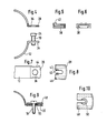
- Fig. 1 illustrates the different effects of the position of a defined hinge point on the movement conditions of the clamping screw when hooking into an elongated hole which is open radially on the inside with respect to the central longitudinal axis of the pipe clamp in a flange opposite the clamping screw at the opening of the pipe clamp.
- the center of the pipe clamp not shown, is located at a distance to the right of the clamping screw shown in each case. This is each articulated on the foot, but in all variants in different ways, and to pivot from the position shown in solid lines by the angle ⁇ to the dashed position when the head of the clamping screw from the radially inner side of the pipe clamp into there open slot is hooked into the opposite flange.
- FIG. 1 The left representation of Fig. 1 corresponds to a pipe clamp, as described in German patent application P 34 36 710.1.
- the right representation of FIG. 1 corresponds to a practical implementation z. 2, and the middle representation of FIG. 1 characterizes the conditions in a pipe clamp according to FIG. 3.
- a tensioning screw 10 the foot of which is screwed into a plate 14 which is articulated on the annular bracket 12 of the pipe clamp, a bracket-shaped part 16 or the like with thread engagement, when pivoting inward about the with 18 be Drawn joint axis on a circular arc, which leads relatively far in the circumferential direction of the ring-shaped pipe clamp bracket, ie in Fig. 1 and 2 relatively far up to the radially inner end of a flange 20 which extends radially inwardly from an enlarged hole 21, is provided radially closed slot 22 into which the head 24 of the clamping screw 10 can be hooked.
- FIG. 1 A counterexample, which corresponds to an embodiment according to German patent application P 34 36 710.1, is shown on the left in FIG. 1.
- the foot of the tensioning screw 10 is screwed into a tab or plate 28, which is articulated at 30 at the free end of a flange at the lower part of a pipe clamp, while the head of the tensioning screw is moved into an open from the inside by a movement from radially inside to radially outside Elongated hole of a flange should be hooked onto the upper part of the pipe clamp.
- the screw head lowers with increasing inclination, i. H. removed from the flange on which it is to be hooked.
- the pivot axis 18 of the joint should be on the side of the center point of the pipe clamp. It can also come close to the central longitudinal axis of the clamping screw. If, in addition, according to FIG. 3 and the middle representation of FIG. 1, the hinge axis intersects the screw axis, the screw length in the inclined position when hooking in must be somewhat larger than in the engagement position shown in dashed lines, but this excess, which is only necessary for the hooking-in process, can normally be found in practice can be tolerated taking into account the then relatively simple design of the pivot bearing.
- joint parts can also, such as. B. in Fig. 2, immediately hooked into each other.
- the joint could be arranged at a greater distance from the opening of the pipe clamp in the bracket.
- FIGS. 4 to 8 An alternative solution to the pipe clamps described so far is shown in FIGS. 4 to 8.
- both a flange 34 carrying the clamping screw 10 and the opposite flange 20 are rigidly connected to the bracket 12.
- the bracket 12 there is no narrow elongated hole in the flange 20, but rather a hole 36 that is so large in cross-section that the screw head 24 can be passed easily.
- the clamping screw 10 could then of course withdraw from the hole 36 without the aid of further measures.
- a washer according to FIGS. 5, 6 and 8, which is specially designed in the example is provided.
- this washer designated 38, has an elongated hole 40 which is open at one end, so that it can be pushed between the flange 20 and the screw head 24 after the screw head 24 has been passed through the hole 36. Then the screw extends shaft through the elongated hole 40, and the screw head 24, which is wider than the elongated hole 40, can no longer retract through the hole 36.
- the washer 38 is formed next to the elongated hole 40 at its open end with two opposite bumps 42, the spacing between which is smaller than the diameter of the screw head 24.
- the bumps 42 are next to the screw head 24 after tightening the clamping screw 10 and prevent the Washer 38 is lost or withdrawn.
- the flange 20 has opposite lateral recesses 44, and the washer 38 is angled laterally around the flange 20, behind it, as can be seen in FIG. 6. It thus leads in the radial direction on the flange 20.
- small lateral lugs 46 shown in FIG. 8 engage in the recesses 44, into which they have previously been snapped.
- the arrangement of the lugs 46 on that edge of the washer 38, at which the elongated hole 40 opens, and the length of the cutouts 44 with respect to the position of the hole 36 allow the washer 38 to be initially radially outward when the pipe clamp is installed withdraw that the screw head 24 can be passed through the hole 36. Thereafter, only the washer 38 needs to be pushed radially inward to lock the pipe clamp closure.
- the washer 48 shown there in longitudinal section and in plan view has a recess 50 in the central region. This is dimensioned so that it is smaller than the hole 36 in the flange 20.
- the recess 50 is partially pressed into the hole 36 by the tensioning screw 10, and the washer 48 is thereby positively held on the flange 20. If the recess 50 is also pronounced on the upper side of the washer 48, it should there be larger in outline than the screw head, so that the arrangement shown in FIG. 9 results in the assembled state.
Landscapes
- Engineering & Computer Science (AREA)
- General Engineering & Computer Science (AREA)
- Mechanical Engineering (AREA)
- Clamps And Clips (AREA)
- Supports For Pipes And Cables (AREA)
- Joints That Cut Off Fluids, And Hose Joints (AREA)
- Load-Engaging Elements For Cranes (AREA)
- Processing Of Terminals (AREA)
- Lasers (AREA)
- Investigating Or Analyzing Materials By The Use Of Magnetic Means (AREA)
Abstract
Description
- Die Erfindung betrifft eine Rohrschelle, bestehend aus einem ringförmigen Bügel mit wenigstens einer Öffnung, die durch eine Spannschraube schließbar ist, deren Fuß auf der einen Seite der Öffnung mit Gewindeeingriff gelagert und deren Kopf auf der anderen Seite der Öffnung in ein mit Bezug auf die Mittellängsachse der Rohrschelle radial innen offenes Langloch in einem am Bügel angebrachten Flansch oder einem an diesem abgestützten Teil einhakbar ist.
- Eine derartige Rohrschelle ist z. B. in der DE-OS 33 08 459 beschrieben. Das Langloch im Flansch ist mit Bezug auf die Mittellängsachse der Rohrschelle radial innen offen. Der Kopf der Spannschraube wird beim Einhaken durch ein ausreichend großes Loch im Bügel hindurchgeführt, welches in das Langloch übergeht. Da beide die Öffnung der einteiligen Schelle begrenzenden Flansche starr am Bügel sitzen, ist selbst bei einer dünnen Rohrschelle die zum Einhaken notwendige Beweglichkeit der Spannschraube nur dann gewährleistet, wenn viel Spiel zwischen dem Rohr und der Rohrschelle vorhanden, also deren Öffnung sehr weit ist. Dies bedingt eine lange Spannschraube und in Anbetracht der großen Zahl der bei einem Bauobjekt normalerweise zu montierenden Rohrschellen eine entsprechend lange Montagezeit zum Anziehen der Spannschrauben und hat außerdem den weiteren Nachteil, daß die im fertig montierten Zustand weit von der geschlossenen Rohrschelle abstehenden Schrauben gegebenenfalls störend oder gefährlich sein können.
- Bei einer anderen bekannten Rohrschelle gemäß DE-OS 33 46 423 ist der Fuß der Spannschraube in eine scheibenförmige Mutter eingeschraubt, die am Bügel der Rohrschelle derart schwenkbar gelagert ist, daß der Schraubenkopf von dem Bügel weg nach außen verschwenkt werden kann, um von dort aus in ein radial außen offenes Langloch in einem Flansch auf der anderen Seite der Öffnung der Rohrschelle eingehakt zu werden. Abgesehen von dem Mangel, daß diese Rohrschelle nur gering belastbar ist, weil bei Verformung das Kopfende der Spannschraube aus dem radial außen offenen Langloch herausrutscht, besteht auch in diesem Fall wieder der Nachteil, daß die Spannschraube verhältnismäßig lang sein muß.
- Der Erfindung liegt die Aufgabe zugrunde, eine Rohrschelle der eingangs genannten Art zu schaffen, die sich auch mit einer sehr kurzen Spannschraube gut handhaben und leicht schließen läßt.
- Vorstehende Aufgabe wird erfindungsgemäß dadurch gelöst, daß der mit dem Fuß der Spannschraube in Gewindeeingriff stehende Teil mit dem Hauptteil des Bügels über ein Gelenk verbunden ist, dessen Schwenkbereich die Spannstellung und die relative Schrägstellung des Flanschs und der Spannschraube bei deren Einführen in das Langloch an seinem radial inneren Ende einschließt und dessen Schwenkachse im gespannten Zustand der Rohrschelle zwischen deren Mittellängsachse und der Mittellängsachse der Spannschraube angeordnet ist.
- Die Erfindung bietet den Vorteil, daß die Spannschraube unabhängig von der Stärke der Rohrschelle und vor allem auch bei nur geringem Spiel zwischen Rohr und Rohrschelle, d. h. schmalem und bei Verwendung einer Gummieinlage sogar minimalem Öffnungsspalt, eingeschwenkt und daher schon aus diesem Grunde sehr kurz sein und mit wenigen Umdrehungen gespannt werden kann. Dabei nimmt der erfindungsgemäß angestrebte Vorteil in dem Maße ab, wie die Gelenkachse an die Mittellängsachse der Spannschraube heranrückt. Das Verschwenken der Sprannschraube um eine im wesentlichen auf ihrer Mittellängsachse liegende Schwenkachse ist als Grenzfall anzusehen.
- Als Alternativlösung zu der vorstehend bezeichneten Schwenklagerung der Spannschraube ist erfindungsgemäß vorgesehen, daß der Kopf der Spannschraube mit Bezug auf deren Mittellängsachse axial durch ein Loch im Flansch hindurchführbar ist und durch eine vor dem Spannen zwischen Kopf und Flansch eingeführte, mit einem am einen Ende offenen Langloch ausgebildete Unterlegscheibe gehalten ist, welche vorzugsweise im gespannten Zustand der Schraube formschlüssig durch diese und/oder den Flansch gehalten ist.
- Die Erfindung wird nachstehend anhand von in der Zeichnung dargestellten Ausführungsbeispielen näher erläutert. Es zeigen:
- Fig. 1 eine schematische Darstellung von Spannschrauben an einer Rohrschelle, die um unterschiedliche Gelenkpunkte verschwenkbar sind, zur Erläuterung des der Erfindung zugrundeligenden Prinzips;
- Fig. 2 ein erstes Ausführungsbeispiel einer erfindungsgemäßen Rohrschelle, bei welcher die Spannschraube um ein auf Seiten des Schraubenfußes angeordnetes Gelenk verschwenkbar ist, welches sich mit Zwischenabstand zur Mittellängsachse der Spannschraube am Bügel der Rohrschelle befindet;
- Fig. 3 ein weiters Ausführungsbeispiel mit einem Gelenk auf Seiten des Schraubenfußes, welches in diesem Grenzfall auf der Mittellängsachse der Spannschraube angeordnet ist;
- Fig. 4 als alternatives Ausführungsbeispiel eine Rohrschelle ohne Gelenk und mit einem so großen Loch im Flansch, daß der Kopf der Spannschraube axial hindurchgeführt werden kann;
- Fig. 5 u. 6 Längsschnitt und Seitenansicht einer mit einem einseitig offenen Langloch ausgebildeten Unterlegscheibe zur Verwendung bei der Rohrschelle nach Fig. 4;
- Fig. 7 eine Draufsicht auf den Flansch mit Durchsteckloch der Rohrschelle nach Fig. 4;
- Fig. 8 eine Draufsicht auf die Unterlegscheibe nach Fig. 5 und 6;
- Fig. 9 und 10 ein weiteres Ausführungsbeispiel einer Unterlegscheibe im Längsschnitt und in Draufsicht.
- Fig. 1 veranschaulicht, welche unterschiedlichen Auswirkungen die Lage eines definierten Gelenkpunkts auf die Bewegungsverhältnisse der Spannschraube beim Einhaken in ein mit Bezug auf die Mittellängsachse der Rohrschelle radial innen offenes Langloch in einem der Spannschraube gegenüberliegenden Flansch an der Öffnung der Rohrschelle hat. Bei allen drei in Fig. 1 gezeigten Varianten befindet sich der nicht gezeigte Mittelpunkt der Rohrschelle mit Abstand rechts von der jeweils gezeigten Spannschraube. Diese ist jeweils am Fuß gelenkig gelagert, allerdings bei allen Varianten in unterschiedlicher Weise, und aus der in ausgezogenen Linien gezeigten Stellung um den Winkel α in die gestrichelte Stellung zu verschwenken, wenn der Kopf der Spannschraube von der radial inneren Seite der Rohrschelle aus in das dort offene Langloch im gegenüberliegenden Flansch eingehakt wird. Die linke Darstellung der Fig. 1 entspricht einer Rohrschelle, wie sie in der deutschen Patentanmeldung P 34 36 710.1 beschrieben ist. Die rechte Darstellung der Fig. 1 entspricht einer praktischen Ausführung z. B. nach Fig. 2, und die mittlere Darstellung der Fig. 1 charakterisiert die Verhältnisse bei einer Rohrschelle nach Fig. 3.
- Wie aus Fig. 2 und der rechten Darstellung der Fig. 1 ersichtlich, wird eine Spannschraube 10, deren Fuß in eine gelenkig am ringförmigen Bügel 12 der Rohrschelle gelagerte Platte 14, ein bügelförmiges Teil 16 oder dergleiche mit Gewindeeingriff eingeschraubt ist, beim Einwärtsschwenken um die mit 18 be zeichnete Gelenkachse auf einem Kreisbogen geführt, der verhältnismäßig weit in Umfangsrichtung des ringförmigen Rohrschellenbügels führt, d. h. in Fig. 1 und 2 verhältnismäßig weit nach oben an das radial innere Ende eines Flanschs 20 heran,der mit einem radial innen von einem erweiterten Loch 21 ausgehenden, radial außen geschlossenen Langloch 22 versehen ist, in welches der Kopf 24 der Spannschraube 10 eingehakt werden kann. Da beim Schließvorgang der Rohrschelle der Schraubenkopf 24 durch den Hebelweg der gelenkig gelagerten Platte 14, einer Lasche oder eines Bügels 16 nach Fig. 2 an den Flansch 20 herangebracht wird, und zwar an das radial innere offene Ende des Langlochs 22, kommt man mit einer sehr kurzen Spannschraube 10 aus, die sich schnell festziehen läßt.
- Bei der Ausführung nach Fig. 3 und der mittleren Darstellung der Fig. 1 sind die Verhältnisse nicht mehr so günstig wie bei der Ausführung nach Fig. 2. Diese Situation, bei welcher die mit 26 bezeichnete Schwenkachse - es handelt sich im Beispielsfall um die Längsachse eines am Bügel drehbar gelagerten Gelenkbolzens 25, in den die Spannschraube radial eingeschraubt ist -auf der Mittellängsachse der Spannschraube 10 liegt, ist als Grenzfall anzusehen. Der Schraubenkopf 24 bewegt sich bei der Schwenkbewegung von der in ausgezogenen Linien in Fig. 1 gezeigten inneren Schrägstellung in die gestrichelt dargestellte senkrechte Eingriffsstellung ungefähr auf demselben Niveau, d. h. bei einer bestimmten Öffnungsweite der Rohrschelle braucht die Spannschraube in der zum Einhaken erforderlichen Schräglage, wie sie in Fig. 1 in ausgezogenen Linien dargestellt ist, nur geringfügig länger zu sein als in der gestrichelten Eingriffsstellung. Vergleicht man damit noch einmal die rechte Darstellung in Fig. 1, so zeigt sich deutlich, daß sich dort der Schraubenkopf in der Schräglage beim Einhaken auf einem höheren Niveau befindet als in der gestrichelten Eingriffsstellung, so daß sich auch eine kürzere Spannschraube mit ihrem Kopf leicht in das innere offene Ende des Langlochs einführen läßt.
- Ein Gegenbeispiel, welches einer Ausführung nach der deutschen Patentanmeldung P 34 36 710.1 entspricht, ist in Fig. 1 links dargestellt. Dort ist der Fuß der Spannschraube 10 in eine Lasche oder Platte 28 eingeschraubt, die bei 30 gelenkig am freien Ende eines Flanschs am unteren Teil einer Rohrschelle abgestützt ist, während der Kopf der Spannschraube durch eine Bewegung von radial innen nach radial außen in ein innen offenes Langloch eines Flanschs am oberen Teil der Rohrschelle eingehakt werden soll. Man erkennt, daß sich mit zunehmender Schrägstellung der Schraubenkopf absenkt, d. h. von dem Flansch, an dem er eingehakt werden soll, entfernt. Dies bedeutet mit anderen Worten, daß man bei einer bestimmten Weite der Öffnung der Rohrschelle für den Moment des Einführens der Spannschraube in Schräglage in das radial innen offene Langloch des gegenüberliegenden Flanschs eine Schraubenlänge braucht, die wesentlich größer ist, als die Öffnungsweite der Rohrschelle.
- Insgesamt läßt sich aus der Gegenüberstellung verschiedener schwenkbarer Lagerungen der Spannschraube nach Fig. 1 die Lehre entnehmen, daß sich mit Bezug auf die Mittellängsachse der Spannschraube die Schwenkachse 18 des Gelenks auf der Seite des Mittelpunkts der Rohrschelle befinden sollte. Sie kann auch bis unmittelbar dicht an die Mittellängsachse der Spannschraube heranrücken. Wenn darüberhinaus gemäß Fig. 3 und der mittleren Darstellung der Fig. 1 die Gelenkachse die Schraubenachse schneidet, muß bereits die Schraubenlänge in der Schräglage beim Einhaken etwas größer sein als in der gestrichelt gezeigten Eingriffsstellung, aber dieses nur für den Einhakvorgang notwendige Übermaß kann normalerweise in der Praxis unter Berücksichtigung der dann verhältnismäßig einfachen Ausbildung der Schwenklagerung toleriert werden.
- Bereits die Fig. 2 und 3 zeigen, daß für die Ausbildung des Gelenks alle dem Fachmann zur Verfügung stehenden Konstruktionen in Frage kommen. Dabei muß es sich nicht um ein Gelenk mit Gelenkbolzen handeln, sondern die Gelenkteile können auch, wie z. B. bei Fig. 2, unmittelbar ineinander eingehängt werden. Außerdem könnte das Gelenk in größerem Abstand zur Öffnung der Rohrschelle im Bügel angeordnet sein.
- Bei Rohrschellen mit zwei gegenüberliegenden Öffnungen besteht auch die Möglichkeit,statt mit zwei Gelenken nur mit einem einzigen Gelenk beliebiger Konstruktion auszukommen. Es gestattet, beide Spannschrauben 10 gleichzeitig in die jeweils gegenüberliegenden Flansche 20 mit Langloch 22 einzuhaken. Beispielsweise könnten die Spannschrauben 10 in Gewindelöcher in starr mit einer Bügelhälfte verbundenen Flanschen eingeschraubt sein, welche in der Mitte ein Gelenk hat.
- Eine Alternativlösung zu den bisher beschriebenen Rohrschellen ist in Fig. 4 bis 8 dargestellt. Bei dieser Ausführung ist sowohl ein die Spannschraube 10 tragende Flansch 34 als auch der gegenüberliegende Flansch 20 starr mit dem Bügel 12 verbunden. Allerdings befindet sich in dem Flansch 20 diesmal kein schmales Langloch, sondern ein im Querschnitt so großes Loch 36, daß der Schraubenkopf 24 ohne weiteres hindurchgeführt werden kann. Die Spannschraube 10 könnte sich ohne Zuhilfenahme weiterer Maßnahmen dann natürlich auch wieder aus dem Loch 36 zurückziehen. Um dies zu verhindern und eine zuverlässige Spannung zu ermöglichen, ist eine im Beispielsfall besonders gestaltete Unterlegscheibe nach Fig. 5, 6 und 8 vorgesehen. Wesentlich ist, daß diese mit 38 bezeichnete Unterlegscheibe ein an einem Ende offenes Langloch 40 hat, so daß sie nach dem Hindurchführen des Schraubenkopfs 24 durch das Loch 36 zwischen den Flansch 20 und den Schraubenkopf 24 geschoben werden kann. Danach erstreckt sich der Schrauben schaft durch das Langloch 40, und der Schraubenkopf 24, welcher breiter ist als das Langloch 40, kann sich nicht mehr durch das Loch 36 zurückziehen.
- Die Unterlegscheibe 38 ist neben dem Langloch 40 an dessen offenem Ende mit zwei gegenüberliegenden Höckern 42 geformt, deren Zwischenabstand kleiner ist als der Durchmesser des Schraubenkopfs 24. Die Höcker 42 befinden sich nach dem Festziehen der Spannschraube 10 neben dem Schraubenkopf 24 und verhindern, daß die Unterlegscheibe 38 verloren geht oder abgezogen wird.
- Es empfiehlt sich, schon vor der Montage der Rohrschelle die Unterlegscheibe 38 daran beweglich, aber unverlierbar anzubringen. Zu diesem Zweck hat der Flansch 20 gegenüberliegende seitliche Aussparungen 44, und die Unterlegscheibe 38 ist seitlich um den Flansch 20 herum, diesen hintergreifend,abgewinkelt, wie dies aus Fig. 6 ersichtlich ist. Sie führt sich somit in radialer Richtung auf dem Flansch 20. Dabei greifen aus Fig. 8 ersichtliche kleine seitliche Nasen 46 in die Aussparungen 44 ein, in die sie vorher eingeschnappt worden sind. Die Anordnung der Nasen 46 an demjenigen Rand der Unterlegscheibe 38, an welchem das Langloch 40 mündet, und die Länge der Aussparungen 44 mit Bezug auf die Lage des Lochs 36 gestatten es, die Unterlegscheibe 38 bei der Montage der Rohrschelle zunächst so weit radial nach außen zurückzuziehen, daß der Schraubenkopf 24 durch das Loch 36 hindurchgeführt werden kann. Danach braucht nur noch die Unterlegscheibe 38 nach radial innen zurückgeschoben werden, um den Rohrschellenverschluß zu verriegeln.
- Wie ersichtlich, kommt man auch bei der Ausführung nach Fig. 4 bis 8 mit einer sehr kurzen Spannschraube aus, da diese nur um die Stärke der Unterlegscheibe 38, also nur verhältnismäßig wenig länger sein muß als die Öffnungsweite der Rohrschelle beim Schließvorgang. Die Ausführung eignet sich ebenfalls für Rohrschellen mit zwei oder mehr Öffnungen, von denen eine oder mehrere in der vorstehend beschriebenen Weise ausgebildet und verschlossen werden können.
- Bei einem weiteren Ausführungsbeispiel nach Fig. 9 und 10 hat die dort im Längsschnitt und in Draufsicht gezeigte Unterlegscheibe 48 im mittleren Bereich eine Vertiefung 50. Diese ist im Umriß so bemessen, daß sie kleiner ist als das Loch 36 im Flansch 20. Im montierten Zustand wird die Vertiefung 50 durch die Spannschraube 10 teilweise in das Loch 36 hineingedrückt, und dadurch die Unterlegscheibe 48 formschlüssig auf dem Flansch 20 gehalten. Wenn die Vertiefung 50 auch auf der Oberseite der Unterlegscheibe 48 ausgeprägt ist, sollte sie dort im Umriß größer sein als der Schraubenkopf, so daß sich im montierten Zustand die in Fig. 9 gezeigte Anordnung ergibt.
Claims (8)
Priority Applications (1)
| Application Number | Priority Date | Filing Date | Title |
|---|---|---|---|
| AT86116048T ATE50347T1 (de) | 1985-12-07 | 1986-11-20 | Rohrschelle. |
Applications Claiming Priority (2)
| Application Number | Priority Date | Filing Date | Title |
|---|---|---|---|
| DE3543383 | 1985-12-07 | ||
| DE3543383A DE3543383C2 (de) | 1985-12-07 | 1985-12-07 | Rohrschelle |
Related Child Applications (1)
| Application Number | Title | Priority Date | Filing Date |
|---|---|---|---|
| EP89101504.2 Division-Into | 1989-01-28 |
Publications (3)
| Publication Number | Publication Date |
|---|---|
| EP0225515A2 true EP0225515A2 (de) | 1987-06-16 |
| EP0225515A3 EP0225515A3 (en) | 1987-11-11 |
| EP0225515B1 EP0225515B1 (de) | 1990-02-07 |
Family
ID=6287962
Family Applications (1)
| Application Number | Title | Priority Date | Filing Date |
|---|---|---|---|
| EP86116048A Expired - Lifetime EP0225515B1 (de) | 1985-12-07 | 1986-11-20 | Rohrschelle |
Country Status (5)
| Country | Link |
|---|---|
| EP (1) | EP0225515B1 (de) |
| JP (2) | JPH0823395B2 (de) |
| AT (1) | ATE50347T1 (de) |
| DE (3) | DE3543383C2 (de) |
| ES (1) | ES2013706B3 (de) |
Cited By (3)
| Publication number | Priority date | Publication date | Assignee | Title |
|---|---|---|---|---|
| FR2631678A1 (fr) * | 1988-05-21 | 1989-11-24 | Flamco Bv | Collier de fixation pour tubes, a crampon de maintien de vis filetee, et un tel crampon |
| EP0471989A1 (de) * | 1990-08-23 | 1992-02-26 | "TOGE-DÜBEL" A. Gerhard GmbH | Rohrschelle |
| EP1515074A1 (de) * | 2003-09-09 | 2005-03-16 | Mefa Befestigungs- und Montagesysteme GmbH | Verbindungsvorrichtung von zwei Flanschteilen |
Families Citing this family (4)
| Publication number | Priority date | Publication date | Assignee | Title |
|---|---|---|---|---|
| DE4015404C2 (de) * | 1990-03-26 | 1994-01-05 | Maechtle Woehler Margot | Rohrschelle |
| DE9215190U1 (de) * | 1992-11-07 | 1992-12-24 | FKB Feinwerktechnik und Kunststoffverarbeitungsgesellschaft mbH, 7238 Oberndorf | Rohrschelle |
| DE4433640A1 (de) * | 1994-09-21 | 1996-03-28 | Sina Befestigungssysteme Gmbh | Rohrschelle |
| FR3159823B1 (fr) * | 2024-03-01 | 2026-04-24 | Caillau | Collier de serrage à oreille de serrage |
Family Cites Families (11)
| Publication number | Priority date | Publication date | Assignee | Title |
|---|---|---|---|---|
| US2368929A (en) * | 1944-01-17 | 1945-02-06 | James T King | Quick-coupling clamp |
| US2941273A (en) * | 1958-08-18 | 1960-06-21 | Specialty Products Corp | Clamp |
| GB1033659A (en) * | 1962-07-02 | 1966-06-22 | Aeroquip Ag | A band clamp |
| DE6900634U (de) * | 1969-01-09 | 1969-06-12 | Erich Schlemper | Insbesondere als schlauchklemme zu verwendende ringfoermige spannvorrichtung |
| JPS50154500U (de) * | 1974-06-07 | 1975-12-22 | ||
| JPS54182933U (de) * | 1978-06-16 | 1979-12-25 | ||
| JPS5635974U (de) * | 1979-08-29 | 1981-04-07 | ||
| JPS56101283U (de) * | 1979-12-29 | 1981-08-08 | ||
| DE3346423A1 (de) * | 1983-02-23 | 1984-08-23 | Toge-Dübel A.Gerhard GmbH, 8500 Nürnberg | Rohrschelle |
| DE3308459A1 (de) * | 1983-03-10 | 1984-09-13 | Peter Dipl.-Ing. 8500 Nürnberg Wölfel | Rohrschelle |
| DE3436710C2 (de) * | 1984-10-06 | 1986-09-11 | Franz 6200 Wiesbaden Müller | Rohrschelle |
-
1985
- 1985-12-07 DE DE3543383A patent/DE3543383C2/de not_active Expired - Lifetime
-
1986
- 1986-11-20 DE DE8989101504T patent/DE3675397D1/de not_active Expired - Lifetime
- 1986-11-20 DE DE8686116048T patent/DE3668975D1/de not_active Expired - Lifetime
- 1986-11-20 AT AT86116048T patent/ATE50347T1/de not_active IP Right Cessation
- 1986-11-20 ES ES86116048T patent/ES2013706B3/es not_active Expired - Lifetime
- 1986-11-20 EP EP86116048A patent/EP0225515B1/de not_active Expired - Lifetime
- 1986-12-08 JP JP61290648A patent/JPH0823395B2/ja not_active Expired - Fee Related
-
1995
- 1995-08-04 JP JP7200008A patent/JP2612156B2/ja not_active Expired - Fee Related
Cited By (3)
| Publication number | Priority date | Publication date | Assignee | Title |
|---|---|---|---|---|
| FR2631678A1 (fr) * | 1988-05-21 | 1989-11-24 | Flamco Bv | Collier de fixation pour tubes, a crampon de maintien de vis filetee, et un tel crampon |
| EP0471989A1 (de) * | 1990-08-23 | 1992-02-26 | "TOGE-DÜBEL" A. Gerhard GmbH | Rohrschelle |
| EP1515074A1 (de) * | 2003-09-09 | 2005-03-16 | Mefa Befestigungs- und Montagesysteme GmbH | Verbindungsvorrichtung von zwei Flanschteilen |
Also Published As
| Publication number | Publication date |
|---|---|
| ES2013706B3 (es) | 1990-06-01 |
| DE3668975D1 (de) | 1990-03-15 |
| JPS62196484A (ja) | 1987-08-29 |
| DE3543383C2 (de) | 1993-10-07 |
| ATE50347T1 (de) | 1990-02-15 |
| JP2612156B2 (ja) | 1997-05-21 |
| EP0225515A3 (en) | 1987-11-11 |
| JPH0823395B2 (ja) | 1996-03-06 |
| DE3675397D1 (de) | 1990-12-06 |
| DE3543383A1 (de) | 1987-06-11 |
| JPH08105576A (ja) | 1996-04-23 |
| EP0225515B1 (de) | 1990-02-07 |
Similar Documents
| Publication | Publication Date | Title |
|---|---|---|
| EP0327990B1 (de) | Verbindungsvorrichtung,insbesondere für Fluggastsitze | |
| DE69006985T2 (de) | Befestigungseinrichtung. | |
| DE3439418C2 (de) | Rohrschelle | |
| DE69004548T2 (de) | Schnell montierbare mutter. | |
| EP0280966B1 (de) | Führungskörper für Gefässbehandlungsmaschine | |
| DE2709272C2 (de) | Schraubklemme | |
| EP0253819A1 (de) | Längenverstellbare blasform. | |
| DE2405262A1 (de) | Spannschraube | |
| DE10024834A1 (de) | Spannring | |
| DE69401399T2 (de) | Rohrschelle | |
| DE3601127C2 (de) | Lasthängevorrichtung mit verbessertem Hakenbolzen | |
| DE4237674A1 (de) | Rohrschelle | |
| CH691919A5 (de) | Schnellöseklemmenanordnung. | |
| EP0567821B1 (de) | Rohrschelle | |
| EP0225515A2 (de) | Rohrschelle | |
| DE3436710C2 (de) | Rohrschelle | |
| EP0225516B1 (de) | Rohrschelle | |
| EP0319521B1 (de) | Rohrschelle | |
| EP0195914A2 (de) | Schlauch- oder Rohrkupplung | |
| DE2033425A1 (de) | Vorrichtung zum Ausrichten von Korpern | |
| EP0462052B1 (de) | Rohrschelle | |
| DE4341422A1 (de) | Topfscharnier | |
| DE1284608B (de) | Teleskopartig ausziehbarer Schalungstraeger | |
| CH658290A5 (de) | Stuetzvorrichtung fuer ein schalungselement. | |
| DE3306860A1 (de) | Vorrichtung zur befestigung von schienen auf stahlschwellen |
Legal Events
| Date | Code | Title | Description |
|---|---|---|---|
| PUAI | Public reference made under article 153(3) epc to a published international application that has entered the european phase |
Free format text: ORIGINAL CODE: 0009012 |
|
| AK | Designated contracting states |
Kind code of ref document: A2 Designated state(s): AT CH DE ES FR GB IT LI NL |
|
| PUAL | Search report despatched |
Free format text: ORIGINAL CODE: 0009013 |
|
| AK | Designated contracting states |
Kind code of ref document: A3 Designated state(s): AT CH DE ES FR GB IT LI NL |
|
| 17P | Request for examination filed |
Effective date: 19871126 |
|
| 17Q | First examination report despatched |
Effective date: 19890107 |
|
| GRAA | (expected) grant |
Free format text: ORIGINAL CODE: 0009210 |
|
| AK | Designated contracting states |
Kind code of ref document: B1 Designated state(s): AT CH DE ES FR GB IT LI NL |
|
| REF | Corresponds to: |
Ref document number: 50347 Country of ref document: AT Date of ref document: 19900215 Kind code of ref document: T |
|
| REF | Corresponds to: |
Ref document number: 3668975 Country of ref document: DE Date of ref document: 19900315 |
|
| ITF | It: translation for a ep patent filed | ||
| ET | Fr: translation filed | ||
| GBT | Gb: translation of ep patent filed (gb section 77(6)(a)/1977) | ||
| PLBE | No opposition filed within time limit |
Free format text: ORIGINAL CODE: 0009261 |
|
| STAA | Information on the status of an ep patent application or granted ep patent |
Free format text: STATUS: NO OPPOSITION FILED WITHIN TIME LIMIT |
|
| 26N | No opposition filed | ||
| ITTA | It: last paid annual fee | ||
| REG | Reference to a national code |
Ref country code: GB Ref legal event code: IF02 |
|
| PGFP | Annual fee paid to national office [announced via postgrant information from national office to epo] |
Ref country code: AT Payment date: 20021114 Year of fee payment: 17 |
|
| PGFP | Annual fee paid to national office [announced via postgrant information from national office to epo] |
Ref country code: GB Payment date: 20021115 Year of fee payment: 17 |
|
| PGFP | Annual fee paid to national office [announced via postgrant information from national office to epo] |
Ref country code: NL Payment date: 20021118 Year of fee payment: 17 |
|
| PGFP | Annual fee paid to national office [announced via postgrant information from national office to epo] |
Ref country code: ES Payment date: 20021119 Year of fee payment: 17 |
|
| PGFP | Annual fee paid to national office [announced via postgrant information from national office to epo] |
Ref country code: FR Payment date: 20021128 Year of fee payment: 17 |
|
| PGFP | Annual fee paid to national office [announced via postgrant information from national office to epo] |
Ref country code: CH Payment date: 20021129 Year of fee payment: 17 |
|
| PGFP | Annual fee paid to national office [announced via postgrant information from national office to epo] |
Ref country code: DE Payment date: 20030125 Year of fee payment: 17 |
|
| PG25 | Lapsed in a contracting state [announced via postgrant information from national office to epo] |
Ref country code: GB Free format text: LAPSE BECAUSE OF NON-PAYMENT OF DUE FEES Effective date: 20031120 Ref country code: AT Free format text: LAPSE BECAUSE OF NON-PAYMENT OF DUE FEES Effective date: 20031120 |
|
| PG25 | Lapsed in a contracting state [announced via postgrant information from national office to epo] |
Ref country code: ES Free format text: LAPSE BECAUSE OF NON-PAYMENT OF DUE FEES Effective date: 20031121 |
|
| PG25 | Lapsed in a contracting state [announced via postgrant information from national office to epo] |
Ref country code: LI Free format text: LAPSE BECAUSE OF NON-PAYMENT OF DUE FEES Effective date: 20031130 Ref country code: CH Free format text: LAPSE BECAUSE OF NON-PAYMENT OF DUE FEES Effective date: 20031130 |
|
| PG25 | Lapsed in a contracting state [announced via postgrant information from national office to epo] |
Ref country code: NL Free format text: LAPSE BECAUSE OF NON-PAYMENT OF DUE FEES Effective date: 20040601 |
|
| PG25 | Lapsed in a contracting state [announced via postgrant information from national office to epo] |
Ref country code: DE Free format text: LAPSE BECAUSE OF NON-PAYMENT OF DUE FEES Effective date: 20040602 |
|
| GBPC | Gb: european patent ceased through non-payment of renewal fee |
Effective date: 20031120 |
|
| REG | Reference to a national code |
Ref country code: CH Ref legal event code: PL |
|
| PG25 | Lapsed in a contracting state [announced via postgrant information from national office to epo] |
Ref country code: FR Free format text: LAPSE BECAUSE OF NON-PAYMENT OF DUE FEES Effective date: 20040730 |
|
| NLV4 | Nl: lapsed or anulled due to non-payment of the annual fee |
Effective date: 20040601 |
|
| REG | Reference to a national code |
Ref country code: FR Ref legal event code: ST |
|
| REG | Reference to a national code |
Ref country code: ES Ref legal event code: FD2A Effective date: 20031121 |
|
| PG25 | Lapsed in a contracting state [announced via postgrant information from national office to epo] |
Ref country code: IT Free format text: LAPSE BECAUSE OF NON-PAYMENT OF DUE FEES;WARNING: LAPSES OF ITALIAN PATENTS WITH EFFECTIVE DATE BEFORE 2007 MAY HAVE OCCURRED AT ANY TIME BEFORE 2007. THE CORRECT EFFECTIVE DATE MAY BE DIFFERENT FROM THE ONE RECORDED. Effective date: 20051120 |