EP0225515A2 - Collier de serrage - Google Patents
Collier de serrage Download PDFInfo
- Publication number
- EP0225515A2 EP0225515A2 EP86116048A EP86116048A EP0225515A2 EP 0225515 A2 EP0225515 A2 EP 0225515A2 EP 86116048 A EP86116048 A EP 86116048A EP 86116048 A EP86116048 A EP 86116048A EP 0225515 A2 EP0225515 A2 EP 0225515A2
- Authority
- EP
- European Patent Office
- Prior art keywords
- pipe clamp
- clamping screw
- flange
- bracket
- screw
- Prior art date
- Legal status (The legal status is an assumption and is not a legal conclusion. Google has not performed a legal analysis and makes no representation as to the accuracy of the status listed.)
- Granted
Links
Images

Classifications
-
- F—MECHANICAL ENGINEERING; LIGHTING; HEATING; WEAPONS; BLASTING
- F16—ENGINEERING ELEMENTS AND UNITS; GENERAL MEASURES FOR PRODUCING AND MAINTAINING EFFECTIVE FUNCTIONING OF MACHINES OR INSTALLATIONS; THERMAL INSULATION IN GENERAL
- F16L—PIPES; JOINTS OR FITTINGS FOR PIPES; SUPPORTS FOR PIPES, CABLES OR PROTECTIVE TUBING; MEANS FOR THERMAL INSULATION IN GENERAL
- F16L3/00—Supports for pipes, cables or protective tubing, e.g. hangers, holders, clamps, cleats, clips, brackets
- F16L3/08—Supports for pipes, cables or protective tubing, e.g. hangers, holders, clamps, cleats, clips, brackets substantially surrounding the pipe, cable or protective tubing
- F16L3/10—Supports for pipes, cables or protective tubing, e.g. hangers, holders, clamps, cleats, clips, brackets substantially surrounding the pipe, cable or protective tubing divided, i.e. with two members engaging the pipe, cable or protective tubing
- F16L3/1008—Supports for pipes, cables or protective tubing, e.g. hangers, holders, clamps, cleats, clips, brackets substantially surrounding the pipe, cable or protective tubing divided, i.e. with two members engaging the pipe, cable or protective tubing with two members engaging the pipe, cable or tubing, both being made of thin band material completely surrounding the pipe
- F16L3/1016—Supports for pipes, cables or protective tubing, e.g. hangers, holders, clamps, cleats, clips, brackets substantially surrounding the pipe, cable or protective tubing divided, i.e. with two members engaging the pipe, cable or protective tubing with two members engaging the pipe, cable or tubing, both being made of thin band material completely surrounding the pipe the members being joined by means of two screws
-
- F—MECHANICAL ENGINEERING; LIGHTING; HEATING; WEAPONS; BLASTING
- F16—ENGINEERING ELEMENTS AND UNITS; GENERAL MEASURES FOR PRODUCING AND MAINTAINING EFFECTIVE FUNCTIONING OF MACHINES OR INSTALLATIONS; THERMAL INSULATION IN GENERAL
- F16L—PIPES; JOINTS OR FITTINGS FOR PIPES; SUPPORTS FOR PIPES, CABLES OR PROTECTIVE TUBING; MEANS FOR THERMAL INSULATION IN GENERAL
- F16L33/00—Arrangements for connecting hoses to rigid members; Rigid hose-connectors, i.e. single members engaging both hoses
- F16L33/02—Hose-clips
- F16L33/04—Hose-clips tightened by tangentially-arranged threaded pin and nut
Definitions
- the invention relates to a pipe clamp, consisting of an annular bracket with at least one opening, which can be closed by a clamping screw, the foot of which is mounted on one side of the opening with threaded engagement and the head of which on the other side of the opening in a with respect to the central longitudinal axis the pipe clamp can be hooked open radially on the inside in a flange attached to the bracket or in a part supported thereon.
- Such a clamp is z. B. described in DE-OS 33 08 459.
- the elongated hole in the flange is open radially on the inside with respect to the central longitudinal axis of the pipe clamp.
- the head of the clamping screw is passed through a sufficiently large hole in the bracket, which merges into the elongated hole. Since both flanges delimiting the opening of the one-piece clamp sit rigidly on the bracket, even with a thin pipe clamp, the mobility of the clamping screw required for hooking is only guaranteed if there is a lot of play between the pipe and the pipe clamp, i.e. its opening is very wide.
- the invention has for its object to provide a pipe clamp of the type mentioned, which is easy to handle and easy to close even with a very short clamping screw.
- the part in threaded engagement with the foot of the clamping screw is connected to the main part of the bracket via a joint
- the pivoting range of the clamping position and the relative inclined position of the flange and the clamping screw when they are inserted into the slot on his includes radially inner end and the pivot axis is arranged in the tensioned state of the pipe clamp between its central longitudinal axis and the central longitudinal axis of the clamping screw.
- the invention has the advantage that the clamping screw is pivoted regardless of the thickness of the pipe clamp and especially with only a slight clearance between the pipe and pipe clamp, ie narrow and even minimal opening gap when using a rubber insert, and therefore be very short for this reason and can be clamped with just a few turns.
- the advantage sought according to the invention decreases to the extent that the hinge axis approaches the central longitudinal axis of the clamping screw.
- the pivoting of the tension screw about a pivot axis lying essentially on its central longitudinal axis is to be regarded as a limit case.
- the invention provides that the head of the clamping screw can be passed axially through a hole in the flange with respect to its central longitudinal axis and through an elongated hole which is inserted between the head and the flange and is open at one end trained washer is held, which is preferably held positively in the tensioned state of the screw by this and / or the flange.
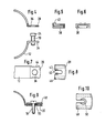
- Fig. 1 illustrates the different effects of the position of a defined hinge point on the movement conditions of the clamping screw when hooking into an elongated hole which is open radially on the inside with respect to the central longitudinal axis of the pipe clamp in a flange opposite the clamping screw at the opening of the pipe clamp.
- the center of the pipe clamp not shown, is located at a distance to the right of the clamping screw shown in each case. This is each articulated on the foot, but in all variants in different ways, and to pivot from the position shown in solid lines by the angle ⁇ to the dashed position when the head of the clamping screw from the radially inner side of the pipe clamp into there open slot is hooked into the opposite flange.
- FIG. 1 The left representation of Fig. 1 corresponds to a pipe clamp, as described in German patent application P 34 36 710.1.
- the right representation of FIG. 1 corresponds to a practical implementation z. 2, and the middle representation of FIG. 1 characterizes the conditions in a pipe clamp according to FIG. 3.
- a tensioning screw 10 the foot of which is screwed into a plate 14 which is articulated on the annular bracket 12 of the pipe clamp, a bracket-shaped part 16 or the like with thread engagement, when pivoting inward about the with 18 be Drawn joint axis on a circular arc, which leads relatively far in the circumferential direction of the ring-shaped pipe clamp bracket, ie in Fig. 1 and 2 relatively far up to the radially inner end of a flange 20 which extends radially inwardly from an enlarged hole 21, is provided radially closed slot 22 into which the head 24 of the clamping screw 10 can be hooked.
- FIG. 1 A counterexample, which corresponds to an embodiment according to German patent application P 34 36 710.1, is shown on the left in FIG. 1.
- the foot of the tensioning screw 10 is screwed into a tab or plate 28, which is articulated at 30 at the free end of a flange at the lower part of a pipe clamp, while the head of the tensioning screw is moved into an open from the inside by a movement from radially inside to radially outside Elongated hole of a flange should be hooked onto the upper part of the pipe clamp.
- the screw head lowers with increasing inclination, i. H. removed from the flange on which it is to be hooked.
- the pivot axis 18 of the joint should be on the side of the center point of the pipe clamp. It can also come close to the central longitudinal axis of the clamping screw. If, in addition, according to FIG. 3 and the middle representation of FIG. 1, the hinge axis intersects the screw axis, the screw length in the inclined position when hooking in must be somewhat larger than in the engagement position shown in dashed lines, but this excess, which is only necessary for the hooking-in process, can normally be found in practice can be tolerated taking into account the then relatively simple design of the pivot bearing.
- joint parts can also, such as. B. in Fig. 2, immediately hooked into each other.
- the joint could be arranged at a greater distance from the opening of the pipe clamp in the bracket.
- FIGS. 4 to 8 An alternative solution to the pipe clamps described so far is shown in FIGS. 4 to 8.
- both a flange 34 carrying the clamping screw 10 and the opposite flange 20 are rigidly connected to the bracket 12.
- the bracket 12 there is no narrow elongated hole in the flange 20, but rather a hole 36 that is so large in cross-section that the screw head 24 can be passed easily.
- the clamping screw 10 could then of course withdraw from the hole 36 without the aid of further measures.
- a washer according to FIGS. 5, 6 and 8, which is specially designed in the example is provided.
- this washer designated 38, has an elongated hole 40 which is open at one end, so that it can be pushed between the flange 20 and the screw head 24 after the screw head 24 has been passed through the hole 36. Then the screw extends shaft through the elongated hole 40, and the screw head 24, which is wider than the elongated hole 40, can no longer retract through the hole 36.
- the washer 38 is formed next to the elongated hole 40 at its open end with two opposite bumps 42, the spacing between which is smaller than the diameter of the screw head 24.
- the bumps 42 are next to the screw head 24 after tightening the clamping screw 10 and prevent the Washer 38 is lost or withdrawn.
- the flange 20 has opposite lateral recesses 44, and the washer 38 is angled laterally around the flange 20, behind it, as can be seen in FIG. 6. It thus leads in the radial direction on the flange 20.
- small lateral lugs 46 shown in FIG. 8 engage in the recesses 44, into which they have previously been snapped.
- the arrangement of the lugs 46 on that edge of the washer 38, at which the elongated hole 40 opens, and the length of the cutouts 44 with respect to the position of the hole 36 allow the washer 38 to be initially radially outward when the pipe clamp is installed withdraw that the screw head 24 can be passed through the hole 36. Thereafter, only the washer 38 needs to be pushed radially inward to lock the pipe clamp closure.
- the washer 48 shown there in longitudinal section and in plan view has a recess 50 in the central region. This is dimensioned so that it is smaller than the hole 36 in the flange 20.
- the recess 50 is partially pressed into the hole 36 by the tensioning screw 10, and the washer 48 is thereby positively held on the flange 20. If the recess 50 is also pronounced on the upper side of the washer 48, it should there be larger in outline than the screw head, so that the arrangement shown in FIG. 9 results in the assembled state.
Landscapes
- Engineering & Computer Science (AREA)
- General Engineering & Computer Science (AREA)
- Mechanical Engineering (AREA)
- Clamps And Clips (AREA)
- Supports For Pipes And Cables (AREA)
- Joints That Cut Off Fluids, And Hose Joints (AREA)
- Load-Engaging Elements For Cranes (AREA)
- Processing Of Terminals (AREA)
- Lasers (AREA)
- Investigating Or Analyzing Materials By The Use Of Magnetic Means (AREA)
Priority Applications (1)
| Application Number | Priority Date | Filing Date | Title |
|---|---|---|---|
| AT86116048T ATE50347T1 (de) | 1985-12-07 | 1986-11-20 | Rohrschelle. |
Applications Claiming Priority (2)
| Application Number | Priority Date | Filing Date | Title |
|---|---|---|---|
| DE3543383 | 1985-12-07 | ||
| DE3543383A DE3543383C2 (de) | 1985-12-07 | 1985-12-07 | Rohrschelle |
Related Child Applications (1)
| Application Number | Title | Priority Date | Filing Date |
|---|---|---|---|
| EP89101504.2 Division-Into | 1989-01-28 |
Publications (3)
| Publication Number | Publication Date |
|---|---|
| EP0225515A2 true EP0225515A2 (fr) | 1987-06-16 |
| EP0225515A3 EP0225515A3 (en) | 1987-11-11 |
| EP0225515B1 EP0225515B1 (fr) | 1990-02-07 |
Family
ID=6287962
Family Applications (1)
| Application Number | Title | Priority Date | Filing Date |
|---|---|---|---|
| EP86116048A Expired - Lifetime EP0225515B1 (fr) | 1985-12-07 | 1986-11-20 | Collier de serrage |
Country Status (5)
| Country | Link |
|---|---|
| EP (1) | EP0225515B1 (fr) |
| JP (2) | JPH0823395B2 (fr) |
| AT (1) | ATE50347T1 (fr) |
| DE (3) | DE3543383C2 (fr) |
| ES (1) | ES2013706B3 (fr) |
Cited By (3)
| Publication number | Priority date | Publication date | Assignee | Title |
|---|---|---|---|---|
| FR2631678A1 (fr) * | 1988-05-21 | 1989-11-24 | Flamco Bv | Collier de fixation pour tubes, a crampon de maintien de vis filetee, et un tel crampon |
| EP0471989A1 (fr) * | 1990-08-23 | 1992-02-26 | "TOGE-DÜBEL" A. Gerhard GmbH | Collier de serrage |
| EP1515074A1 (fr) * | 2003-09-09 | 2005-03-16 | Mefa Befestigungs- und Montagesysteme GmbH | Dispositif de raccordement de deux pièces de bride |
Families Citing this family (4)
| Publication number | Priority date | Publication date | Assignee | Title |
|---|---|---|---|---|
| DE4015404C2 (de) * | 1990-03-26 | 1994-01-05 | Maechtle Woehler Margot | Rohrschelle |
| DE9215190U1 (de) * | 1992-11-07 | 1992-12-24 | FKB Feinwerktechnik und Kunststoffverarbeitungsgesellschaft mbH, 7238 Oberndorf | Rohrschelle |
| DE4433640A1 (de) * | 1994-09-21 | 1996-03-28 | Sina Befestigungssysteme Gmbh | Rohrschelle |
| FR3159823B1 (fr) * | 2024-03-01 | 2026-04-24 | Caillau | Collier de serrage à oreille de serrage |
Family Cites Families (11)
| Publication number | Priority date | Publication date | Assignee | Title |
|---|---|---|---|---|
| US2368929A (en) * | 1944-01-17 | 1945-02-06 | James T King | Quick-coupling clamp |
| US2941273A (en) * | 1958-08-18 | 1960-06-21 | Specialty Products Corp | Clamp |
| GB1033659A (en) * | 1962-07-02 | 1966-06-22 | Aeroquip Ag | A band clamp |
| DE6900634U (de) * | 1969-01-09 | 1969-06-12 | Erich Schlemper | Insbesondere als schlauchklemme zu verwendende ringfoermige spannvorrichtung |
| JPS50154500U (fr) * | 1974-06-07 | 1975-12-22 | ||
| JPS54182933U (fr) * | 1978-06-16 | 1979-12-25 | ||
| JPS5635974U (fr) * | 1979-08-29 | 1981-04-07 | ||
| JPS56101283U (fr) * | 1979-12-29 | 1981-08-08 | ||
| DE3346423A1 (de) * | 1983-02-23 | 1984-08-23 | Toge-Dübel A.Gerhard GmbH, 8500 Nürnberg | Rohrschelle |
| DE3308459A1 (de) * | 1983-03-10 | 1984-09-13 | Peter Dipl.-Ing. 8500 Nürnberg Wölfel | Rohrschelle |
| DE3436710C2 (de) * | 1984-10-06 | 1986-09-11 | Franz 6200 Wiesbaden Müller | Rohrschelle |
-
1985
- 1985-12-07 DE DE3543383A patent/DE3543383C2/de not_active Expired - Lifetime
-
1986
- 1986-11-20 DE DE8989101504T patent/DE3675397D1/de not_active Expired - Lifetime
- 1986-11-20 DE DE8686116048T patent/DE3668975D1/de not_active Expired - Lifetime
- 1986-11-20 AT AT86116048T patent/ATE50347T1/de not_active IP Right Cessation
- 1986-11-20 ES ES86116048T patent/ES2013706B3/es not_active Expired - Lifetime
- 1986-11-20 EP EP86116048A patent/EP0225515B1/fr not_active Expired - Lifetime
- 1986-12-08 JP JP61290648A patent/JPH0823395B2/ja not_active Expired - Fee Related
-
1995
- 1995-08-04 JP JP7200008A patent/JP2612156B2/ja not_active Expired - Fee Related
Cited By (3)
| Publication number | Priority date | Publication date | Assignee | Title |
|---|---|---|---|---|
| FR2631678A1 (fr) * | 1988-05-21 | 1989-11-24 | Flamco Bv | Collier de fixation pour tubes, a crampon de maintien de vis filetee, et un tel crampon |
| EP0471989A1 (fr) * | 1990-08-23 | 1992-02-26 | "TOGE-DÜBEL" A. Gerhard GmbH | Collier de serrage |
| EP1515074A1 (fr) * | 2003-09-09 | 2005-03-16 | Mefa Befestigungs- und Montagesysteme GmbH | Dispositif de raccordement de deux pièces de bride |
Also Published As
| Publication number | Publication date |
|---|---|
| ES2013706B3 (es) | 1990-06-01 |
| DE3668975D1 (de) | 1990-03-15 |
| JPS62196484A (ja) | 1987-08-29 |
| DE3543383C2 (de) | 1993-10-07 |
| ATE50347T1 (de) | 1990-02-15 |
| JP2612156B2 (ja) | 1997-05-21 |
| EP0225515A3 (en) | 1987-11-11 |
| JPH0823395B2 (ja) | 1996-03-06 |
| DE3675397D1 (de) | 1990-12-06 |
| DE3543383A1 (de) | 1987-06-11 |
| JPH08105576A (ja) | 1996-04-23 |
| EP0225515B1 (fr) | 1990-02-07 |
Similar Documents
| Publication | Publication Date | Title |
|---|---|---|
| EP0327990B1 (fr) | Dispositif de liaison, en particulier pour un siège d'avion | |
| DE69006985T2 (de) | Befestigungseinrichtung. | |
| DE3439418C2 (de) | Rohrschelle | |
| DE69004548T2 (de) | Schnell montierbare mutter. | |
| EP0280966B1 (fr) | Pièces de guidage pour une machine de traitement de récipients | |
| DE2709272C2 (de) | Schraubklemme | |
| EP0253819A1 (fr) | Moule de soufflage a longueur reglable. | |
| DE2405262A1 (de) | Spannschraube | |
| DE10024834A1 (de) | Spannring | |
| DE69401399T2 (de) | Rohrschelle | |
| DE3601127C2 (de) | Lasthängevorrichtung mit verbessertem Hakenbolzen | |
| DE4237674A1 (de) | Rohrschelle | |
| CH691919A5 (de) | Schnellöseklemmenanordnung. | |
| EP0567821B1 (fr) | Collier de serrage | |
| EP0225515A2 (fr) | Collier de serrage | |
| DE3436710C2 (de) | Rohrschelle | |
| EP0225516B1 (fr) | Collier de serrage | |
| EP0319521B1 (fr) | Collier de serrage | |
| EP0195914A2 (fr) | Raccord pour tuyau ou manche | |
| DE2033425A1 (de) | Vorrichtung zum Ausrichten von Korpern | |
| EP0462052B1 (fr) | Collier de serrage pour tuyau | |
| DE4341422A1 (de) | Topfscharnier | |
| DE1284608B (de) | Teleskopartig ausziehbarer Schalungstraeger | |
| CH658290A5 (de) | Stuetzvorrichtung fuer ein schalungselement. | |
| DE3306860A1 (de) | Vorrichtung zur befestigung von schienen auf stahlschwellen |
Legal Events
| Date | Code | Title | Description |
|---|---|---|---|
| PUAI | Public reference made under article 153(3) epc to a published international application that has entered the european phase |
Free format text: ORIGINAL CODE: 0009012 |
|
| AK | Designated contracting states |
Kind code of ref document: A2 Designated state(s): AT CH DE ES FR GB IT LI NL |
|
| PUAL | Search report despatched |
Free format text: ORIGINAL CODE: 0009013 |
|
| AK | Designated contracting states |
Kind code of ref document: A3 Designated state(s): AT CH DE ES FR GB IT LI NL |
|
| 17P | Request for examination filed |
Effective date: 19871126 |
|
| 17Q | First examination report despatched |
Effective date: 19890107 |
|
| GRAA | (expected) grant |
Free format text: ORIGINAL CODE: 0009210 |
|
| AK | Designated contracting states |
Kind code of ref document: B1 Designated state(s): AT CH DE ES FR GB IT LI NL |
|
| REF | Corresponds to: |
Ref document number: 50347 Country of ref document: AT Date of ref document: 19900215 Kind code of ref document: T |
|
| REF | Corresponds to: |
Ref document number: 3668975 Country of ref document: DE Date of ref document: 19900315 |
|
| ITF | It: translation for a ep patent filed | ||
| ET | Fr: translation filed | ||
| GBT | Gb: translation of ep patent filed (gb section 77(6)(a)/1977) | ||
| PLBE | No opposition filed within time limit |
Free format text: ORIGINAL CODE: 0009261 |
|
| STAA | Information on the status of an ep patent application or granted ep patent |
Free format text: STATUS: NO OPPOSITION FILED WITHIN TIME LIMIT |
|
| 26N | No opposition filed | ||
| ITTA | It: last paid annual fee | ||
| REG | Reference to a national code |
Ref country code: GB Ref legal event code: IF02 |
|
| PGFP | Annual fee paid to national office [announced via postgrant information from national office to epo] |
Ref country code: AT Payment date: 20021114 Year of fee payment: 17 |
|
| PGFP | Annual fee paid to national office [announced via postgrant information from national office to epo] |
Ref country code: GB Payment date: 20021115 Year of fee payment: 17 |
|
| PGFP | Annual fee paid to national office [announced via postgrant information from national office to epo] |
Ref country code: NL Payment date: 20021118 Year of fee payment: 17 |
|
| PGFP | Annual fee paid to national office [announced via postgrant information from national office to epo] |
Ref country code: ES Payment date: 20021119 Year of fee payment: 17 |
|
| PGFP | Annual fee paid to national office [announced via postgrant information from national office to epo] |
Ref country code: FR Payment date: 20021128 Year of fee payment: 17 |
|
| PGFP | Annual fee paid to national office [announced via postgrant information from national office to epo] |
Ref country code: CH Payment date: 20021129 Year of fee payment: 17 |
|
| PGFP | Annual fee paid to national office [announced via postgrant information from national office to epo] |
Ref country code: DE Payment date: 20030125 Year of fee payment: 17 |
|
| PG25 | Lapsed in a contracting state [announced via postgrant information from national office to epo] |
Ref country code: GB Free format text: LAPSE BECAUSE OF NON-PAYMENT OF DUE FEES Effective date: 20031120 Ref country code: AT Free format text: LAPSE BECAUSE OF NON-PAYMENT OF DUE FEES Effective date: 20031120 |
|
| PG25 | Lapsed in a contracting state [announced via postgrant information from national office to epo] |
Ref country code: ES Free format text: LAPSE BECAUSE OF NON-PAYMENT OF DUE FEES Effective date: 20031121 |
|
| PG25 | Lapsed in a contracting state [announced via postgrant information from national office to epo] |
Ref country code: LI Free format text: LAPSE BECAUSE OF NON-PAYMENT OF DUE FEES Effective date: 20031130 Ref country code: CH Free format text: LAPSE BECAUSE OF NON-PAYMENT OF DUE FEES Effective date: 20031130 |
|
| PG25 | Lapsed in a contracting state [announced via postgrant information from national office to epo] |
Ref country code: NL Free format text: LAPSE BECAUSE OF NON-PAYMENT OF DUE FEES Effective date: 20040601 |
|
| PG25 | Lapsed in a contracting state [announced via postgrant information from national office to epo] |
Ref country code: DE Free format text: LAPSE BECAUSE OF NON-PAYMENT OF DUE FEES Effective date: 20040602 |
|
| GBPC | Gb: european patent ceased through non-payment of renewal fee |
Effective date: 20031120 |
|
| REG | Reference to a national code |
Ref country code: CH Ref legal event code: PL |
|
| PG25 | Lapsed in a contracting state [announced via postgrant information from national office to epo] |
Ref country code: FR Free format text: LAPSE BECAUSE OF NON-PAYMENT OF DUE FEES Effective date: 20040730 |
|
| NLV4 | Nl: lapsed or anulled due to non-payment of the annual fee |
Effective date: 20040601 |
|
| REG | Reference to a national code |
Ref country code: FR Ref legal event code: ST |
|
| REG | Reference to a national code |
Ref country code: ES Ref legal event code: FD2A Effective date: 20031121 |
|
| PG25 | Lapsed in a contracting state [announced via postgrant information from national office to epo] |
Ref country code: IT Free format text: LAPSE BECAUSE OF NON-PAYMENT OF DUE FEES;WARNING: LAPSES OF ITALIAN PATENTS WITH EFFECTIVE DATE BEFORE 2007 MAY HAVE OCCURRED AT ANY TIME BEFORE 2007. THE CORRECT EFFECTIVE DATE MAY BE DIFFERENT FROM THE ONE RECORDED. Effective date: 20051120 |