EP0227412A2 - Dispositif de serrure de porte pour une automobile - Google Patents
Dispositif de serrure de porte pour une automobile Download PDFInfo
- Publication number
- EP0227412A2 EP0227412A2 EP86309802A EP86309802A EP0227412A2 EP 0227412 A2 EP0227412 A2 EP 0227412A2 EP 86309802 A EP86309802 A EP 86309802A EP 86309802 A EP86309802 A EP 86309802A EP 0227412 A2 EP0227412 A2 EP 0227412A2
- Authority
- EP
- European Patent Office
- Prior art keywords
- operating plate
- door
- key
- engaging
- switch
- Prior art date
- Legal status (The legal status is an assumption and is not a legal conclusion. Google has not performed a legal analysis and makes no representation as to the accuracy of the status listed.)
- Granted
Links
Images


Classifications
-
- E—FIXED CONSTRUCTIONS
- E05—LOCKS; KEYS; WINDOW OR DOOR FITTINGS; SAFES
- E05B—LOCKS; ACCESSORIES THEREFOR; HANDCUFFS
- E05B77/00—Vehicle locks characterised by special functions or purposes
- E05B77/22—Functions related to actuation of locks from the passenger compartment of the vehicle
- E05B77/24—Functions related to actuation of locks from the passenger compartment of the vehicle preventing use of an inner door handle, sill button, lock knob or the like
- E05B77/28—Functions related to actuation of locks from the passenger compartment of the vehicle preventing use of an inner door handle, sill button, lock knob or the like for anti-theft purposes, e.g. double-locking or super-locking
-
- E—FIXED CONSTRUCTIONS
- E05—LOCKS; KEYS; WINDOW OR DOOR FITTINGS; SAFES
- E05B—LOCKS; ACCESSORIES THEREFOR; HANDCUFFS
- E05B47/00—Operating or controlling locks or other fastening devices by electric or magnetic means
- E05B47/06—Controlling mechanically-operated bolts by electro-magnetically-operated detents
- E05B47/0603—Controlling mechanically-operated bolts by electro-magnetically-operated detents the detent moving rectilinearly
-
- B—PERFORMING OPERATIONS; TRANSPORTING
- B60—VEHICLES IN GENERAL
- B60R—VEHICLES, VEHICLE FITTINGS, OR VEHICLE PARTS, NOT OTHERWISE PROVIDED FOR
- B60R25/00—Fittings or systems for preventing or indicating unauthorised use or theft of vehicles
- B60R25/01—Fittings or systems for preventing or indicating unauthorised use or theft of vehicles operating on vehicle systems or fittings, e.g. on doors, seats or windscreens
- B60R25/04—Fittings or systems for preventing or indicating unauthorised use or theft of vehicles operating on vehicle systems or fittings, e.g. on doors, seats or windscreens operating on the propulsion system, e.g. engine or drive motor
-
- B—PERFORMING OPERATIONS; TRANSPORTING
- B60—VEHICLES IN GENERAL
- B60R—VEHICLES, VEHICLE FITTINGS, OR VEHICLE PARTS, NOT OTHERWISE PROVIDED FOR
- B60R25/00—Fittings or systems for preventing or indicating unauthorised use or theft of vehicles
- B60R25/10—Fittings or systems for preventing or indicating unauthorised use or theft of vehicles actuating a signalling device
- B60R25/1001—Alarm systems associated with another car fitting or mechanism, e.g. door lock or knob, pedals
-
- E—FIXED CONSTRUCTIONS
- E05—LOCKS; KEYS; WINDOW OR DOOR FITTINGS; SAFES
- E05B—LOCKS; ACCESSORIES THEREFOR; HANDCUFFS
- E05B81/00—Power-actuated vehicle locks
- E05B81/54—Electrical circuits
- E05B81/56—Control of actuators
- E05B81/58—Control of actuators including time control, e.g. for controlling run-time of electric motors
-
- E—FIXED CONSTRUCTIONS
- E05—LOCKS; KEYS; WINDOW OR DOOR FITTINGS; SAFES
- E05B—LOCKS; ACCESSORIES THEREFOR; HANDCUFFS
- E05B81/00—Power-actuated vehicle locks
- E05B81/54—Electrical circuits
- E05B81/64—Monitoring or sensing, e.g. by using switches or sensors
-
- E—FIXED CONSTRUCTIONS
- E05—LOCKS; KEYS; WINDOW OR DOOR FITTINGS; SAFES
- E05B—LOCKS; ACCESSORIES THEREFOR; HANDCUFFS
- E05B47/00—Operating or controlling locks or other fastening devices by electric or magnetic means
- E05B47/0001—Operating or controlling locks or other fastening devices by electric or magnetic means with electric actuators; Constructional features thereof
- E05B47/0002—Operating or controlling locks or other fastening devices by electric or magnetic means with electric actuators; Constructional features thereof with electromagnets
- E05B47/0003—Operating or controlling locks or other fastening devices by electric or magnetic means with electric actuators; Constructional features thereof with electromagnets having a movable core
- E05B47/0004—Operating or controlling locks or other fastening devices by electric or magnetic means with electric actuators; Constructional features thereof with electromagnets having a movable core said core being linearly movable
-
- E—FIXED CONSTRUCTIONS
- E05—LOCKS; KEYS; WINDOW OR DOOR FITTINGS; SAFES
- E05B—LOCKS; ACCESSORIES THEREFOR; HANDCUFFS
- E05B81/00—Power-actuated vehicle locks
- E05B81/02—Power-actuated vehicle locks characterised by the type of actuators used
- E05B81/04—Electrical
- E05B81/08—Electrical using electromagnets or solenoids
-
- E—FIXED CONSTRUCTIONS
- E05—LOCKS; KEYS; WINDOW OR DOOR FITTINGS; SAFES
- E05B—LOCKS; ACCESSORIES THEREFOR; HANDCUFFS
- E05B85/00—Details of vehicle locks not provided for in groups E05B77/00 - E05B83/00
- E05B85/20—Bolts or detents
- E05B85/24—Bolts rotating about an axis
- E05B85/243—Bolts rotating about an axis with a bifurcated bolt
-
- Y—GENERAL TAGGING OF NEW TECHNOLOGICAL DEVELOPMENTS; GENERAL TAGGING OF CROSS-SECTIONAL TECHNOLOGIES SPANNING OVER SEVERAL SECTIONS OF THE IPC; TECHNICAL SUBJECTS COVERED BY FORMER USPC CROSS-REFERENCE ART COLLECTIONS [XRACs] AND DIGESTS
- Y10—TECHNICAL SUBJECTS COVERED BY FORMER USPC
- Y10T—TECHNICAL SUBJECTS COVERED BY FORMER US CLASSIFICATION
- Y10T292/00—Closure fasteners
- Y10T292/08—Bolts
- Y10T292/1043—Swinging
- Y10T292/1044—Multiple head
- Y10T292/1045—Operating means
- Y10T292/1047—Closure
-
- Y—GENERAL TAGGING OF NEW TECHNOLOGICAL DEVELOPMENTS; GENERAL TAGGING OF CROSS-SECTIONAL TECHNOLOGIES SPANNING OVER SEVERAL SECTIONS OF THE IPC; TECHNICAL SUBJECTS COVERED BY FORMER USPC CROSS-REFERENCE ART COLLECTIONS [XRACs] AND DIGESTS
- Y10—TECHNICAL SUBJECTS COVERED BY FORMER USPC
- Y10T—TECHNICAL SUBJECTS COVERED BY FORMER US CLASSIFICATION
- Y10T70/00—Locks
- Y10T70/60—Systems
- Y10T70/625—Operation and control
- Y10T70/65—Central control
Definitions
- This invention relates to a door lock device for automobile.
- Door lock device for automobiles generally includes a cylinder lock adapted for locking and unlocking the door from outside thereof by a key which also serves as engine key, and a manual lock operated from inside of the door for locking and unlocking the door.
- Car burglars usually pull up the manual lock using a wire or a thin plate for unlocking the door of the car and, thereafter, start the engine by directly connecting the ignitor, starter motor and the like with the battery.
- the present invention contemplates the provision of a door lock device which permits the start of the engine only when the door is unlocked with the use of a key. As a consequence, it is no longer necessary for the door key to function also as an engine key for starting the engine, i.e. providing an engine start switch on the front panel is sufficient.
- a door lock device for automobile having an engine starting circuit, a door frame and a door swingeably supported to the door frame, said device comprising: an operating plate supported in the door and moveable between upper and lower positions; engaging means engageable with said operating plate and moveable between first and second positions such that when said engaging means is displaced from the first to second position the operating plate is moved from the lower to upper position, but when the operating plate is moved from the lower to upper position the engaging means in the first position is disengaged therefrom and is remained unmoved; actuating means for moving said enging means from the first to second position; a hook member provided in the door frame; latch means provided in the door and capable of engaging with said hook member when the door is closed and of disengaging from said hook member when the door is opened; an engaging portion provided in said operating plate and engageable with said latch means to prevent said latch means from disengaging from said strike when said operating plate is in the lower position and disengageable from said latch means to permit said latch means to disengage from said
- Figs. 1 and 2 designated generally as 1 is an automobile having a body 2 and a door 3 swingably secured to the body 2 and provided with a door handle 4 and a cylinder lock 6.
- an inner door handle 5 operated for opening and closing the door 1
- a manual lock 7 for locking and unlocking the door 3.
- the reference numeral 8 designates an engine switch for starting and stopping the engine.
- the engine switch 8 in this embodiment is operable as such without using an engine key. However, if desired, the engine switch may be arranged so that it is actuated in the conventional manner by a key used for opening the cylinder lock 6.
- the door 3 accomodates the main structure of door locking device according to the present invention.
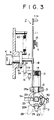
- Figs. 3 and 4 depict one preferred embodiment of the door lock device of this invention.
- the lock device generally designated as 7, includes an operating plate 11 generally vertically slidably supported in the door 3.
- the operating plate 11 extends upward out of the door 3 and is provided at its top end with a lug 11a arranged to make easy the downward and upward movement, by hands, of the operating plate 11 between upper and lower positions.
- Designated as 15 is a coil spring one end of which is secured to the operating plate 11 with the other end being fixed to the door 3 so that the operating plate 11 may be maintained in either the upper position or the lower position by the action of the coil spring 15.
- the operating plate 11 has an protruded portion 11b adapted for engaging with a switch S1 fixed to the door 3 so that the switch S1 is maintained in the ON and OFF positions when the operating plate 11 is in the lower and upper positions, respectively.
- the operating plate 11 may also be upwardly moved by rotation of the key K inserted in the cylinder lock 6.
- the cylinder lock 6 is connected to a rotating plate 16 so that the rotating plate 16 may be rotated with the key K.
- the rotating plate 16 has a center shaft 17 about which the plate 16 is rotated and to which a lever 18 is fixedly secured.
- the lever 18 is engageable with an indented portion 11c of the operating plate 11 so that the rotation of the lever 18 in one direction (in the direction shown by the arrow B in Fig. 4) causes the operating plate 11 to move upward.
- the indented portion 11c of the operating plate 11 has a length sufficient enough to allow the lever 18 to disengage therefrom when the lever 18 is rotated in the other direction (counter clockwise in Fig. 4).
- a switch S2 is secured at a position adjacent to the rotating plate 16.
- the plate 16 is furnished with a magnet 19 so that the switch S2 is turned ON when the magnet 19 is located at a position adjacent thereto.
- the engaging bar 12 In the lower portion of the operating plate 11, there is mounted a case 13 within which an engaging bar 12 is accomodated.
- the lower end of the engaging bar 12 is protruded from the lower open-ended portion of the case 13 and is shaped so as to engage with a first groove 25a provided in the periphery of a rotating member 25.
- the upper end of the engaging bar 12 is connected to a lower end of a spring 14 whose upper end is fixed to the ceiling of the case 13.
- the engaging bar 12 can be in pressure contact with the outer periphery (inclusive of the first groove 25a) of the rotating member 25 when the operating plate 11 is in the lower position.
- the engaging bar 12 When the operating plate 11 is in the upper position, the engaging bar 12 is disengaged from the first groove 25a of the rotating member 25 to permit the rotation thereof.
- the rotating member 25 is also provided with a second groove 25b with which one end portion of a rocking lever 23 is engageable.
- the rocking lever 23 is rotatably secured about a shaft 24.
- the other end of the rocking lever 23 is rotatably linked with an operating rod of the door handles (Fig. 1) by means of a hinge 22 so that the rocking lever 23 is rotated about the shaft 24 and engageable with and disengaged from the second groove 25b of the rotating member 25 in response to the operation of the outer and inner door handles 4 and 5.
- the rocking lever 23 is normally biased in the clockwise direction as seen in Fig. 4 by any suitable means.
- the rotating member 25 is rotatably supported to the door 3 by any suitable means (not shown) and is rotated about its axis 27 in response to the swing of the door 3 in a manner known per se. That is, a U-shaped engaging plate or latch 28 is secured to the axis 27 at a position opposite to the rotating member 25 for rotation therewith.
- the inner curved portion of the U-shaped engaging plate is so shaped as to engage with a hook member or strike 29 fixed to the car body frame 2 and to cause the engaging plate 28 to rotate when the door is opened or closed.
- one of the legs of the U-shaped engaging plate 28 is capable of being inserted into the hook member 29. As best seen from Fig.
- the engaging plate 28 is rotated because of the engagement between the hook member 29 and the leg of the engaging plate 28 as shown in the phantom line.
- the engaging plate 28 is disengaged from the hook 29 and is oriented in the sideways position as shown in the solid line in Fig. 5.
- the engaging plate 28 is brought into engagement with and is guided by the hook 29 and, thus, is rotated about the axis 27.
- Designated as 30 is a coil spring to maintain the engaging plate 28 either in the vertical position as shown by phantom line in Fig. 3 or in the sideways position as shown in the solid line in Fig. 5.
- a magnet 26 is mounted on the rotating member 25 and is capable of actuating a switch S3 ON and OFF.
- the above-described door lock device operates as follows.
- the lever 18 is rotated in the direction shown by the arrow B in Fig. 4 against the compressive force of the spring 20.
- the operating plate 11 which is in engagement with the lever 18 at the indented portion 11c, is displaced from the lower position to the upper position and maintained at that position by the action of the coil spring 15 as shown in Figs. 6 and 7.
- the switches S1 and S2 are turned OFF and ON, respectively.
- the turning of the switch S2 to ON position causes the power source circuit of the engine starting circuit (not shown) to be closed, so that the engine is ready for starting upon turning the engine switch 8 (Fig. 2) ON.
- the lever is rotated by the action of the spring 20 to the original position together with the key K as shown by the phantom line in Fig. 7, making the switch S2 OFF.
- the lever 18 is disengaged therefrom so that the operating plate 11 is maintained in the upper position by the action of the spring 15. Since the switch S2 is connected to a a relay of a self-holding circuit (not shown), the power source circuit for the engine starting circuit is maintained in a closed state even when the switch S2 is turned OFF.
- the lug 11a is pulled up. This causes the disengagement of the engaging bar 12 from the first groove 25a of the rotating member 25.
- the lever 23 is disengaged from the second groove 25b to permit the rotation of the rotating member 25.
- the door is then opened and the driver gets off the car.
- the door lock device is in the state as shown in Figs. 6 and 7 (The rotating plate 16 is in the state shown by the phantom line in Fig. 7).
- the door 3 cannot be opened because the U-shaped engaging plate 28 is maintained in engagement with the hook 29. Moreover, even if someone can move the operating plate 11 without using the key K and can open the door 3, turning of the engine switch 8 cannot start the engine because the switch S2 is maintained in the OFF position and the power source circuit for the engine starting circuit is remained in the open state. Thus, it is not necessary that the engine switch 8 (Fig. 2) be of a type which is actuated with the use of the door key K.
- Fig. 8 illustrates wave forms showing the action of the switches S1 to S3.
- the switches S1 to S3 are in ON, OFF and ON positions, respectively.
- the switch S2 is turned ON and the switch S1 is turned OFF as a result of the unlocking the door 3.
- This causes the power source circuit of the engine starting circuit to be closed.
- the power source circuit is remained closed until the opened door with its operating plate 11 being in the lower position is closed.
- the switch S2 is turned OFF when the key K is released.
- the switch S3 When the door 3 is opened at time point t2, the switch S3 is turned OFF. The driver gets on the car and closes the door 3 at time point t3. This causes the switch S3 to be turned ON. The operating plate 11 is pushed down for locking at time poit t4, so that the switch S1 is turned ON.
- the operating plate 11 In getting off the car, the operating plate 11 is pulled upward at time point t5, thereby turning the switch S1 OFF. The door is opened at time point t6, rendering the switch S3 OFF. Then the operating plate 11 is lowered to the lower position at time point t7 to turn the switch S1 ON. When the door is closed, the switch S3 is turned ON with the power source circuit for the engine starting circuit being opened.
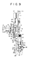
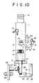
- FIG. 9 and 10 An alternate embodiment according to the present invention is illustrated in Figs. 9 and 10 in which the same reference numerals designate similar component parts.
- the door lock device in this variant likewise in the device shown hereinabove with reference to Figs. 4-7, includes an operating plate 11, an engaging bar 12, a rotating member 25 having a groove 25a engageable with the engaging bar 12, a rocking lever 23 engageable with a second groove 25b of the rotating member 25, a U-shaped engaging plate 28 operatively connected with the rotating member 25 and cooperable with a hook member 29 for rotation of the rotating member 25.
- the construction and function of these elements are the same as those in the foregoing embodiment and the explanation thereof is not repeated here.
- the door lock device in this embodiment includes a solenoid 31 having a plunger 32 and operating plate member 33 fixed to the plunger 32 for vertical movement therewith.
- the solenoid 31 in this embodiment is actuated by remote control. For example, by turning to an ON position a switch provided in a pocket portable controller (not shown) carried by the driver, laser signals or electrical signals with a predetermined pulse code are generated.
- the controller in this embodiment is preferably a laser key.
- the laser signals are read out by a control unit (not shown) provided in the car and if the read out signals are the same as memories stored therein, a command is supplied to the solenoid for the actuation thereof.
- Designated as 34 is a stopper to prevent the plunger 32 from falling from the solenoid 31 during its non-energized state.
- the operating plate 11 in this variant is provided with a protruded portion 11d which serves to function similar to the indented portion 11c of the foregoing embodiment.
- the operating plate member 33 operatively connected to the solenoid 31 is provided with a projection 33a arranged for engagement with the protruded portion 11d of the operating plate 11 such that when the solenoid is actuated to raise the member 33 from a lower location (as shown in Fig. 9) to an upper location, the projection 33a is engaged by the protruded portion 11d to displace the operating plate 11 from a lower position (as shown in Fig. 9) to an upper position, but when the operating plate 11 is displaced from the lower position to upper position the protruded portion 11d is disengaged from the projection 33a.
- the operating plate member 33 has an additional projection 33b adapted to engage with a switch S2 fixed within the door 3.
- the switch S2 is turned ON when the operating plate member 33 is moved to the upper location.
- the switch S2 functions in the same manner as in the above first embodiment; i.e. the power source circuit for the engine starting circuit is actuated only when the switch S2 is turned ON.
- Fig. 11 is a wave form similar to Fig. 8.
- the switches S1 to S3 are in ON, OFF and ON positions, respectively.
- the solenoid 31 is actuated to move the operating plate member 33 to the upper location, thereby displacing the operating plate 11 to the upper position.
- the switch S2 is turned ON and the switch S1 is turned OFF. This causes the door to be openable and the power source circuit of the engine starting circuit to be closed. The power source circuit is remained closed until the opened door with its operating plate 11 being in the lower position is closed.
- the switch S3 When the door 3 is opened at time point t2, the switch S3 is turned OFF. The driver gets on the car and closes the door 3 at time point t3. This causes the switch S3 to be turned ON. The operating plate 11 is pushed down for locking at time poit t4, so that the switch S1 is turned ON. This also causes the switch S2 to the OFF position.
- the operating plate 11 In getting off the car, the operating plate 11 is pulled upward at time point t5, thereby turning the switch S1 OFF. The door is opened at time point t6, rendering the switch S3 OFF. Then the operating plate 11 is lowered to the lower position at time point t7 to turn the switch S1 ON. When the door is closed, the switch S3 is turned ON with the power source circuit for the engine starting circuit being opened.
- the lock device shown in Figs. 9 and 10 is arranged so that the door may also be unlocked with a key K when the solenoid 31 is not actuated due to, for example, an electric failure in the laser key or control unit.
- a cylinder lock 6 is provided in the door similar to the embodiment shown in Fig. 3.
- a rotating plate 16 is connected to the cylinder lock 6 so that the rotating plate 16 may be rotated with the key K.
- the rotating plate 16 has a center shaft 17a about which the plate 16 is rotated and to which a lever 18 is fixedly secured, so that the lever 18 may be rotated by turning the key K inserted into the key hole of the cylinder lock 6.
- a second operating plate 41 is provided adjacent to the operating plate member 33.
- the second operating plate has an indented portion 41b with which the lever 18 is continually engaged so that the rotation of the lever 18 always causes the second operating plate 41 to move downward or upward depending on the direction of the rotation of the lever 18.
- the second operating plate 41 is maintained in either an upper or lower position by means of a coil spring 42 mounted on the rotating plate 16.
- Designated as 41a is a stopper.
- the second operating plate 41 is fixedly provided with a shaft 44 to which a rotor plate 43 is rotatably supported and with a protrusion 47 which is inserted through a guide slot 48 provided in the rotor plate 43.
- the rotor plate 43 is moved up and down together with the second operating plate 41.
- the rotor plate 43 is rotated by the action of a spring 46 mounted on the protrusion 47.
- One leg of the spring 46 is pressure engagement with a projection 50 of the rotor plate 43 with the other leg being with a projection 49 of the second operating plate 41, so that the rotor plate 43 is normally urged to rotate in the direction shown by the arrow E in Fig. 12.
- a stopper 51 is disposed in the door 3 at a position so that the rotor plate 43 is engaged by and is in pressure contact with the stopper 51 when the second operating plate is in the upper position.
- the rotor plate 43 has a projection 45 engageable with an indented portion 33c of the operating plate member 33.
- the reference numeral 19 designates a magnet which actuates a switch S4 when it is positioned adjacent thereto, i.e. when the rotating plate 16 is rotated to such a location as to render the second operating plate 41 in the lower position.
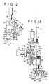
- Figs. 9 and 12 show the state in which the door is closed and locked
- the lever 18 is rotated in the direction shown by the arrow D.
- the second operating plate 41 is displaced, together with the rotor plate 43, to the lower position.
- This causes the disengagement between the stopper 51 and the rotor plate 43 so that the rotor plate 43 is rotated in the direction shown by the arrow E by the action of the spring 46.
- the projection 45 of the rotor plate 43 is engaged with the indented portion 33c of the operating plate member 33.
- the switch S4 is turned ON.
- the key K is manually rotated in the direction reverse to the arrow C.
- the lever 18 is rotated in the direction opposite to the arrow D in Fig. 12, causing the displacement of the second operating plate 41 from the lower position (as shown in Fig. 15) to the upper position as shown in Figs. 13 and 14.
- the engaging plate member 33 Due to the engagement between the projection 45 and the indented portion 33c, the engaging plate member 33 is also displaced to the upper position.
- the operating plate 11 is moved to the upper position due to the engagement between the projection 33a and the protrusion 11d. This state is as shown in Figs. 13 and 14.
- the switch S4 is turned OFF and the door is unlocked and becomes openable.
- the rotor plate 43 is brought into engagement with the stopper 51 and further upward movement of the second operating plate 41 causes the projection 45 to be disengaged from the indented portion 33c as shown in Fig. 16.
- a timer By connecting a timer to the switches and by providing a reset button and a cautionary/alarm sound generator to the timer, it is possible to produce a cautionary or alarm sound when the door is unlocked by manually turning the key K rather than by automatic actuation of the solenoid.
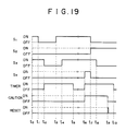
- One such an embodiment is shown in Figs. 17 through 19 wherein the timer is arranged to be actuated either when the switch S4 is turned ON in the conditions in which the switches S1 and S3 are both ON positions or when the switch S3 is turned OFF in the conditions in which the switch S1 is in the OFF position and wherein the alarm is actuated only when the timer is actuated and the switch S4 is in the ON position.
- Such an arrangement may be easily prepared by using suitable conventional circuits.
- the door is in the closed and locked state.
- the switch S4 is turned ON to start the actuation of the timer for a predetermined period, e.g. 20 sec.
- the caution generator is actuated upon the actuation of the timer and continues to generate a cautionary sound for the predetermined period or until the reset button is pushed (t4). If the reset button is failed to be pushed, the cautionary sound is stopped after the lapse of the predetermined period (t4) but, instead, an alarm sound is generated (t6).
- the key K is turned to the reverse direction as shown in Fig. 16, at t3 the door is opened, at t5 the door is closed and at at t7 the operating plate is displaced to the lower position to lock the door.
- Fig. 18 Such an operation is shown in Fig. 18.
- the manual lock (operating plate 11) is moved upward at time point t1 to turn the switch S1 OFF.
- the timer is actuated for the predetermined period of time.
- the operating plate 11 is moved to the lower position at time point t3 to turn the switch S1 ON.
- the door 3 is closed at time point t4 with the simultaneous locking thereof. If the key K is inserted in the cylinder lock 6 and is rotated in the direction shown by the arrow C in Fig.
- the switch S4 is not turned ON before the termination of the operation of the timer, the cautionary sound will be generated when the switch S4 is later turned ON, as shown in Fig. 19.
- the time points t0 through t4 correspond to those in Fig. 18, respectively; the operation of the timer is terminated at time point t5; t6 through t9 correspond to t1 through t4 in Fig. 17, respectively; and t10 corresponds to t6 in Fig. 17.
Landscapes
- Engineering & Computer Science (AREA)
- Mechanical Engineering (AREA)
- Lock And Its Accessories (AREA)
Applications Claiming Priority (2)
| Application Number | Priority Date | Filing Date | Title |
|---|---|---|---|
| JP28305985A JPH07116876B2 (ja) | 1985-12-18 | 1985-12-18 | 自動車扉の施解錠方法および施解錠装置 |
| JP283059/85 | 1985-12-18 |
Publications (3)
| Publication Number | Publication Date |
|---|---|
| EP0227412A2 true EP0227412A2 (fr) | 1987-07-01 |
| EP0227412A3 EP0227412A3 (en) | 1987-10-14 |
| EP0227412B1 EP0227412B1 (fr) | 1990-03-07 |
Family
ID=17660668
Family Applications (1)
| Application Number | Title | Priority Date | Filing Date |
|---|---|---|---|
| EP86309802A Expired - Lifetime EP0227412B1 (fr) | 1985-12-18 | 1986-12-16 | Dispositif de serrure de porte pour une automobile |
Country Status (8)
| Country | Link |
|---|---|
| US (1) | US4787223A (fr) |
| EP (1) | EP0227412B1 (fr) |
| JP (1) | JPH07116876B2 (fr) |
| KR (1) | KR900002875B1 (fr) |
| AU (1) | AU590036B2 (fr) |
| BR (1) | BR8606250A (fr) |
| CA (1) | CA1271044A (fr) |
| DE (1) | DE3669339D1 (fr) |
Cited By (3)
| Publication number | Priority date | Publication date | Assignee | Title |
|---|---|---|---|---|
| FR2705073A1 (fr) * | 1993-04-15 | 1994-11-18 | Deutsche Aerospace | Dispositif de protection de voitures particulières et de véhicules utilitaires contre le vol à l'aide d'une clé codée. |
| CN102999957A (zh) * | 2012-09-22 | 2013-03-27 | 华南理工大学 | 基于超声波成像与识别技术的保险柜系统及其密匙 |
| CN114320038A (zh) * | 2021-12-10 | 2022-04-12 | 华人运通(江苏)技术有限公司 | 车辆应急开门装置、方法和车辆 |
Families Citing this family (11)
| Publication number | Priority date | Publication date | Assignee | Title |
|---|---|---|---|---|
| JPS6432947A (en) * | 1987-07-30 | 1989-02-02 | Shiroki Corp | Door lock/unlock detecting device for burglary preventing device for automobile |
| DE3737468A1 (de) * | 1987-11-05 | 1989-05-24 | Kiekert Gmbh Co Kg | Tuerverschlusssystem fuer ein kraftfahrzeug |
| JPH06307138A (ja) * | 1993-04-21 | 1994-11-01 | Nissan Motor Co Ltd | 車両用防盗装置 |
| JPH0726816A (ja) * | 1993-07-14 | 1995-01-27 | Nissan Motor Co Ltd | ドアロック装置 |
| JP3866783B2 (ja) | 1995-07-25 | 2007-01-10 | 株式会社 日立ディスプレイズ | 液晶表示装置 |
| US5656990A (en) * | 1996-01-22 | 1997-08-12 | Schwimmer; Martin | Vehicle safety device |
| US5743380A (en) * | 1996-12-02 | 1998-04-28 | Augat Inc. | Rotary door lock switch assembly and method for manufacturing same |
| FR2799169A1 (fr) * | 1999-08-12 | 2001-04-06 | Roger Philippe Boedec | Mecanisme d'ouverture de porte de vehicule a detection d'intrusion |
| CN102383669A (zh) * | 2011-10-21 | 2012-03-21 | 昆明理工大学 | 一种全息光学锁 |
| US9359988B2 (en) * | 2012-04-19 | 2016-06-07 | Kevin Lloyd McNabb | Direct current electric starter solenoid manual activation device |
| CN104658087B (zh) * | 2015-01-14 | 2017-09-05 | 殷思昊 | 一种接触式激光编码防盗锁 |
Family Cites Families (10)
| Publication number | Priority date | Publication date | Assignee | Title |
|---|---|---|---|---|
| US1544960A (en) * | 1923-10-08 | 1925-07-07 | Otto G Klein | Door latch |
| DE6922710U (de) * | 1969-06-04 | 1969-12-18 | Herbert Szigat Wuppertaler Sch | Alarmvorrichtung an kraftfahrzeug-tuerschloessern |
| JPS5048625A (fr) * | 1973-09-06 | 1975-04-30 | ||
| GB1517721A (en) * | 1975-06-26 | 1978-07-12 | Wilmot Breeden Ltd | Vehicle door locking or fastening systems |
| DE2911630C2 (de) * | 1979-03-24 | 1982-10-14 | Kiekert GmbH & Co KG, 5628 Heiligenhaus | Elektrische Zentralverriegelungsvorrichtung für Kraftfahrzeugtüren |
| DE2929772A1 (de) * | 1979-07-23 | 1981-02-12 | Kirsten Elektrotech | Diebstahlsicherung fuer kraftfahrzeuge |
| FR2501271A1 (fr) * | 1981-03-03 | 1982-09-10 | Mecanismes Comp Ind De | Serrure, notamment pour portiere de vehicule automobile |
| AU545001B2 (en) * | 1982-11-11 | 1985-06-27 | Joseph Day | Car locking device |
| US4667990A (en) * | 1984-07-16 | 1987-05-26 | Quantz Norman G | Electrically actuated lock mechanism |
| US4586737A (en) * | 1984-08-22 | 1986-05-06 | General Motors Corporation | Vehicle body door lock |
-
1985
- 1985-12-18 JP JP28305985A patent/JPH07116876B2/ja not_active Expired - Lifetime
-
1986
- 1986-12-12 KR KR1019860010664A patent/KR900002875B1/ko not_active Expired
- 1986-12-16 US US06/942,344 patent/US4787223A/en not_active Expired - Fee Related
- 1986-12-16 EP EP86309802A patent/EP0227412B1/fr not_active Expired - Lifetime
- 1986-12-16 DE DE8686309802T patent/DE3669339D1/de not_active Expired - Lifetime
- 1986-12-17 BR BR8606250A patent/BR8606250A/pt not_active IP Right Cessation
- 1986-12-17 CA CA000525638A patent/CA1271044A/fr not_active Expired - Fee Related
- 1986-12-17 AU AU66633/86A patent/AU590036B2/en not_active Ceased
Cited By (4)
| Publication number | Priority date | Publication date | Assignee | Title |
|---|---|---|---|---|
| FR2705073A1 (fr) * | 1993-04-15 | 1994-11-18 | Deutsche Aerospace | Dispositif de protection de voitures particulières et de véhicules utilitaires contre le vol à l'aide d'une clé codée. |
| CN102999957A (zh) * | 2012-09-22 | 2013-03-27 | 华南理工大学 | 基于超声波成像与识别技术的保险柜系统及其密匙 |
| CN102999957B (zh) * | 2012-09-22 | 2015-07-29 | 华南理工大学 | 基于超声波成像与识别技术的保险柜系统及其密匙 |
| CN114320038A (zh) * | 2021-12-10 | 2022-04-12 | 华人运通(江苏)技术有限公司 | 车辆应急开门装置、方法和车辆 |
Also Published As
| Publication number | Publication date |
|---|---|
| BR8606250A (pt) | 1987-09-29 |
| US4787223A (en) | 1988-11-29 |
| JPH07116876B2 (ja) | 1995-12-18 |
| EP0227412B1 (fr) | 1990-03-07 |
| EP0227412A3 (en) | 1987-10-14 |
| DE3669339D1 (de) | 1990-04-12 |
| AU590036B2 (en) | 1989-10-26 |
| CA1271044A (fr) | 1990-07-03 |
| KR900002875B1 (ko) | 1990-05-01 |
| KR870006297A (ko) | 1987-07-10 |
| AU6663386A (en) | 1987-06-25 |
| JPS62146378A (ja) | 1987-06-30 |
Similar Documents
| Publication | Publication Date | Title |
|---|---|---|
| US6523376B2 (en) | Lock, in particular for motor vehicle doors | |
| EP0227412A2 (fr) | Dispositif de serrure de porte pour une automobile | |
| US4936122A (en) | Electronic door lock assembly | |
| US6017067A (en) | Latch device for a tailgate of a vehicle | |
| US6116664A (en) | Lock, in particular for car doors or the like | |
| US7293806B2 (en) | Selective one-motion door opening mechanism for door latch of vehicle | |
| JPH0516364Y2 (fr) | ||
| JP2004511687A (ja) | 自動車ドアロック | |
| JP2000027510A (ja) | 可動部材のロック装置 | |
| US5566562A (en) | Locking system for vehicle doors | |
| US7057307B2 (en) | Control method of sliding a vehicle door by a powered sliding device | |
| JPH01192979A (ja) | ドア自動開閉装置 | |
| JPH0739783B2 (ja) | 自動車用ドアの自動閉鎖装置 | |
| JP2603484B2 (ja) | 自動車ドアのロック装置 | |
| JPH088216Y2 (ja) | 自動車用ドアロックの解錠操作装置 | |
| JP2508746Y2 (ja) | 自動車用ドアの開閉装置 | |
| JPH081108B2 (ja) | ドアハンドル装置 | |
| JPH0711262Y2 (ja) | 車両用ドアロック装置 | |
| JPH05302453A (ja) | ドアハンドル装置 | |
| JPS62231853A (ja) | ステアリングロツク装置 | |
| JP2588070B2 (ja) | 自動車用ドアの自動閉鎖装置 | |
| JPH0249462U (fr) | ||
| JPH0739782B2 (ja) | 自動車用ドアの自動閉鎖装置 | |
| JPH0681871B2 (ja) | 自動車ドアのロック装置 | |
| JPH0251666U (fr) |
Legal Events
| Date | Code | Title | Description |
|---|---|---|---|
| PUAI | Public reference made under article 153(3) epc to a published international application that has entered the european phase |
Free format text: ORIGINAL CODE: 0009012 |
|
| AK | Designated contracting states |
Kind code of ref document: A2 Designated state(s): DE FR GB IT SE |
|
| PUAL | Search report despatched |
Free format text: ORIGINAL CODE: 0009013 |
|
| AK | Designated contracting states |
Kind code of ref document: A3 Designated state(s): DE FR GB IT SE |
|
| 17P | Request for examination filed |
Effective date: 19880114 |
|
| 17Q | First examination report despatched |
Effective date: 19880912 |
|
| GRAA | (expected) grant |
Free format text: ORIGINAL CODE: 0009210 |
|
| AK | Designated contracting states |
Kind code of ref document: B1 Designated state(s): DE FR GB IT SE |
|
| ITF | It: translation for a ep patent filed | ||
| ET | Fr: translation filed | ||
| REF | Corresponds to: |
Ref document number: 3669339 Country of ref document: DE Date of ref document: 19900412 |
|
| PLBE | No opposition filed within time limit |
Free format text: ORIGINAL CODE: 0009261 |
|
| STAA | Information on the status of an ep patent application or granted ep patent |
Free format text: STATUS: NO OPPOSITION FILED WITHIN TIME LIMIT |
|
| ITTA | It: last paid annual fee | ||
| 26N | No opposition filed | ||
| PGFP | Annual fee paid to national office [announced via postgrant information from national office to epo] |
Ref country code: GB Payment date: 19921204 Year of fee payment: 7 |
|
| PGFP | Annual fee paid to national office [announced via postgrant information from national office to epo] |
Ref country code: FR Payment date: 19921209 Year of fee payment: 7 |
|
| PGFP | Annual fee paid to national office [announced via postgrant information from national office to epo] |
Ref country code: SE Payment date: 19921214 Year of fee payment: 7 |
|
| PGFP | Annual fee paid to national office [announced via postgrant information from national office to epo] |
Ref country code: DE Payment date: 19930115 Year of fee payment: 7 |
|
| PG25 | Lapsed in a contracting state [announced via postgrant information from national office to epo] |
Ref country code: GB Effective date: 19931216 |
|
| PG25 | Lapsed in a contracting state [announced via postgrant information from national office to epo] |
Ref country code: SE Effective date: 19931217 |
|
| GBPC | Gb: european patent ceased through non-payment of renewal fee |
Effective date: 19931216 |
|
| PG25 | Lapsed in a contracting state [announced via postgrant information from national office to epo] |
Ref country code: FR Effective date: 19940831 |
|
| PG25 | Lapsed in a contracting state [announced via postgrant information from national office to epo] |
Ref country code: DE Effective date: 19940901 |
|
| REG | Reference to a national code |
Ref country code: FR Ref legal event code: ST |
|
| EUG | Se: european patent has lapsed |
Ref document number: 86309802.6 Effective date: 19940710 |
|
| PG25 | Lapsed in a contracting state [announced via postgrant information from national office to epo] |
Ref country code: IT Free format text: LAPSE BECAUSE OF NON-PAYMENT OF DUE FEES;WARNING: LAPSES OF ITALIAN PATENTS WITH EFFECTIVE DATE BEFORE 2007 MAY HAVE OCCURRED AT ANY TIME BEFORE 2007. THE CORRECT EFFECTIVE DATE MAY BE DIFFERENT FROM THE ONE RECORDED. Effective date: 20051216 |