EP0227446A2 - Dispositif de chargement automatique de cassettes à bande - Google Patents
Dispositif de chargement automatique de cassettes à bande Download PDFInfo
- Publication number
- EP0227446A2 EP0227446A2 EP86309938A EP86309938A EP0227446A2 EP 0227446 A2 EP0227446 A2 EP 0227446A2 EP 86309938 A EP86309938 A EP 86309938A EP 86309938 A EP86309938 A EP 86309938A EP 0227446 A2 EP0227446 A2 EP 0227446A2
- Authority
- EP
- European Patent Office
- Prior art keywords
- cassette
- plate
- tape
- storage shelf
- tape cassette
- Prior art date
- Legal status (The legal status is an assumption and is not a legal conclusion. Google has not performed a legal analysis and makes no representation as to the accuracy of the status listed.)
- Granted
Links
Images


Classifications
-
- G—PHYSICS
- G11—INFORMATION STORAGE
- G11B—INFORMATION STORAGE BASED ON RELATIVE MOVEMENT BETWEEN RECORD CARRIER AND TRANSDUCER
- G11B15/00—Driving, starting or stopping record carriers of filamentary or web form; Driving both such record carriers and heads; Guiding such record carriers or containers therefor; Control thereof; Control of operating function
- G11B15/675—Guiding containers, e.g. loading, ejecting cassettes
- G11B15/68—Automatic cassette changing arrangements; automatic tape changing arrangements
- G11B15/682—Automatic cassette changing arrangements; automatic tape changing arrangements with fixed magazines having fixed cassette storage cells, e.g. in racks
- G11B15/6835—Automatic cassette changing arrangements; automatic tape changing arrangements with fixed magazines having fixed cassette storage cells, e.g. in racks the cassettes being transferred to a fixed recorder or player using a moving carriage
Definitions
- the invention relates to an automatic tape cassette loading device.
- Such a device can be used for sequential and selective loading of a large number of tape cassettes into video tape recorders operable in at least the reproducing mode with a view to achieving continuous video reproduction for an extended period of time.
- VTR video tape recorder
- a previously proposed automatic cassette loading device of this kind as shown in Figures 1, 2 and 3 of the accompanying drawings comprises a vertical cassette storage rack 352 containing a large number of tape cassettes 351.
- a cassette transfer unit 353 At the rear of the cassette storage rack 352 is disposed a cassette transfer unit 353, and at the rear of the unit 353 are arranged, in vertical tiers, a plurality of VTRs 354 each operable in at least the reproducing mode.
- the cassette storage rack 352 is formed by cassette storing shelf sections 355 for storing the tape cassettes 351 in vertical tiers and horizontal rows.
- the cassette transfer unit 353 is designed to be moved along these numerous cassette storing shelf sections 355 between the cassette storage rack 352 and the VTRs 354 in the vertical direction (indicated by an arrow Y) or in the horizontal direction (indicated by an arrow X).
- the cassette transfer unit 353 has a lower cassette transfer passage 356 and an upper cassette transfer passage 357.
- a tape cassette 351 is charged into the transfer passage 356 of the transfer unit 353 from within a selected cassette storing shelf section 352 in the direction of arrow a, as shown in Figure 2.
- the cassette transfer unit 353 is then moved in the direction of arrow b to a determined VTR 354, and the tape cassette 351 is then discharged in the direction of arrow c so as to be loaded from within the transfer passage 356 into the aligned VTR 354.
- the tape cassette 351 When taking the cassette out of the VTR 354, the tape cassette 351 is fed in the direction of arrow c' ( Figure 3) from the VTR 354 into the other, upper cassette transfer passage 357 of the cassette transfer unit 353, and the cassette transfer unit 353 is then moved in the direction of arrow b' to the original cassette storing shelf section 355 of the cassette storage rack 352, whereupon the tape cassette 351 is returned in the direction of arrow a' from the cassette transfer passage 357 into the original cassette storing shelf section 355, as shown in Figure 3.
- the cassette storage rack 352 for storing the tape cassettes 351, the cassette transfer unit 353 and the VTRs 354 arranged in a plurality of tiers are grouped together into a single device. For this reason, it is necessary to increase the size of the cassette storage rack 352 if it is desired to increase the storable number of tape cassettes 351.
- the size of the cassette storage rack 352 is increased to increase the storable number of tape cassettes 351, a prolonged operating time is required for effecting the operations incident to exchanging the tape cassette disposed in each VTR. More particularly, when the size of the rack 352 is increased, increased times are required for seeking out a specified cassette 351 in the rack 352, loading the cassette into a VTR 354, and returning cassettes from other VTRs to the respective shelf sections 355 of the rack 352. The result is that it becomes difficult to achieve continuous or uninterrupted video reproduction by using a plurality of VTRs 354.
- VTRs 354 are used at broadcasting sations by switching from one to another of the VTRs 354 at intervals comprised of tens of seconds, it becomes impossible to effect continuous video reproduction when the operating time for exchanging the cassettes in such VTRs is prolonged.
- the overall device is enlarged in size, so that difficulties are presented in its transportation and installation. Further, the previously proposed device is not adaptable to being arranged in block form for assembly of the several blocks at the site of eventual use.
- an automatic tape cassette loading device having a plurality of cassette storage shelf blocks arranged in adjoining side-by-side relation and each including plural tiers of cassette storage compartments for containing respective tape cassettes; characterised by a cassette transfer device associated with each of the cassette storage shelf blocks selectively to insert and remove a tape cassette in the cassette storage compartments of the respective cassette storage shelf block and to transfer each removed tape cassette over a range corresponding to the extent of the respective cassette storage shelf block; a VTR housing block mounted adjacent an end of the side-by-side arrangement of the cassette storage shelf blocks and containing at least one VTR to at least reproduce signals recorded in a tape cassette delivered thereto from one of the cassette storage shelf blocks; a cassette delivery unit provided between each two adjoining side-by-side cassette storage shelf blocks and operative to deliver a tape cassette from one to another of the cassette transfer devices associated with said adjoining cassette storage shelf blocks; and an additional cassette delivery unit provided between the VTR housing block and the cassette storage shelf block adjacent thereto and operative to deliver a tape cassette between said adjacent
- Such a device can have increased tape cassette storage capacity without prolonging the time required for exchanging the cassette in a VTR, so that video reproducing and/or recording operations of short durations can be effected without interruption by means of a relatively smaller number of VTRs.
- Cassette storage shelves of the device can be arranged in block form so that the number of cassette storage shelves can be optionally increased or reduced merely by increasing or decreasing the number of blocks to permit any desired number of tape cassettes to be stored in one storage rack.
- insertion or removal and transfer of the tape cassettes can be carried out by parallel operations for the several cassette storage shelf blocks, respectively, with tape cassette deliveries being effected between the adjacent cassette storage shelf blocks and between the VTR housing block and the adjacent cassette storage shelf block.
- the tape cassette storage capacity is greatly increased, it is possible to effect the necessary operations for insertion and removal of the tape cassettes into and out of the cassette storage compartments in a manner to permit video reproduction and/or recording to be effected for short durations consecutively on a relatively small number of VTRs.
- the cassette storage sheleves are arranged in block form, the numbers of the shelves can be increased or decreased by adding or subtracting blocks, as desired, while the overall arrangement of the device otherwise remains unchanged.
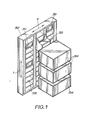
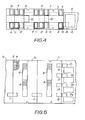
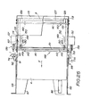
- an automatic tape cassette loading device comprises a plurality of separate cassette storage shelf blocks 1 1 , 1 2 , 1 3 ,... placed side-by-side or in tandem, and a VTR housing block 3 for containing a number of, herein four, VTRs 2 1' 2 2 ,2 3 ,2 4 , capable of operating in at least a reproducing mode and arranged vertically one upon another.
- Each of the cassette storage shelf blocks 1 1 , 1 2 , 1 3 ,... includes a first cassette storage shelf portion 6 and a second cassette storage shelf portion 7 arranged in facing relation to each other on a foundation or base with a predetermined gap or aisle therebetween.
- Each of the shelf portions 6 and 7 includes a matrix of horizontal rows and vertical columns of cassette storage compartments 5 for storing the tape cassettes 4.
- an upper vertically elongate cassette reception opening 8 through which the tape cassettes 4 can be manually inserted into compartments 5 aligned therewith, and a lower vertically elongate cassette take-out opening 9 whereby the tape cassettes 4 earlier stored within the cassette storage shelf portions 6, 7 and now being out of use can be removed from compartments aligned with the opening 9.
- the cassette storage shelf blocks 1 1 , 1 2 , 1 3 ,... are each provided with a cassette transfer device 10 which is arranged in the gap or aisle between the respective first and second cassette storage shelf portions 6 and 7.
- Each transfer device 10 can introduce and take out tape cassettes into and from the cassette storage compartments 5 of the cassette storage shelf portions 6, 7 and also transfer the thus introduced or taken out tape cassettes 4 vertically or transversely within the respective one of the cassette storage shelf blocks 1 1 , 1 2 , 1 3 .
- a cassette delivery unit 11 constructed as later described and to effect delivery of tape cassettes transferred by a cassette transfer device 10 within one of the storage shelf blocks 1 1 , 1 2 , 1 3 ,... to an adjacent one of the storage shelf blocks 1 1 , 1 2 , 1 3 ,....
- Each such cassette delivery unit 11 is mounted in a storage section 12 formed by cutting away parts of cassette sotrage compartments 5 of mutually adjoining first storage shelf portions 6 of storage shelf blocks 1 1 , 1 2 , 1 3 .
- the VTR housing block 3 is placed next to the first cassette storage shelf block 1,, that is, at the right-hand end of the series of cassette storage shelf blocks 1 1 , 1 2 , 1 3 shown arranged side-by-side in Figure 4.
- This VTR housing block 33 is also constructed as a block separate from the cassette storage shelf blocks 1 1 , 1 2 , 1 3 ,....
- the VTR housing block 3 and the first cassette storage shelf block 1 1 adjacent thereto are also provided with cassette delivery units 13 similar to the delivery units 11 described above and each suited to deliver a tape cassette 4 transferred thereto by the cassette transfer device 10 associated with the cassette storage shelf block 1 1 towards the respective VTR 2 1 , 2 2 , 2 3' 2 4 ...
- the cassette delivery units 13 are each mounted in a storage section 14 formed in parts of the cassette storage compartments 5 of the first shelf portion 6 of the shelf block 1 1 and in parts of the VTR housing block 3 adjacent to the respective VTR. These cassette delivery units 13 are operatively associated with automatic cassette loading and discharging devices situated within the VTR housing block 3, as later described, and can automatically charge or discharge the tape cassettes 4 between the cassette delivery units 13 and the respective VTRs 2 1 , 2 2 , 2 3 , 2 4 ,....
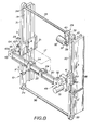
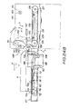
- each cassette transfer device 10 included in the automatic tape cassette loading device will now be explained with reference to Figures 6-12.
- the cassette transfer device 10 is shown to include a cassette transfer member or housing 17 provided with a lower cassette transfer passage 15 and an upper cassette transfer passage 16, and a driving device for effecting vertical and transverse movements of the cassette transfer member 17.
- the basic operation of the transfer device 10 is as follows: For transferring a tape cassette 4 from a selected cassette sotrage compartment 5, for example, in the shelf portion 7, to a selected compartment 5 in the shelf portion 6, the tape cassette 4 from such compartment 5 in the shelf portion 7 is introduced in the direction of arrow a ( Figure 6) into the lower cassette transfer passage 15 of the cassette transfer member 17.
- the member 17 is then transferred laterally and vertically to align its passage 15 with the selected compartment 5 in the shelf portion 6, and the tape cassette 4 is introduced into the selected compartment 5 out of the transfer passage 15 in the direction of arrow c ( Figure 6).
- the tape cassette 4 is introduced in the direction of arrow c' ( Figure 7) into the upper cassette transfer passage 16 of the transfer member 17 from the compartment in the shelf portion 6.
- the transfer member 17 is then transferred laterally and vertically to the original cassette storage compartment 5 of the shelf portion 7 and the tape cassette 4 is then transferred in the direction of arrow a' ( Figure 7) out of cassette transfer passage 16 so as to be stored in the original cassette storage compartment 5 in the shelf portion 7.
- the cassette transfer device 10 is similarly employed for transferring a cassette 4 between a compartment 5 of a storage shelf portion 6 or 7 and a delivery unit 11 or 13.
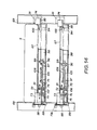
- the driving device includes a pair of transversely spaced apart vertical guide rails 18 and 19 on which a pair of vertically slidable slide units 20 and 21, respectively, are mounted.
- a horizontal guide rail 22 extends between the vertical guide rails 18 and 19 and has one end fixedly connected to the slide unit 20 while its other end is connected to the slide unit 21 by a universal joint 23 which is hereinafter described in detail.
- the cassette transfer member 17 is mounted on top of a pair of sliding elements 24 which are slidable transversely on the horizontal guide rail 22.
- the guide rails 18 and 19 and the sliding units 20 and 21 are constructed as substantially identical mirror images of each other.
- upper and lower paired guide rolls 26 are mounted for rotation at the forward and rear ends of the sliding unit 20 and are engaged within vertically extending guide grooves 25 formed in the front and rear end faces of the vertically extending guide rail 18.
- Front and rear lateral faces of a vertically extending guide rib 27 directed laterally inward along the inner surface of the vertically extending guide rail 18 are sandwiched between upper and lower paired guide rolls 28 rotatably mounted on the sliding unit 20.
- the sliding units 20 and 21 are smoothly slidable along the guide grooves 25 and the vertical guide ribs 27 of the rails 18 and 19.
- the sliding units 20 and 21 are moved vertically in synchronism with each other along the vertically extending guide rails 18 and 19 by a vertical driving unit 29 which, as shown in Figure 8, includes left and right paired timing belts 30 and 31 extending vertically adjacent the guide rails 18 and 19 respectively, and a driving motor 32 for driving the timing belts.
- the timing belts 30 and 31 extend between upper and lower paired pulleys 33 and 34, respectively, which are secured on upper and lower shafts 35 and 36 rotatably mounted at the upper and lower ends of the guide rails 18 and 19.
- a further timing belt 40 runs about pulleys 38 and 39 which respectively are secured to the upper rotary shaft 35 and to an output shaft 37 of the driving motor 32.
- the timing belts 30 and 31 are secured to the front end faces of the sliding units 20 and 21, respectively, by rail holders 41 and 42.
- the timing belts 30 and 31 are driven simultaneously in the vertical directions as indicated by arrows b, b' in Figure 8 so that the guide rail 22 is made to undergo a vertical translatory movement through the sliding elements 20 and 21 to cause corresponding vertical movement of the cassette transfer member 17.
- the front and rear longitudinal faces of the horizontally extending guide rail 22 are formed with paired horizontally extending guide grooves 44 in which are engaged forward and rear paired guide rolls 45 rotatably mounted at the forward and rear ends of the sliding elements 24, as shown in Figures 11 and 12.
- the front and rear lateral faces of a guide rib 46 directed upwardly and extending along the horizontally extending guide rail 22 are sandwiched between forward and rear paired guide rolls 47 rotatably mounted on the sliding elements 24 ( Figure 12).
- the sliding elements 24 are guided by the rib 46 and the rolls 47 so as to be slidable smoothly along the horizontally extending guide rail 22.
- the sliding elements 24 are moved transversely along the horizontally extending guide rail 22 by a horizontal driving unit 49 which, as shown in Figure 11, includes a timing belt 50 extending horizontally along the guide rail 22 and a driving electric motor 51.
- the timing belt 50 extends around left and right paired pulleys 54 and 55 rotatably disposed in pulley housings 52 and 53 secured to the opposite ends, respectively, of the horizontally extending guide rail 22.
- the driving motor 51 is mounted on a belt housing 56 secured to the pulley housing 52.
- the timing belt 50 is secured by belt retainers 62 to the upper surfaces of the sliding elements 24.
- a timing belt 61 runs around a pair of pulleys 59 and 60 respectively secured to a motor shaft 57 of the driving electric motor 51 and to a rotary shaft 58 connected with the pulley 54.
- the timing belt 50 is driven through the timing belt 61 and the shaft 58 to move in the transverse directions indicated by the arrows d and d * in Figure 11 without slipping so that the cassette transfer member 17 is similarly moved transversely along the guide rail 22 by the sliding elements 24.
- the motor shaft 37 of the driving motor 32, the rotary shaft 35, the motor shaft 57 of the driving motor 51 and the rotary shaft 58 are provided with respective position encoding devices for effecting address allocation, in the vertical and transverse, directions of the cassette transfer member 17 with respect to the cassette storage compartments 5 of the cassette storage portions 6 and 7 and with respect to the cassette delivery units 11 and 13.
- a universal joint 23 is provided between the sliding unit 21 and the adjacent end of the guide rail 22 and is constituted by a rail holder 64 secured to the pulley housing 53 and the roll holder 42 on the sliding unit 21 ( Figure 11).
- three rolls 65 are mounted for rotation on the roll holder 42 and engage in three respective grooves 65a provided in the rail holder 64.
- any change in the distance between the sliding units 20 and 21, caused by deviation from exact parallelism of the guide rails 18 and 19, experienced during the movement of the horizontally extending guide rail 22 along the guide rails 18 and 19 in the vertical direction may be accommodated by the freedom of movement in the transverse and rotational directions afforded by the universal joint 23.
- any distortion of the sliding units 20 and 21 relative to the guide rails 18 and 19, caused by deviations from parallelism, with resultant binding or large sliding resistance may be prevented so that the sliding units 20 and 21 can slide smoothly and noiselessly along the vertically extending guide rails 18 and 19.
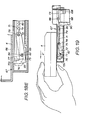
- Each cassette storage compartment 5 of the first and second cassette storage shelf portions 6 and 7 is provided with a cassette push-out unit 66 which will be described with reference to Figures 13-17.
- Each cassette storage compartment 5 is in the form of a parallelepipedic space defined by horizontally extending vertically spaced shelf plates 67 and vertically extending left and right side plates 68 and 69.
- Each cassette storage compartment 5 has an opening 70 for insertion and removal of a tape cassette and which faces toward the aisle or gap between the shelf portions 6 and 7, that is, towards the cassette transfer member 17.
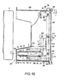
- the cassette push-out unit 66 comprises a push-out member 72 biased by a pair of springs 71 in the direction of the arrow a in Figure 13 from a retracted or inoperative position within the respective compartment 5 towards an extended or operative position in the vicinity of the cassette insertion and removal opening 70, a stopper 73 provided adjacent the cassette insertion and removal opening 70, and a detection member 74 also adjacent the opening 70 of the cassette storage compartment 5 ( Figure 14).
- a pair of slide guide plates 75 are secured parallel to each other along the left and right sides of the trajectory of the reciprocating movement of the push-out member 72, as shown in Figures 14-17.
- the push-out member 72 is slidably mounted within a slide plate 76 of channel-shaped cross-section which is slidably disposed between the slide guide plates 75.
- the push-out member 72 is L-shaped and elongate in its reciprocating direction so as to define an up-turned hook 72a at its end directed into the respective compartment 5.
- the push-out member 72 has a pair of slide pins 77 and 78 extending horizontally from its opposite sides at the opposite end portions of the member 72.
- a guide pin 81 is installed ahead of the push-out member 72 between the forward end parts of the slide guide plates 75 and is slidably engaged in both the guide slots 79 of the slide plate 76.
- the push-out member 72 is biased forwardly or in the direction of arrow a in Figure 15 by the paired springs 71 which, at one end, are connected to the ends of the guide pin 78.
- the other or forward ends of the springs 71 are suitably anchored to a forward portion of the shelf 67.
- the guide slots 80 of the slide guide plates 75 are formed with lock portions 82 extending downwards at right angles at the ends of the guide grooves 80 remote from the opening 70.
- the corresponding end parts of the guide slots 79 of the slide plate 76 are similarly formed with downwardly directed locking portions 83.
- Each locking portion 83 has an undercut defined by a small projection 84, and the lower edge 85 of each locking portion 83 is inclined or extends obliquely upward towards the interior of the respective cassette storage compartment 5.
- the hook 72a of the push-out member 72 can project through an elongate opening 86 ( Figure 13) in the shelf plate 67 so as to project thereabove.
- the stopper 73 is substantially L-shaped, as shown in Figures 13-16, and is pivotally mounted on the side plate 68 for turning about a pin 88, as indicated by arrows h, h' in Figure 13. It will be noted that the stopper 73 can turn in a vertical plane within a slit 89 formed in a flange 87 extending aiong the edge of the side plate 68 bordering the opening 70.
- the stopper 73 is biased by a spring 90 so as to be turned in the direction of arrow h in Figure 13.
- the detection member 74 is disposed within a cut-out 91 ( Figure 14) formed in the other side plate 69 adjacent the opening 70, and the member 74 is formed with front and rear inclined edges 92 and 93 ( Figure 15).
- the detection member 74 is mounted at one end of an L-shaped link 95 which is pivotally mounted at its other end on a pin 94 carried by the shelf plate 67 so that the detection member 74 may be pivoted in the transverse direction, as indicated by arrows i, it in Figure 15.
- the opposite ends of a link 98 are respectively connected by pins 99 and 100 to the L-shaped link 95 and to one end of a pivotally mounted L-shaped lever 97.
- the other end of the L-shaped lever 97 is connected to the slide plate 76 by a pin 101 engaging in a laterally elongate opening 102 in the slide plate 76.
- the L-shaped lever 97 is urged by a spring 103 in the direction indicated by arrow 1 in Figure 15 so that the slide plate 76 is thereby biased in the direction indicated by arrow a' and the detection member 74 is also biased into the cassette storage section 5, that is, in the direction indicated by arrow i' in Figure 15.
- a stopper locking plate 105 has an elongate opening 104 at one end receiving the pin 99 of the L-shaped lever 97, and further has an elongate opening 107 receiving a guide pin 106 provided on the shelf plate 67.
- the end part of the stopper locking plate 105 remote from the pin 99 may project above the stopper 73 through a cut-out 108 provided in the side plate 68.
- the stopper locking plate 105 is biased by a spring 109 in the direction indicated by arrow k in Figure 15.
- a new tape cassette is inserted initially into one of the cassette storage compartments 5 communicating with the cassette reception opening 8 formed by partially cutting away the front side of the respective cassette storage compartments 5 provided in the first cassette storage shelf portion 6.
- the tape cassette 4 manually inserted into a cassette storage compartment 5 communicating with the cassette reception opening 8 may then be transferred to, and stored in a predetermined one of the cassette storage compartments 5 of the first and second cassette storage shelf portions 6, 7 by the operation of the respective cassette transfer device 10.
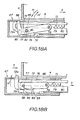
- the push-out member 72 of the respective cassette push-out unit 66 is locked in the retracted position shown in Figure 18A to which it has been shifted against the force of the springs 71.
- the push-out member 72 has been rocked in the direction of arrow m, about the slide pin 78, and the other slide pin 77 is held under the small projection 84 and within the locking portions 82 and 83 of the guide slots 79 and 80.
- the hook 72a of the push-out member 72 is disposed below the lower surface of the compartment 5, as shown in Figure 18A.
- the stopper 73 biased by the spring 90 in the direction of arrow h in Figure 13 protrudes into the cassette insertion and removal opening 70, as shown in Figure 14.
- the detection member 74 biased by the spring 103 in the direction of arrow i' in Figure 15 intrudes into the cassette storage compartment 5.
- the leading end of the stopper locking plate 105 biased by the spring 109 in the direction of arrow k in Figure 15 abuts against the lateral side of the stopper 73.
- the L-shaped lever 97 can be turned by the spring 103 in the direction of arrow 1 without limitation by the stopper locking plate 105 so that the detection member 74 intrudes into the cassette storage compartment 5 as shown in Figure 15.
- the tape cassette 4 is introduced horizontally into the compartment 5 through the cassette reception opening 8 in the direction of arrow a without any interference from the hook 72a of the push-out member 72.
- the push-out member 72 is urged by the springs 71 from the retracted position of Figure 15 towards the opening 70, with the hook 72a of the push-out member 72 engaging and thrusting the tape cassette 4 in the direction of the arrow a, as shown in Figure 18C.
- the tape cassette 4 is automatically moved by the push-out member 72 in the direction of arrow a until it comes to a standstill with a corner of the leading part of the cassette in abutment with the stopper 73, as shown in Figure 16.
- the tape cassette 4 then continues to be maintained in this state.
- the push-out member 72 is thus moved in the direction of arrow a, the slide pins 77, 78 are moved within the guide slots 79, 80 so that the push-out member 72 is moved horizontally.
- the detection member 74 is free to be moved by the force of the spring 103 in the direction of arrow it through the L-shaped lever 97, the link member 98 and the L-shaped link member 95.
- the slide plate 76 is also displaced by the force of the spring 103 in the direction of arrow a'.
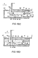
- the push-out member 72 After having been thrust to its retracted position in the direction of arrow a' in Figure 18D, the push-out member 72 is turned in the direction of the arrow m about the slide pin 78 and then locked with the slide pin 77 moved out of the guide slots 79 and 80 into the locking portions 82 and 83 and being held therein by the projection 84.
- the hook 72a of the push-out member 72 is depressed through the elongate opening 86 into the interior of the shelf plate 67 so as to be disposed below the bottom surface or floor of the cassette sotrage compartment 5, as shown in Figure 18E.
- the manual withdrawal of the cassette 4 from the compartment 5 is completed, as shown in Figure 19.
- the cassette transfer member 17 is in the form of a housing having left and right side plates 113 and 114, a ceiling plate 115 and a bottom plate 116.
- the opposite ends of the upper and lower cassette transfer passage 15 and 16 are open.
- the actuating mechanism 110 is attached to the outer surface of the side plate 113 at the lower portion thereof.
- the actuating mechamism 110 at the side of transfer member 17 facing the second cassette storage shelf portion 7 is shown, but it is to be understood that a similar actuating mechanism 110 is provided at the side of the transfer member 17 facing the first cassette storage shelf 6 and is omitted only for the sake of clarity.
- the illustrated actuating mechanism 110 includes an actuating lever 117 for displacing the stopper 73 to an inoperative position and a driving solenoid 118.
- the actuating lever 117 is L-shaped and pivotally mounted on the side plate 113 by means of a pin 119 situated between arms 117a and 117b of the lever 117.
- the arm 117a is engageable from above with the stopper 73, and the other arm 117b is connected through a link 120 to an armature 121 of the solenoid 118 by means of a connecting pin 122
- the actuating lever 117 is biased to turn in the direction of arrow n to the position shown in broken lines in Figure 21 by a spring 123 connected to the pin 122 for extending the armature 121 of the solenoid 118.
- the solenoid 118 is energized to retract its armature 121, the actuating lever 117 is turned thereby in the direction of arrow n' to the position shown in full lines in Figure 21.
- the cassette feed mechanisms 111 and 112 are identical, and are shown to include, below the front and rear portions of the cassette transfer passages 15 and 16, driving shafts 124 and 125 and driven shafts 126 and 127, respectively, which are horizontally journalled between the side plates 113 and 114 in parallel with each other (Figure 22).
- Feed rolls 128 and 129 are respectively secured on the left and right hand end portions of the shafts 124 and 126 and the shafts 125 and 127 ( Figure 20).
- Pulleys 130 and 131 are secured to the left and right end portions of shafts 124 and 126 and of shafts 125 and 127, and timing belts 132 and 133 extend around and between pulleys 130, 131, respectively.
- the upper horizontal runs of the timing belts 132 and 133 are guided horizontally on left and right guides 134 and 135, respectively, secured horizontally to the inner surfaces of the side plates 113 and 114.
- the driving shafts 124 and 125 are rotatably driven through speed reducing untis 138 and 139 by electric motors 136 and 137 mounted on the outer surface of the side plate 114 ( Figure 22).
- Idler shafts 140 and 141 are horizontally arranged between the side plates 113 and 114, in parallel with each other, above the front and rear portions of the cassette transfer apssages 15 and 16, respectively.
- Idler rollers 142 and 143 are rotatably mounted on the opposite end portion of the shafts 140 and 141, respectively, which are movably supported in vertically elongate slots 144 and 145 in the side plates 113 and 114, and biased downwardly by paired springs 146 and 147.
- Left and right paired rotary arms 149 are secured, at one end, on end portions of a horizontal rotary shaft 151 which extends between, and has its opposite ends journalled in the side plates 113 and 114.
- the rotary shaft 151 is arranged above a delivery opening 148 at the end of the upper cassette transfer passage 116 facing towards the storage shelf portion 7.
- Rolls 150 are rotatably mounted on the free end portions of the arms 149 which are angularly displaced, together with the shaft 151, in one or the other of the directions indicated by arrows s and s' in Figure 24B by a reversible electric motor 152 mounted on the outer surface of the side plate 113 and connected with the shaft 151 through a speed reduction unit 153 ( Figure 24A).
- the solenoid 118 is energized to retract its armature 121 in the direction of arrow o against the force of the spring 123 so that the actuating lever 117 is turned in the direction of the arrow n' from the position shown in broken lines to the position shown in solid lines.
- the push-out unit 66 thereby delivers the cassette 4 into the cassette transfer passage 15 and continues to propel the cassette until the slide pin 78, on which the push-out member 72 is mounted, abuts against the end of the guide slot 80 near to the opening 70. At such time, the bottom surface of the tape cassette 4 is transferred onto the upper runs of the belts 132 and the feed rolls 130 on the driving shaft 124 which is already being rotatably driven by operation of the motor 136 in the direction for moving the upper runs of the belts 132 in the direction of the arrows g in Figures 21 and 22.
- the tape cassette 4 is automatically conveyed further into the cassette transfer passage 15 to a position shown in broken lines in Figures 21 and 23.
- the idler rollers 142 are urged downwardly against the upper surface of the tape cassette by the springs 146 so as to avoid slippage between the cassette being transferred and the feed rolls 130 and the timing belts 132.
- the detection member 74 is free to be returned by the force of the spring 103 in the direction of the arrow i' from the position of Figure 16 to the position shown on Figure 15.
- the stopper locking plate 105 is driven by the spring 109 in the direction of arrow k in Figure 15 so that the leading end portion of the stopper locking plate 105 projects above the stopper 73 which is then being held in its lowered or inoperative position by the actuating lever 117.
- the stopper 73 is thereafter held or locked in its lowered or inoperative position by the leading end portion of the stopper locking plate 105.
- the cassette transfer device 10 automatically to return a tape cassette 4 from the cassette transfer passage 16 to a cassette storage compartment 5 from which is had been previously removed in the manner described above, will now be explained with refernece to Figures 24A, 24B and 25.
- the cassette transfer member 17 is positioned so that its cassette transfer passage 16 is aligned with the opening 70 of the cassette storage compartment 5 into which the tape cassette is to be returned, as shown in Figure 24A.
- the driving motor 137 is energized to rotate the driving shaft 125 in the direction for effecting movement of the timing belts 133 in the direction of arrow r.
- the combined action of the rotated feed rolls 131 on the shaft 125 and the belts 133 serves to drive the tape cassette 4 thereon through the passage 16 in the direction of the arrow r.
- the tape cassette 4 is pushed-out, rear end first, through the exit opening 148, as indicated in solid lines in Figure 24A and is propelled into the aligned compartment 5 through the opening 70 thereof.
- the idler rolls 143 are pressed downardly on the upper surface of the tape cassette by the springs 147 so as to avoid slippage of the drive rolls 131 and the belts 133 relative to the bottom surface of the cassette 4.
- a sensor 157 figure 22) attached to the side plate 114 detects the trailing end of the tape cassette 4 being moved in the direction of arrow r and, in response thereto, the motor 152 is energized in the forward direction, that is, in the direction for turning the shaft 151 and the arms 149 thereon in the direction of arrow s in Figure 24B.
- the rolls 150 at the free ends of the arms 149 are brought against the trailing end of the tape cassette 4 to continue the movement of the tape cassette 4 in the direction of arrow a' off the belts 133 and to the fully inserted position of the cassette 4, as shown in full lines on Figure 24B.
- the cassette thrusts against the hook 72a of the push-out member 72 so that the hook is displaced by the cassette in the direction of arrow a' against the force of the springs 71.
- a sensor 158 ( Figures 248 and 24A) is attached to the cassette transfer member 17 and senses when the arms 149 have returned the tape cassette 4 to its fully inserted position in the compartment 5 so that the stopper 73 is free to return to its raised or operative position to block movement of the cassette out of the opening 70.
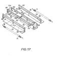
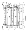
- the cassette delivery units 11 and 13 respectively provided between the adjacent cassette storage shelf blocks 1 1 and 1 2 and 1 2 and 1 3 , and between the VTR housing block 3 and the cassette storage shelf portion 6 of the adjacent cassette storage shelf block 1 1 , are of identical construction, so that only the cassette delivery unit 11 will be described in detail herein with reference to Figures 26-30.
- Each cassette delivery unit 11 includes a rectangular frame 160 dimensioned to be housed in the housing section 12 in place of the cassette storage compartments 5 at the adjoining portions of the cassette storage shelf portions 6 of the blocks 1 1 and 12, or of the blocks 1 2 and 1 3'
- a cassette feed table 161 is mounted movably within the frame 160 so as to be capable of delivering a tape cassette 4 between the cassette storage shelf portions 6 of the blocks 1 1 and 1 2 or of the blocks 1 2 and 1 3 .
- the frame member 160 is open at the side thereof facing the cassette transfer device 10 so as to define a cassette insertion and removal opening 162 through which a tape cassette 4 can be readily transferred between the cassette transfer member 17 of the unit 10 and the cassette feed table 161.
- the cassette feed table 161 has a slide block 163 at the bottom thereof which is slidable along a horizontal guide shaft 168 supported, at its ends, by upright end pieces 166 and 167 of a U-shaped supporting frame 165 which is securely mounted, in turn, on a bottom plate 164 of the frame member 160.
- the cassette feed table 161 is movable between a first position shown in solid lines in Figure 26, and which may be adjacent the cassette storage shelf portion 6 of the block 1 1 or 1 2 , in the case of the delivery unit 11 between the shelf blocks 1 1 and 1 2 , and a second position shown in broken lines in Figure 26, and which is adjacent the cassette storage shelf portion 6 of the other block 1 2 or 1 1 , respectively.
- the cassette feed table 161 is moved between the above noted first and second positions to deliver a tape cassette 4 thereon from one to the other of the adjoining cassette storage shelf blocks 1 1 and 1 2 , and the delivery unit 11 is further operative at each of the described first and second positions of its table 161 to effect transfer of a tape cassette between the table 161 and the cassette transfer device 10 associated with the block 1 1 or 1 2 , respectively.
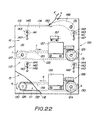
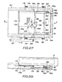
- the structure of the cassette feed table 161 for performing the above functions is shown to include a pair of cassette guides 172 and 173 attached to opposite sides of the table 161 to receive and guide a tape cassette 4 therebetween. Between the guides 172 and 173 there is provided a first cassette receiving plate 174 onto which a tape cassette 4 is introduced in the direction of the arrow P ( Figure 27) from the cassette transfer device 10.
- the first cassette receiving plate 174 has a rim or flange 175 acting as a stopper engageable by the leading end of a cassette inserted in the direction of the arrow P and acting to limit the insertion movement of the cassette relative to the plate 174.
- Slide guide shafts 176 and 177 which are axially aligned with each other project from opposite sides of the cassette receiving plate 174 and are slidably received in elongate guide slots 178a and 179a extending through and along base portions of cassette guides 172 and 173, respectively. Further, guide pins 178 and 179 project in opposite directions from the plate 174 and are slidably received in the elongate guide slots 178a and 179a, respectively.
- the cassette receiving plate 174 is mounted for sliding movement relative to the table 161, for example, between the positions shown on Figures 27 and 29, respectively.
- a second cassette receiving plate 180 is provided on the table 161 between the table 174 and the cassette insertion and removal opening 162, that is, at the portion of the table 161 facing towards the cassette transfer device 10.
- an upstanding rim or flange 181 for engaging an end of a tape cassette 4 inserted on the table 161 in the direction of the arrow P on Figure 30 so as to inhibit its removal from the table 161 in the opposite direction, that is, in the direction of the arrow Q.
- the second cassette receiving plate 180 is mounted to rock on a supporting shaft 182 which extends along the edge of the plate 180 remote from the rim 181, and which has its end portions journalled in base portions of the cassette guides 172 and 173.
- Rocking of the cassette receiving plate 180 is controlled by cam-follower rolls 183 and 184 rotatably mounted at opposite ends of the plate 180 between the rim 181 and the supporting shaft 182, and being engageable, from above, with a slidable cam plate 185.
- the cam plate 185 is mounted for reciprocal limited movement relative to the table 161 in the direction of the arrows P and Q, for example, by means of pins 186 and 187 fixed relative to the table 161 and slidably received in slots 188 and 189 formed in the cam plate 185.
- the portion of the cam plate 185 underlying the second cassette receiving plate 180 is formed with inclined cam sections 190 and 191 engageable by cam follower rolls 183 and 184, respectively.
- the second cassette receiving plate 180 is rocked between the positions shown in Figures 28 and 30, respectively.
- Tension springs 192 and 193 are connected, at one end, to the guide shafts 176 and 177, respectively, and the other ends of the springs 192 and 193 are connected to end portions of the shaft 182. Thus, the springs 192 and 193 urge the first cassette receiving plate 174 toward the second cassette receiving plate 180, for example, to the relative positions shown in Figures 27 and 28.
- the cassette feed table 161 is further provided with an operating lever 194 which is mounted for rotation on a shaft 195 supported by the feed table 161 and biased to turn in the clockwise direction, that is, the direction of arrow R in Figure 29, by means of a tension spring 196 connected between the lever 194 and the table 161.
- One end portion of the lever 194 extends beyond the table 161 at the side of the table having the guide 173 thereon and carries a pin 198 to which a horizontally extending link 197 is pivotally connected.
- the link 197 is shown to extend parallel to the cassette guide 173 and can be shifted longitudinally to turn the lever 194 about its supporting shaft 195.
- an actuating roll 200 rotatable on a shaft 201 and abuttable against a projection 199 extending from the inner side of the first cassette receiving plate 174.
- a bent flange 199a is formed along the edge of the projection 199 to provide a bearing surface for engagement by the roll 200 and leads into a guide flange 174a extending along the undersurface of the cassette receiving plate 174.
- the end of the operating lever 194 remote from the pin 198 carries a pin 203 engaging in a laterally elongate slot 202 formed in the cam plate 185.
- the operating lever 194 when a tape cassette 4 is to be inserted on the table 161, the operating lever 194 is in the position shown in Figure 27 so that the actuating roll 200 on the operating lever 194 is disengaged from the projection 199 of the first cassette receiving plate 174 which is thereby moved toward the second cassette receiving plate 180 by the force of the tension springs 192 and 193.
- the pin 203 thereon causes displacement of the cam plate 185 in the direction of arrow P so that the cam follower rolls 183 and 184 are positioned on relatively lower horizontal surfaces 190b and 191b of cam sections 190 and 191, respectively.
- the second cassette receiving plate 180 is rocked or inclined downwardly from its support shaft 182 so that its rim 181 is at a relatively depressed position (Figure 28).
- the second cassette receiving plate 180 is rocked upwardly about the supporting shaft 182 to the horizontal position shown in Figure 30, and at which the rim 181 on the plate 180 engages the adjacent end of the tape cassette 4 to retain the cassette between the stopper rim 175 and the rim 181.
- movements of the cassette feed table 161 between the positions shown in full lines and in broken lines, respectively, are effected by a feed mechanism including toothed pulleys or sprockets 169 and 170 rotatably mounted on the supporting frame 165 adjacent the upright end pieces 166 and 167 thereof, a timing belt 168 running around the sprockets 169 and 170 and having its upper run suitably fixed to the slide block 163, and a drive unit 170a including a conventional reversible electric motor and speed reduction gearing rotatably to drive the sprocket 170.
- the drive unit 170a including a conventional reversible electric motor and speed reduction gearing rotatably to drive the sprocket 170.
- the tape cassette 4 thereon is discharged from the feed table 161 into the cassette transfer device 10 associated with the cassette storage shelf block 11, 1 2 or 1 3 to which the table 161 has been fed. More particularly, in order to discharge the tape cassette 4 from the feed table 161, the horizontally extending link 197 is suitably displaced longitudinally in the direction of arrow x in Figure 29 to effect counterclockwise turning of the operating lever 194 with the result that the roll 200 is disengaged from the projection 199 on the cassette receiving plate 174.
- the springs 192 and 193 can act on the cassette receiving plate 174 to move it in the direction of arrow Q from the position shown in Figure 29 toward the position shown in Figure 27.
- the counterclockwise turning of the operating lever 194 in the direction of arrow R' in Figure 27 also effects movement of the cam plate 185 in the direction of arrow P so that the cam-follower rolls 183 and 184 are engaged by the inclined cam surfaces 190 and 191 and then by the lower horizontal surfaces 190b and 191b, respectively.
- the cassette receiving plate 180 is rocked downwardly about its supporting shaft 182, as shown in Figure 28, to disengage the 181 from the tape cassette 4.
- the springs 192 and 193 can now displace the cassette receiving plate 174 in the direction of arrow Q from the position shown in Figures 29 and 30 to the position shown in Figures 27 and 28 with the result that the stopper rim 175 on the plate 174 propels the tape cassette 4 at least partly off the feed table 161, and at least partly into the cassette transfer passage 15 of the transfer device 10. Thereafter, the transfer device takes over the completion of the insertion of the cassette 4 into the passage 15 in the same manner as described above with respect to the discharge of a cassette from a compartment 5 into the transfer device 10. As the cassette receiving plate 174 is moved by the springs 192 and 193 from the position of Figure 29 to the position of Figure 27, the roll 200 engages the side of the flange 174a to hold the lever 194 against turning by the spring 196.
- Each of the VTRs 21,22,23 and 2 4 contained in the VTR housing block 3 has an automatic cassette input and output device 227 which is in facing relation to a cassette inlet and outlet opening 226 ( Figure 35) of the respective VTR.
- the automatic cassette input and output device 227 associated with the VTR 2 1 will be described herein with reference to Figures 31-35, and it will be understood that the other VTRs have identical automatic input and output devices associated therewith.
- the purpose of the device 227 is to effect input into the opening 226 of the VTR 2 1 of the tape cassette 4 which is discharged from the cassette delivery unit 13, or to effect the output from the opening 226 of a cassette 4 ejected from the VTR 2 1 , and the introduction of such an ejected cassette into the cassette delivery unit 13.
- the automatic cassette input and output device 227 has a substantially rectangular frame 228 attached to the front surface of the housing of the VTR 2 1 about the opening 226, as shown in Figures 31 and 35.
- Within the frame 228 there are disposed an upper shaft 229 and a lower shaft 230 extending horizontally and parallel to each other above and below, respectively, the path of cassettes into and out of the opening 226.
- the upper shaft 229 has its opposite end portions extending through and being rotatably supported by bearings 233 secured to upper parts of opposed side members 231 and 232 of the frame 228.
- the upper shaft 229 is mounted for rotation about a fixed axis.
- the lower shaft 230 is mounted for rotation about an axis which is capable of limited displacements in the vertical direction.
- bell-cranks 234 and 235 are situated outside the side members 231 and 232, respectively, and are pivotally mounted on pins 236 supported by lower parts of the adjacent side members 231 and 232 of the frame 228.
- the bell-cranks 234 and 235 have approximately horizontally extending arms carrying bearings 237 in which the adjacent ends of the lower shaft 230 are rotatably mounted.
- the other, or approximately vertically extending arms of the bell-cranks 234 and 235 are connected to springs 238, by which the bell-cranks 234 and 235 are urged to pivot about their respective pins 236 in the direction of arrow t in Figures 33 and 35.
- Idler rollers 240 are mounted on opposite end portions of the upper shaft 229 within the frame 228 so as to be freely rotatable with respect to the shaft 229. Also mounted on the opposite end portions of the shaft 229 between the side frame members 231 and 232, are arms 242 which, however, are secured to the shaft 229 for turning with the shaft 229. The free ends of the rotary arms 242 have rollers 241 rotatably mounted thereon.
- Feed rolls 243 are secured on the opposite end portions of the lower shaft 230 within the frame 228.
- a reversible electric motor 245 is mounted on the side frame member 231 by way of a bracket 244 and is suitably coupled with the adjacent end of the shaft 229 for driving the shaft 229.
- Another reversible electric motor 246 is mounted on the substantially horizontal portion of the bell-crank 234 which, as shown on Figure 31, is desirably of U-shaped cross-section. The motor 246 is suitably coupled with the adjacent end of the shaft 230 for rotating the shaft 230.
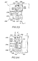
- Automatic roll-lifting devices 248 are provided at the side frame members 231 and 232 for controlling the vertical position of the shaft 230, and hence of the feed rolls 243 thereon.
- Each of the roll-lifting devices 248 includes a rotary cam 249 secured to the adjacent end of the upper shaft 229, and a cam-following slide plate 250 which is mounted for vertical movement on the adjacent side frame member 231 or 232 between the respective cam member 249 and the bell-crank 234 and 235.
- Each of the cams 249 is shown in Figures 32-34 to be in the form of a substantially circular disc having a recess or cut-out 251 in its otherwise circular periphery 239a.
- Each slide plate 250 has elongate slots 253 therein slidably receiving mounting pins 252 extending from the adjacent side frame member 231 or 232 to permit vertical movement of the slide plates 250.
- Each of the slide plates 250 has a rounded upper end bearing against the peripheral surface of the respective cam 249, while the lower end of each of the slide plates 250 is engaged from below by the substantially horizontal arm portion of the respective bell-crank 234 or 235.
- the springs 238, in urging the bell-cranks 234 and 235 to pivot in the direction of arrow t in Figure 33 also urge the slide plates 250 vertically upwardly in the direction of arrow u for engagement, at their upper ends, with the peripheries 249a of the cams 249.
- a sensor attachment plate 257 ( Figures 31 and 32) extends from the front of the housing of the VTR 2 1 parallel to the side frame member 232 in the vicinity of the rotary disc 256 and carries three spaced apart sensors 258, 259 and 260 for sensing three respective rotational positions of the projection 255.
- the projection 255 on the disc 256 is rotated in phase with the rotary arms 242 so that the rotational position of the rotary arms 242 can be detected by the sensors 258-260 with reference to the rotational position of the projection 255.
- Another sensor 262 ( Figures 31 and 35) depends from the central portion of the top frame member 261 of the frame 228 and can detect positions of a tape cassette passing through the opening 226 of the VTR 2 1 , as hereinafter described in detail.
- the operation of the device 227 in automatically inserting into the opening 226 of the VTR 2 1 a tape cassette 4 delivered thereto by the respective cassette delivery unit 13 is as follows.
- the link 197 of the unit 13 is suitably displaced in the direction of arrow x in Figure 27 so as to cause the previously described discharge of the tape cassette from the table 161 in the direction toward the opening 226, that is, into the frame 228.
- the motor 246 is suitably energized to drive the shaft 230 on which the rolls 243 are secured.
- the rotary cams 249 on the shaft 229 are rotationally positioned so that the peripheral recesses 251 thereof receive the upper ends of the slide plates 250, as shown in Figures 32 and 33.
- the feed rolls 243 are urged by the springs 238 to their raised position P 4 at which the surfaces of the feed rolls 243, at the top thereof, extend a distance H 1 above the bottom surface of the tape cassette 4 as driven into the device 227 from the delivery unit 13.
- the vertical distance 1 2 measured between the bottom surfaces of the idler rolls 240 on the shaft 229 and the top surfaces of the feed rolls 243 when in the position P 41 is less than the vertical dimension 1 3 of the tape cassette 4 ( Figure 31).
- the sensor 262 detects the trailing end of the tape cassette and, in response thereto, operation of the motor 246 is halted and operation of the motor 245 is commenced so as to turn the shaft 229 and the arms 242, the rotary cams 249 and the rotary disc 256 in the direction of arrow w in Figures 34 and 35.
- the cams 249 are turned from the position shown in Figure 33, the peripheral recesses 251 therein move away from the upper ends of the slide plates 250 with the result that the slide plates 250 are displaced downwardly in the direction of arrow u' in
- the tape cassette 4 within the VTR 2 1 is conventionally ejected automatically out of the opening 226.
- the rotary arms 242 are in the position shown in broken lines in Figure 35 so that the ejected tape cassette 4 comes to rest at a predetermined position in which it abuts against the rolls 241 on the arms 242. Since the upper surfaces of the feed rolls 243 are, at this time, in the lowered position P 51 that is, the distance H 2 below the position P 3 of the bottom surface of the tape cassette 4 being ejected, the feed rolls 243 do not interfere with the ejection of the tape cassette 4.
- the motor 245 When the leading end (considering the direction in which the tape cassette is ejected) of the ejected tape cassette 4 is detected by the sensor 262, the motor 245 is operated in the direction to cause turning of the shaft 229, and hence of the arms 242, the cams 249 and the disc 256 thereon, in the direction of arrow w i in Figure 34.
- the arms 242 are returned to the inoperative position shown in full lines in Figures 32 and 35, the projection 255 on the disc 256 is returned to its original position ( Figure 33) where it is detected by the sensor 258 and, in response thereto, the operation of the motor 245 is halted.
- the driving motor 246 is operated in the direction for driving the shaft 230 and the feed rolls 243 thereon in the counterclockwise direction, that is, the direction opposed to arrow v in Figure 35.
- the ejected tape cassette 4 is fed out of the opening 226 of the VTR 2 1 and is automatically introduced onto the cassette feed table 161 in the manner previously described.
- selected tape cassettes 4 to be reproduced by the VTRs 2 1 , 2 2 , 2 3 ,--- are removed from the respective storage compartments 5 in the shelf portions 6 and/or 7 of the storage shelf blocks 1 1 , 1 2 , 1 3 ,---, and carried by the cassette transfer devices 10 travelling between the shelf portions 6 and 7 of the respective shelf blocks 1 1 , 1 2 , 1 3 ,---.
- Each cassette transfer device 10 carries the tape cassette 4 deposited therein over the extent of the respective storage block 1 1 , 1 2 , 3 ,---, in the direction toward the VTR housing block 3 and introduces the carried tape cassette 4 onto the cassette feed table 161 of the cassette delivery unit 11 or 13 associated with the respective storage block.
- Such delivery unit 11 or 13 effects delivery of the tape cassette between adjacent ones of the cassette storage shelf blocks 1 1 and 1 2 or 1 2 and 1 3 , or between the cassette storage shelf block 1 1 and the VTR housing block 3, respectively.
- Each cassette thus introduced by the cassette transfer device 10 onto the cassette feed table 161 of one of the cassette delivery units 11 is shifted from one cassette storage shelf block to the next cassette storage shelf block in the direction toward the VTR housing block 3, for example, from the block 1 2 to the block 1,, whereupon the tape cassette is discharged from the cassette feed table 161 into the cassette transfer member 17 of the cassette transfer device 10 associated with cassette storage block 1 1 .
- a tape cassette thus delivered by one of the delivery units 11 from the transfer device 10 associated with storage block 1 2 to the transfer device 10 associated with storage block 1 1 is then carried by the last mentioned transfer device 10 and introduced therefrom onto the cassette feed table 161 of the cassette delivery unit 13 associated with the VTR 2 1 , 2 2 , Z 3 or 2 4 in which the selected tape cassette 4 is to be reproduced. Finally, that selected tape cassette 4 is discharged from the feed table 161 of the cassette delivery unit 13 and loaded into the corresponding VTR through the respective opening 226 by the respective automatic cassette input and output device 227.
- a selected tape cassette 4 stored in a compartment 5 of the cassette storage shelf block 1 3 would be removed from such compartment into the cassette transfer member 17 of the transfer device 10 associated with block 13 and transferred, by such device 10, to the table 161 of the cassette delivery unit 11 bridging the blocks 1 3 and 1 2 .
- the table 161 of that delivery unit 11 would, after shifting, deliver the tape cassette thereon to the cassette transfer device 10 associated with the block 1 2 , and such transfer device 10 would carry the tape cassette for introduction to the table 161 of the delivery unit 11 bridging the cassette storage shelf blocks 1 2 and 1 1 .
- the tape cassette would be delivered to the cassette transfer device 10 associated wtih cassette storage shelf block 1 1 for transfer, by such device 10 to the delivery unit 13 bridging the cassette storage shelf block 1 1 and the VTR housing block 3 and from which the tape cassette is input to the selected VTR by way of the respective device 227, as earlier described.
- a number of selected tape cassettes 4 may be transferred simultaneously in the direction toward the VTR housing block 3 by parallel operations of the cassette transfer devices 10 associated with the tape storage shelf blocks 1 1 , 1 2 , and 13, respectively.
- the cassette is introduced into such delivery unit 11, that delivery unit 11 delivers the cassette to the transfer device 10 associated with the cassette storage shelf block 1 2 , which is then operative to transfer the cassette either to a storage compartment 5 of the cassette storage shelf block 1 2 or to the delivery unit 11 bridging the blocks 1 2 and 1 3 . Finally, if the cassette is introduced into the cassette delivery unit 11 bridging the blocks 1 2 and 1 3 , the cassette is thereby fed to the cassette transfer device 10 associated with the block 1 3 and which is operative to transfer the cassette to a selected compartment 5 of the block 1 3 . Thus, the tape cassettes reproduced in the VTRs are returned sequentially so as to be stored again in the respective storage compartments 5.
- the cassette transfer device 10 associated with the cassette storage shelf blocks 1,, 1 2 , and 1 3 , respectively, can again operate simultaneously in parallel so that a cassette storage facility of very large capacity can be provided without unduly extending the time required between successive reproductions of the tape cassettes by the VTRs.
Landscapes
- Automatic Tape Cassette Changers (AREA)
- Transition And Organic Metals Composition Catalysts For Addition Polymerization (AREA)
- Replacement Of Web Rolls (AREA)
- Basic Packing Technique (AREA)
Priority Applications (1)
| Application Number | Priority Date | Filing Date | Title |
|---|---|---|---|
| AT86309938T ATE72072T1 (de) | 1985-12-20 | 1986-12-18 | Automatische bandkassettenladevorrichtung. |
Applications Claiming Priority (2)
| Application Number | Priority Date | Filing Date | Title |
|---|---|---|---|
| JP287271/85 | 1985-12-20 | ||
| JP60287271A JP2746575B2 (ja) | 1985-12-20 | 1985-12-20 | 情報記録媒体自動装填装置 |
Publications (3)
| Publication Number | Publication Date |
|---|---|
| EP0227446A2 true EP0227446A2 (fr) | 1987-07-01 |
| EP0227446A3 EP0227446A3 (en) | 1988-08-10 |
| EP0227446B1 EP0227446B1 (fr) | 1992-01-22 |
Family
ID=17715242
Family Applications (1)
| Application Number | Title | Priority Date | Filing Date |
|---|---|---|---|
| EP86309938A Expired - Lifetime EP0227446B1 (fr) | 1985-12-20 | 1986-12-18 | Dispositif de chargement automatique de cassettes à bande |
Country Status (8)
| Country | Link |
|---|---|
| US (1) | US4772968A (fr) |
| EP (1) | EP0227446B1 (fr) |
| JP (1) | JP2746575B2 (fr) |
| KR (1) | KR940004013B1 (fr) |
| AT (1) | ATE72072T1 (fr) |
| AU (1) | AU599346B2 (fr) |
| CA (1) | CA1274192A (fr) |
| DE (1) | DE3683613D1 (fr) |
Cited By (8)
| Publication number | Priority date | Publication date | Assignee | Title |
|---|---|---|---|---|
| FR2619651A1 (fr) * | 1987-08-18 | 1989-02-24 | Sony Corp | Dispositif de changement automatique de cassette |
| EP0353502A3 (fr) * | 1988-07-14 | 1990-08-22 | Industria Grafica Meschi S.r.l. | Système et appareil de gestion automatique de textes enregistrés sur bandes magnétiques, ou similaires, dans une chambre de sécurité protégée contre l'endommagement ou la destruction |
| EP0334257A3 (en) * | 1988-03-23 | 1990-10-03 | Sony Corporation | Automatic video cassette changer |
| EP0370722A3 (fr) * | 1988-11-24 | 1991-01-09 | Mitsubishi Denki Kabushiki Kaisha | Dispositif de rangement de disques |
| EP0407305A3 (en) * | 1989-07-05 | 1991-04-03 | Sony Corporation | Automatic cassette changer |
| EP0566351A3 (en) * | 1992-04-13 | 1994-09-28 | Sony Corp | Automatic cassette changer |
| US5576911A (en) * | 1994-10-25 | 1996-11-19 | Sony Corporation | Cartridge locking mechanism and interface |
| US6115207A (en) * | 1997-01-30 | 2000-09-05 | Staar S. A. | Cassette storage with carrier having gripping and transfer apparatus |
Families Citing this family (22)
| Publication number | Priority date | Publication date | Assignee | Title |
|---|---|---|---|---|
| AU575869B2 (en) * | 1983-11-09 | 1988-08-11 | Sony Corporation | Cassette storing and transporting system |
| US4864511A (en) * | 1987-01-27 | 1989-09-05 | Storage Technology Corporation | Automated cartridge system |
| JPS63237256A (ja) * | 1987-03-26 | 1988-10-03 | Matsushita Electric Ind Co Ltd | カセツト自動交換装置 |
| US4910619A (en) * | 1987-09-16 | 1990-03-20 | Sony Corporation | Automatic changing system for cassette-type mediums |
| US4920432A (en) * | 1988-01-12 | 1990-04-24 | Eggers Derek C | System for random access to an audio video data library with independent selection and display at each of a plurality of remote locations |
| US5157564A (en) * | 1990-05-31 | 1992-10-20 | Archive Corporation | Storage module changer for a computer data storage drive |
| US5285333A (en) * | 1991-12-27 | 1994-02-08 | Archive Corporation | Mass storage and retrieval system for magnetic tape cartridges |
| US5434832A (en) | 1992-11-25 | 1995-07-18 | Gte Vantage Incorporated | Automated cassette library apparatus for transporting a cassette along three perpendicular axes |
| US5341258A (en) * | 1992-11-25 | 1994-08-23 | Gte Vantage Incorporated | Automated cassette library system |
| US5427489A (en) * | 1992-11-25 | 1995-06-27 | Gte Vantage Incorporated | Apparatus for controlling an automated cassette library |
| US5680377A (en) * | 1993-11-03 | 1997-10-21 | International Business Machines Corporation | Automated data storage library employing multi-direction picker with double lip gripper |
| US5663938A (en) * | 1994-04-15 | 1997-09-02 | International Business Machines Corporation | Checkerboad data storage library |
| JP2586823B2 (ja) * | 1994-05-30 | 1997-03-05 | ソニー株式会社 | 大小カセット兼用収納棚 |
| US5760995A (en) * | 1995-10-27 | 1998-06-02 | Quantum Corporation | Multi-drive, multi-magazine mass storage and retrieval unit for tape cartridges |
| US5995320A (en) * | 1998-02-03 | 1999-11-30 | Storage Technology Corporation | Horizontally oriented autoloader for data storage cartridges |
| US6157513A (en) | 1999-01-26 | 2000-12-05 | Hewlett-Packard Company | Thumb referencing and drive system |
| US6488462B1 (en) * | 2000-01-12 | 2002-12-03 | Quantum Corporation | Transport mechanism for a storage system |
| US6560061B2 (en) | 2001-01-04 | 2003-05-06 | Qualstar Corporation | High density tape library system |
| US6771448B2 (en) * | 2002-01-04 | 2004-08-03 | International Business Machines Corporation | Tension/compression compliant link for cartridge loading apparatus |
| JP2014203492A (ja) * | 2013-04-05 | 2014-10-27 | ソニー株式会社 | 記録媒体受渡機構と記録媒体チェンジャー |
| CN110609147B (zh) * | 2019-01-10 | 2024-04-02 | 深圳迈瑞生物医疗电子股份有限公司 | 分析仪及其样本架输送机构 |
| CN114244979B (zh) * | 2021-12-02 | 2022-08-05 | 唐山开用网络信息服务有限公司 | 执法音视频刻录采集系统及工作站制作装置 |
Family Cites Families (10)
| Publication number | Priority date | Publication date | Assignee | Title |
|---|---|---|---|---|
| US3715040A (en) * | 1970-07-14 | 1973-02-06 | Advanced Digital Syst Inc | Data accessing system |
| BE791351A (fr) * | 1971-11-15 | 1973-03-01 | Ibm | Procedes et dispositifs d'acces aux compartiments d'un ensemblede stockage d'articles |
| US3854604A (en) * | 1972-11-08 | 1974-12-17 | Ibm | Article storage and retrieval |
| JPS5619551A (en) * | 1979-07-27 | 1981-02-24 | Motoda Electronics Co Ltd | Automatic reproducing unit of video |
| JPS5680848A (en) * | 1979-12-04 | 1981-07-02 | Motoda Electronics Co Ltd | Automatic video reproducer |
| JPS56124159A (en) * | 1980-02-29 | 1981-09-29 | Nippon Filing Co Ltd | Control device for information recording medium |
| AU575869B2 (en) * | 1983-11-09 | 1988-08-11 | Sony Corporation | Cassette storing and transporting system |
| US4731682A (en) * | 1983-11-09 | 1988-03-15 | Sony Corporation | Signal recording and/or reproducing system having a cassette storing and transporting arrangement therein |
| JPS60182047A (ja) * | 1984-02-28 | 1985-09-17 | Sony Corp | カセツト自動装填装置 |
| JPS60209960A (ja) * | 1984-04-03 | 1985-10-22 | Sony Corp | テ−プカセツト自動供給選択再生装置 |
-
1985
- 1985-12-20 JP JP60287271A patent/JP2746575B2/ja not_active Expired - Lifetime
-
1986
- 1986-12-09 AU AU66362/86A patent/AU599346B2/en not_active Ceased
- 1986-12-10 CA CA000524915A patent/CA1274192A/fr not_active Expired - Lifetime
- 1986-12-17 US US06/942,705 patent/US4772968A/en not_active Expired - Lifetime
- 1986-12-18 EP EP86309938A patent/EP0227446B1/fr not_active Expired - Lifetime
- 1986-12-18 DE DE8686309938T patent/DE3683613D1/de not_active Expired - Lifetime
- 1986-12-18 AT AT86309938T patent/ATE72072T1/de not_active IP Right Cessation
- 1986-12-20 KR KR1019860011005A patent/KR940004013B1/ko not_active Expired - Lifetime
Cited By (9)
| Publication number | Priority date | Publication date | Assignee | Title |
|---|---|---|---|---|
| FR2619651A1 (fr) * | 1987-08-18 | 1989-02-24 | Sony Corp | Dispositif de changement automatique de cassette |
| EP0334257A3 (en) * | 1988-03-23 | 1990-10-03 | Sony Corporation | Automatic video cassette changer |
| EP0353502A3 (fr) * | 1988-07-14 | 1990-08-22 | Industria Grafica Meschi S.r.l. | Système et appareil de gestion automatique de textes enregistrés sur bandes magnétiques, ou similaires, dans une chambre de sécurité protégée contre l'endommagement ou la destruction |
| EP0370722A3 (fr) * | 1988-11-24 | 1991-01-09 | Mitsubishi Denki Kabushiki Kaisha | Dispositif de rangement de disques |
| EP0407305A3 (en) * | 1989-07-05 | 1991-04-03 | Sony Corporation | Automatic cassette changer |
| EP0566351A3 (en) * | 1992-04-13 | 1994-09-28 | Sony Corp | Automatic cassette changer |
| US5416650A (en) * | 1992-04-13 | 1995-05-16 | Sony Corporation | Automatic cassette changer |
| US5576911A (en) * | 1994-10-25 | 1996-11-19 | Sony Corporation | Cartridge locking mechanism and interface |
| US6115207A (en) * | 1997-01-30 | 2000-09-05 | Staar S. A. | Cassette storage with carrier having gripping and transfer apparatus |
Also Published As
| Publication number | Publication date |
|---|---|
| KR940004013B1 (ko) | 1994-05-10 |
| EP0227446B1 (fr) | 1992-01-22 |
| JPS62146460A (ja) | 1987-06-30 |
| AU599346B2 (en) | 1990-07-19 |
| CA1274192A (fr) | 1990-09-18 |
| DE3683613D1 (de) | 1992-03-05 |
| JP2746575B2 (ja) | 1998-05-06 |
| AU6636286A (en) | 1987-06-25 |
| ATE72072T1 (de) | 1992-02-15 |
| KR870006554A (ko) | 1987-07-13 |
| EP0227446A3 (en) | 1988-08-10 |
| US4772968A (en) | 1988-09-20 |
Similar Documents
| Publication | Publication Date | Title |
|---|---|---|
| US4772968A (en) | Random-access video tape cassette storage and playback apparatus | |
| US4910619A (en) | Automatic changing system for cassette-type mediums | |
| US4802035A (en) | Video cassette auto changer | |
| EP0402394B1 (fr) | Chargeur automatique de cassettes empilees a bande magnetique pour systemes d'entrainement de bande magnetique | |
| US4071857A (en) | Cassette changer apparatus | |
| US4092685A (en) | Cassette changer apparatus having priority eject | |
| US5652682A (en) | Apparatus for loading and unloading cartridges | |
| JPH0737308A (ja) | カセット・オートチェンジャー | |
| GB2286715A (en) | Compact disc auto changers | |
| JPH0636269B2 (ja) | デイスクフアイル装置 | |
| US6115207A (en) | Cassette storage with carrier having gripping and transfer apparatus | |
| JP2687402B2 (ja) | カセツトオートチエンジヤー | |
| JPH07272382A (ja) | ディスクオートチェンジャー | |
| JPH0424512Y2 (fr) | ||
| JP2570800B2 (ja) | カセツトオートチエンジヤー | |
| JPH0749654Y2 (ja) | カセツトオートチエンジヤー | |
| JPH0345322Y2 (fr) | ||
| JP2841499B2 (ja) | カセツトオートチエンジヤー | |
| JPH0743795Y2 (ja) | カセットオートチエンジヤー | |
| JPH0621069Y2 (ja) | カセツト移送装置 | |
| KR960011294B1 (ko) | 정보기록매체의 자동 교환방법 및 그 장치 | |
| JPH0416273Y2 (fr) | ||
| JPH0278053A (ja) | メモリディスクのカセット自動交換装置 | |
| JPH0737307A (ja) | カセット・オートチェンジャー | |
| JPH0643874Y2 (ja) | カセットのバーコード読取装置 |
Legal Events
| Date | Code | Title | Description |
|---|---|---|---|
| PUAI | Public reference made under article 153(3) epc to a published international application that has entered the european phase |
Free format text: ORIGINAL CODE: 0009012 |
|
| AK | Designated contracting states |
Kind code of ref document: A2 Designated state(s): AT DE FR GB NL |
|
| PUAL | Search report despatched |
Free format text: ORIGINAL CODE: 0009013 |
|
| AK | Designated contracting states |
Kind code of ref document: A3 Designated state(s): AT DE FR GB NL |
|
| 17P | Request for examination filed |
Effective date: 19881216 |
|
| 17Q | First examination report despatched |
Effective date: 19900612 |
|
| GRAA | (expected) grant |
Free format text: ORIGINAL CODE: 0009210 |
|
| AK | Designated contracting states |
Kind code of ref document: B1 Designated state(s): AT DE FR GB NL |
|
| REF | Corresponds to: |
Ref document number: 72072 Country of ref document: AT Date of ref document: 19920215 Kind code of ref document: T |
|
| REF | Corresponds to: |
Ref document number: 3683613 Country of ref document: DE Date of ref document: 19920305 |
|
| ET | Fr: translation filed | ||
| PLBE | No opposition filed within time limit |
Free format text: ORIGINAL CODE: 0009261 |
|
| STAA | Information on the status of an ep patent application or granted ep patent |
Free format text: STATUS: NO OPPOSITION FILED WITHIN TIME LIMIT |
|
| 26N | No opposition filed | ||
| REG | Reference to a national code |
Ref country code: GB Ref legal event code: IF02 |
|
| PGFP | Annual fee paid to national office [announced via postgrant information from national office to epo] |
Ref country code: AT Payment date: 20031211 Year of fee payment: 18 |
|
| PG25 | Lapsed in a contracting state [announced via postgrant information from national office to epo] |
Ref country code: AT Free format text: LAPSE BECAUSE OF NON-PAYMENT OF DUE FEES Effective date: 20041218 |
|
| PGFP | Annual fee paid to national office [announced via postgrant information from national office to epo] |
Ref country code: NL Payment date: 20051204 Year of fee payment: 20 |
|
| PGFP | Annual fee paid to national office [announced via postgrant information from national office to epo] |
Ref country code: FR Payment date: 20051208 Year of fee payment: 20 |
|
| PGFP | Annual fee paid to national office [announced via postgrant information from national office to epo] |
Ref country code: GB Payment date: 20051214 Year of fee payment: 20 |
|
| PGFP | Annual fee paid to national office [announced via postgrant information from national office to epo] |
Ref country code: DE Payment date: 20051215 Year of fee payment: 20 |
|
| PG25 | Lapsed in a contracting state [announced via postgrant information from national office to epo] |
Ref country code: GB Free format text: LAPSE BECAUSE OF EXPIRATION OF PROTECTION Effective date: 20061217 |
|
| PG25 | Lapsed in a contracting state [announced via postgrant information from national office to epo] |
Ref country code: NL Free format text: LAPSE BECAUSE OF EXPIRATION OF PROTECTION Effective date: 20061218 |
|
| REG | Reference to a national code |
Ref country code: GB Ref legal event code: PE20 |
|
| NLV7 | Nl: ceased due to reaching the maximum lifetime of a patent |
Effective date: 20061218 |