EP0229379A2 - Circuit pour coder/décoder des signaux d'image numériques - Google Patents
Circuit pour coder/décoder des signaux d'image numériques Download PDFInfo
- Publication number
- EP0229379A2 EP0229379A2 EP86117957A EP86117957A EP0229379A2 EP 0229379 A2 EP0229379 A2 EP 0229379A2 EP 86117957 A EP86117957 A EP 86117957A EP 86117957 A EP86117957 A EP 86117957A EP 0229379 A2 EP0229379 A2 EP 0229379A2
- Authority
- EP
- European Patent Office
- Prior art keywords
- circuit
- line
- code
- coding
- digital signals
- Prior art date
- Legal status (The legal status is an assumption and is not a legal conclusion. Google has not performed a legal analysis and makes no representation as to the accuracy of the status listed.)
- Withdrawn
Links
Images


Classifications
-
- H—ELECTRICITY
- H04—ELECTRIC COMMUNICATION TECHNIQUE
- H04N—PICTORIAL COMMUNICATION, e.g. TELEVISION
- H04N1/00—Scanning, transmission or reproduction of documents or the like, e.g. facsimile transmission; Details thereof
- H04N1/41—Bandwidth or redundancy reduction
- H04N1/411—Bandwidth or redundancy reduction for the transmission or storage or reproduction of two-tone pictures, e.g. black and white pictures
- H04N1/413—Systems or arrangements allowing the picture to be reproduced without loss or modification of picture-information
- H04N1/417—Systems or arrangements allowing the picture to be reproduced without loss or modification of picture-information using predictive or differential encoding
- H04N1/4175—Systems or arrangements allowing the picture to be reproduced without loss or modification of picture-information using predictive or differential encoding involving the encoding of tone transitions with respect to tone transitions in a reference line
Definitions
- the present invention relates to a digital signal coding/decoding circuit and particularly to a preparation circuit for coding/decoding of a digital signal, such as a two level (white and black) facsimile signal.
- MH Mode Huffman
- MR Mode Read
- the latter is dominantly used because of its higher transmission efficiency.
- the MR coding/decoding requires a memory means for adjacent two scanning lines, that is, a scanning line to be coded or decoded and a previous scanning line which has been previously coded or decoded. To hold the previous scanning line, a line buffer for temporarily storing the previous scanning line is used. The stored scanning line is used as a reference line for coding or decoding a successive scanning line.
- a memory with a large capacity is required as the line buffer. For example, in the case of 16 scanning signals per 1 mm, 3456 bits per one line must be coded in A4 size.
- a reading operation of a line used as a reference line at a certain timing and a writing operation of a successive line used as a next reference line at a successive-timing are performed substantially simultaneously, two buffer memories are required in the line buffer. Therefore, a conventional coding/decoding circuit needs the line buffer with a large capacity. Consequently, it is hard to form a one-chip semiconductor integrated circuit containing the line buffer together with a cording/decoding unit.
- An object of the present invention is to provide a coding/decoding circuit in which capacity of a line buffer is reduced.
- Another object of the present invention is to provide a coding/decoding circuit which can be formed on a single semiconductor chip.
- a coding/decoding circuit of the present invention comprises a coding/decoding means for coding/decoding a plurality of digital signal lines on the basis of MR coding/decoding algorithm, a line buffer temporarily storing information of a line which has been already coded or decoded and is used as a reference line when a successive line is coded or decoded, a compression circuit for producing a compression code of the reference line, and an expansion circuit for expanding the compression code into the reference line.
- the compression circuit compresses a plurality of digital signals into a first compression code when all of a predetermined number of digital signals are white picture elements and into a second compression code when the predetermined number of digital signals include at least one black picture element.
- the line buffer stores the first and second compression codes.
- the reference line is compressed into either the first code or the second code, a capacity of the line buffer is so reduced that the line buffer can be integrated on a single semiconductor chip together with the coding/decoding means and its control means.
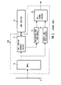
- FIG. 1 An application system of the present invention is illustrated in Fig. 1.
- the system involves a host processor 1, a coding/decoding circuit 2, an image printer 3, a CRT display device 4, a main memory 5 having an image memory area 10, a scanner 6, a communication controller 7 having a transmitter and a receiver, and a disk unit 8 which are coupled by a system bus 9 to each other.
- This system is used as a facsimile machine and/or an image work station.
- the coded signals received at the communication controller 7 are decoded into original facsimile signals and are printed out by the image printer 3 or are displayed on a screen of the CRT 4. Further, the decoded facsimile signals may be recorded in the disk unit 8. To code or decode the facsimile signals the coding/decoding circuit 2 is employed.
- Fig. 2 illustrates an internal block diagram of the conventional coding circuit which includes a well-known MR coding circuit 15.
- the MR coding circuit 15 is a two-dimensional coding circuit.
- the present invention relates to a preparation circuit of the MR coding, so that a detailed explanation with respect to the MR coding circuit will be omitted.
- adjacent two lines are necessary as described hereinbefore.
- a line to be coded is transferred word by word via a coding line FIFO (First-In-First-Out) circuit 14 to the MR coding circuit 15, while a reference line is transferred word by word via a reference line FIFO circuit 13 to the MR coding circuit 15.
- FIFO First-In-First-Out
- DMAC direct memory access controller
- the line buffering technology is based on the view that a line to be coded is used as a reference line when a successive line is coded.
- DMAC 16 enters a line to be coded which is read out of the image memory area 10 into the coded line FIFO circuit and enters it into a line buffer control circuit 11 at the same time.
- the line buffer control circuit 11 has a first address circuit generating a write-address at which the line to be coded is written and a second address circuit generating a read-address from which the line is read out.
- the line buffer control circuit 11 applies the line transferred from the DMAC 16 to a line buffer 12 together with the write address.
- the line buffer 12 temporarily stores the line applied from the line buffer control circuit.
- the stored line is read out of the line buffer 12 according to the read address and is entered into the reference line FIFO circuit 13 when a subsequent line to be coded is entered into the coded line FIFO circuit 14.
- the buffer 12 should have a large memory capacity (3456 bits x 2 in the case of A4 size when 1 mm is scanned by 16 scanning signals.) Consequent by, it is difficult to integrate the line buffer 12 on a single semiconductor chip 100 on which the two FIFO circuits 13 and 14, the MR coding circuit 15 and the DMAC 16 are formed.
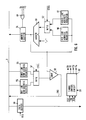
- the coding circuit employing MR coding algorithm shown in Fig. 3 comprises a direct memory access controller (DMAC) 20, a line buffer control circuit 21, a line buffer 22, a reference line FIFO circuit 23, a coded line FIFO circuit 24, an MR coding circuit 25 and a preparation circuit 26.
- the feature of the present invention is in the preparation circuit 26 which has a compression circuit 27 and an expansion circuit 28.
- the DMAC 20 and the line buffer control circuit 21 are slightly modified as described hereinafter.
- the reference line FIFO circuit 23, the coded line FIFO circuit 24 and the MR coding circuit 25 may be the same as those in Fig. 2. With respect to the line buffer 22, its capacity can be remarkably reduced.
- the DMAC 20 is coupled to the system bus 9 for access of the main memory 5 in Fig.1 and is coupled to the reference line FIFO circuit 23, the coded line FIFO circuit 24 and the preparation circuit 26 in common.
- the compression circuit 27 receives a line to be coded which is entered into the coded line FIFO circuit 24 and compresses the line into a short code (hereinafter called "compression code") LX.
- the compression code LX is written into the line buffer 22 via the line buffer control circuit 21.
- the compression code stored in the line buffer 22 is read out and sent to the expansion circuit 28 as a reference code LW by the line buffer control circuit 21.
- the expansion circuit 28 expands the reference code LW to reproduce the original line by using the DMAC 20.
- the reproduced line is entered into the reference line FIFO circuit 23 as a reference line, when a successive line to be coded is entered into the coded line FIFO circuit 24, adjacent two lines are applied to the MR coding circuit 25 from the FIFO circuits 23 and 24.
- the MR coding circuit 25 produces a coded signal of the line in the coded line FIFO circuit 24 with reference to the line in the reference line FIFO circuit 23 according to the MR coding algorithm.
- the DMAC 20 can access the image memory area10 of the main memory 5 word by word.
- one word is comprised of 16 bits (dots)
- the DMAC 20 simultaneously read 16 bits out of the image memory area 10 and entered into the compression circuit 27 and the coded line FIFO circuit 24 at the same time.
- the compression circuit 27 compresses the read out 16 bits into one bit (compression code). That is, if the 16 bits represent all white picture elements, "0" is generated as the compression code. On the other hand, if the 16 bits include at least one black picture element, "1" is generated as the compression code.
- the compression circuit 27 compresses 16 bits into one bit.
- the compressed code is written into the line buffer 22. Consequently, a capacity of the line buffer 22 can be reduced to one-sixteenth.
- the line buffer 22 can be integrated on a single semiconductor chip 200 together with the DMAC 20, the preparation circuit 26 and FIFO circuit 23 and 24.
- the illustrated compression circuit comprises an OR gate 30 coupled its 16 input ends to the DMAC 20 and receiving 16 bits D0 - D15 in parallel at the 16 input ends, respectively, and a flip-flop 31 coupled its set input end to an output of the OR gate 30. It is assumed that a white picture element is represented by "0" and that a black picture element is represented by "1". When the 16 bits of D0 - D15 are all white picture elements, an output of the OR gate 30 becomes “0". The flip-flop 31 is set to "0” and outputs "0" signal as the compression code LX.
- the code written into the line buffer 22 must be used as the reference line when a subsequent line is coded.
- the reference line is written into the line buffer 22 in the form of the compression code, so that the compression code read out of the line buffer 22 can not be entered into the reference line FIFO circuit 23 at it is. Therefore, the expansion circuit 28 is provided to expand the compression code into 16-bit signals before compression.
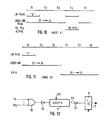
- Fig. 5 illustrates a circuit diagram of an example of the expansion circuit 28.
- the expansion circuit has a white picture element signal generator.
- 16-bit white signals (“0" signals) are generated according to the compression code LW read out of the line buffer 22.
- 16 buffers B0 - B15 are arranged in parallel. An input end of each buffer is connected to ground (GNP) in common.
- the compression code LW read out of the line buffer 22 is applied to those 16 buffers B0 - B15 in common.
- the buffers B0 - B15 are activated simultaneously when the compression code LW is "0" (low level signal) and generate 16 of "0" signals D0 - D15 at the same time.
- These "0" signals represent 16 bits of white picture elements and are transferred to the reference line FIFO circuit 23. That is, when the LW is "0", 16 bits to be entered into the reference line FIFO circuit 23 are all white signals. Therefore, the expansion circuit 28 produces 16 bits of white signals ("0" signals).
- the expansion circuit 28 has a control circuit comprising OR gates 34 and 36, an AND gate 33, an inverter 35 and a T type flip-flop 32.
- the control circuit receives timing signals S3 and S4 and the compression code LW read out of the line buffer 22 and produces a request signal REQ when the LW is "1".
- the request signal REQ is applied to the DMAC 20 to indicate that the previous line which has been already coded is required as the reference line.
- the DMAC 20 read the previous line stored in the image memory area 10 out of the main memory 5 by means of the DMA transfer only when the LW is "1".
- the previous line including at least one black picture element is entered into the reference line FIFO circuit 23.
- the REQ signal is generated when a CSEL signal is "1", or when both the signal and the LW are "1".
- the CSEL signal is an output signal of the flip-flop 32 whose state is changed whenever either the S3 signal or the S4 signal becomes "1".
- the DMAC 20 comprises a DMA address generating circuit having a reference line address register 50, a coded line address register 51, a multiplexer 52, an adder 53, and an address buffer 54, a control circuit having a reference line end address register 55, a coded line end address register 56, a multiplexer 57 and a comparator 58, a data transmission circuit having a data buffer 59, and a timing control circuit having a circuit 60.
- the DMAC 20 has to be able to read both the line to be coded and the line to be used as the reference line out of the image memory area 10.
- the DMA address generating circuit generates the coded line address and the reference line address alternatively.
- the coded line address is applied via the MPX 52 from the register 51 to the adder 53 and is added by one.
- the added coded line address is sent through the system bus 9 to the main memory 5 via the address buffer 54 to read the line to be coded out of the image memory area 10 and is also fed back to the register 51.
- the CSEL signal is "0"
- the reference address is applied via the MPX 52 from the reference address register 50 to the adder 53 and is added by one.
- the added reference line address is fed back to the register 50. Further this address is sent through the system bus 9 to the main memory 5 to read the reference line out of the image memory area 10 only when the LW signal is "1".
- the line read out of the main memory 5 is transferred through the system bus 9 to the data buffer 59 which is activated when the REQ signal is "1".
- the data buffer 59 is activated, the line to be coded read out of the main memory 5 is entered to the coded line FIFO circuit 26 and the compression circuit 27 and the line to be used as the reference line is entered into the reference line FIFO circuit 23.
- the reference line end address and the coded line end address are set by the host processor 1 and are compared with the output of the adder.
- the coded line end address is compared with the coded line address
- the reference line end address is compared with the reference line address.
- the coincidence signal is sent to the host processor 1 as an DMA end signal through the system bus 9.
- the DMA transfer is controlled by timing signals S1 to S4 generated by the timing control circuit 60 in response to the signal, the signal and the REQ signal.
- An internal block diagram of the timing control circuit 60 is shown in Fig. 7.
- the timing control circuit 60 has four delay type flip-flops (DFF) 61 to 64 which are linked together in this order, and receive a clock CK in common.
- An output of an OR gate 68 is applied to an input end of the DFF 61.
- An output of the DFF 61 is the S1 signal and is applied to an input end of the DFF 62 whose output is the S2 signal and is applied to an input end of the DFF 63.
- An output of the DFF 63 is the S3 signal and is applied to AND gates 66 and 67.
- the AND gate 66 further receives an output of an AND gate 65 which becomes “1" when the and signals are both “1".
- the AND gate 67 becomes “1” when the S3 signal and the REQ signal are both "1".
- the last DFF 64 receives the output of the AND gate 66 and generates the S4 signal.
- the S4 signal and the output of the AND gate 67 are fed back to the input of the DFF 61 via the OR gate 68.
- the timing control circuit 60 shown in Fig. 7 is set such that the S1 signal is activated when the circuit 60 is initialized by a reset signal. Thereafter the S1 signal and the S2 signal are generated sequentially in this order in response to the clock. A period between S1 to S3 is assigned to perform a DMA transfer, that is either a line to be coded or a line used as a reference line is read out of the main memory 5. Therefore, the address buffer 54 of Fig. 6 is activated by the S1, S2 or S3 signal. When the DMA transfer is required, the S1 to S3 signals are sequentially generated.
- the S4 signal is generated if the compression code LW read out of the line buffer 22 is "0". That is, when the compression code is "0", the expansion circuit 28 produces 16-bit of all white signal, so that the DMA transfer of the reference line is not required. In this case, the signal and the signal become both "1". Thus the AND gate 66 generates "1" signal. In response to the output of the AND gate 66 the DFF 64 produces the S4 signal. It should be noted that the expansion circuit 28 can generate the 16-bit of white signals within a period determined by only the S4 signal because the DMA transfer is unnecessary.
- the expansion circuit 28 can not produce the reference line. Therefore, the REQ signal is generated to indicate the DMA transfer to the DMAC 20. At this time, since the AND gate 67 becomes "1", the S1 signal is generated after the S3 signal has been generated. The S4 signal is not generated at this time.
- Fig. 8 illustrates internal block diagrams of the line buffer control circuit 21 and the line buffer 22 in Fig. 3.
- the line buffer control circuit 21 has a write address generation circuit 44 and a read address generation circuit 45.
- the line buffer 22 has two line buffer memories A 46 and B 47.
- the compression code LX applied from the compression circuit 27 is written into the line buffer memory A 46 via a multiplexer 40 according to a write address applied to the line buffer memory A 46 via a multiplexer 41
- the compression code already stored in the line buffer memory B 47 is read out via a multiplexer 42 as the reference code LW according to a read address applied to the line buffer memory B 47 via a multiplexer 43 and vice versa.
- Multiplexers 40 to 43 are controlled by a switching control circuit 48.
- a capacity of each line buffer memory is enough 216 bits, respectively.
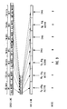
- Fig. 9 shows compression of a line and expansion of compression codes.
- 1st block to 7th block of a line is illustrated. Each block consists of 16 bits.
- 1st, 2nd, 3rd and 6th blocks are all white picture elements, while 4th, 5th and 7th blocks include at least one black picture element, respectively.
- the 1st block is read out of the main memory 5
- the 1st block is applied to the coded line FIFO circuit 24 and the compression circuit 26. Since this 1st block has all white picture elements, the compression circuit 27 produces a compression code "0". Subsequently, the 2nd and 3rd blocks are compressed into the compression code "0", respectively.
- the 4th and 5th blocks are compressed into “1”, respectively.
- the 6th block and the 7th block are compressed into “0” and “1”, respectively.
- 112 bits are compressed into 7 bits.
- the compression codes are read out of the line buffer 22 and are used to prepare a reference line.
- the expansion circuit 28 produces white picture element signals.
- the reference line information corresponding to the 1st, 2nd, 3rd and 6th blocks are produced by the expansion circuit 28 and are entered into the reference line FIFO circuit 23.
- the compression code is read out of the line buffer 22 in response to the S1 signal and a line to be coded is read out of the main memory 5 in response to the S1 to S3 signal.
- the compression code is "0", so that the S4 signal is generated.
- the expansion circuit 28 produces white picture element signals and enters them into the reference line FIFO circuit 23.
- the compression codes of the 4th, 5th and 7th blocks are "1", and therefore the reference line is produced by a mode B as shown in Fig. 11.
- the compression code "1" is read out of the line buffer 22 in response to the S1 signal and the line to be coded is read out of the main memory 5 in response to the S1 to S3 signals. Since the compression code is "1", the timing control circuit 60 does not generated the S4 signal but generated the S1 to S3 signal to allow the DMA transfer. Then, the DMAC 20 reads the reference line information corresponding to the 4th, 5th and 7th blocks out of the main memory 5 and enters them to the reference line FIFO circuit 23.
- the line buffer can be integrated on a single semiconductor chip together with the DMAC, the MR coding circuit, the FIFO circuits and the preparation circuit. Further, since the number of the black picture element is smaller than that of the white picture elements, MR coding can be performed at a high speed.
- the compression circuit 27 compresses one block consisting of 16 bits into one bit.
- the compression circuit can be modified as shown in Fig. 12.
- a counter 71 is inserted between the OR gate 30 and the flip-flop 31.
- the output of the OR gate 30 is applied to the counter 71 as a count-up signal via an inverter 70.
- the counter 71 is a 3-bit up counter, a carry signal CA is generated when continuous 8 blocks are all white picture elements.
- "0" is set to the flip-flop 31 via an inverter 72.
- the carry signal CA is not generated.
- "1" is set to the flip-flop 31.
- 16 x 8 128 bits are compressed into one bit according to Fig. 12. Therefore, a capacity of the line buffer can be further reduced.
- Fig. 13 illustrates another embodiment of the present invention which is applied to MR decoding circuit.
- a coded signal to be decoded is received to the communication controller 7 and is stored in the main memory 5 line by line by the host processor 1.
- the stored signal is entered into the MR decoding circuit 80 by the DMAC 20 via the reference line FIFO circuit 23 and the decoded line FIFO circuit 81.
- the decoded line derived from the MR decoding circuit 80 is written into the image memory area 10 of the main memory 5 and is also transferred to the compression circuit 27.
- the compression operation is the same operation as that of the coding as shown in Fig. 4 or 12.
- the decoded line is used as the reference line when the successive line is decoded.
- the decoded line is compressed into the compression code and is stored in the line buffer 22 through the line buffer control circuit 21.
- the compression code in the line buffer 22 is read out of the line buffer 22 and is applied to the expansion circuit 28.
- the expansion operation is the same operation as that of coding as shown in Fig. 5.
- the preparation circuit can be used to MR decoding operation.
- the line buffer 22 can be integrated on a single semiconductor chip 300 with the DMAC 20, the line buffer control circuit 21, the compression and expansion circuits 27 and 28, FIFO circuits 23 and 81 and the MR decoding circuit 80.
- the present invention can be applied to MMR coding/decoding.
Landscapes
- Engineering & Computer Science (AREA)
- Multimedia (AREA)
- Signal Processing (AREA)
- Compression Of Band Width Or Redundancy In Fax (AREA)
Applications Claiming Priority (2)
| Application Number | Priority Date | Filing Date | Title |
|---|---|---|---|
| JP28957085 | 1985-12-23 | ||
| JP289570/85 | 1985-12-23 |
Publications (2)
| Publication Number | Publication Date |
|---|---|
| EP0229379A2 true EP0229379A2 (fr) | 1987-07-22 |
| EP0229379A3 EP0229379A3 (fr) | 1989-12-20 |
Family
ID=17744938
Family Applications (1)
| Application Number | Title | Priority Date | Filing Date |
|---|---|---|---|
| EP86117957A Withdrawn EP0229379A3 (fr) | 1985-12-23 | 1986-12-23 | Circuit pour coder/décoder des signaux d'image numériques |
Country Status (3)
| Country | Link |
|---|---|
| US (1) | US4800440A (fr) |
| EP (1) | EP0229379A3 (fr) |
| JP (1) | JPS62230164A (fr) |
Cited By (1)
| Publication number | Priority date | Publication date | Assignee | Title |
|---|---|---|---|---|
| EP2031856A1 (fr) * | 2007-08-31 | 2009-03-04 | Canon Kabushiki Kaisha | Dispositif et procédé de décodage d'image |
Families Citing this family (11)
| Publication number | Priority date | Publication date | Assignee | Title |
|---|---|---|---|---|
| JPH05122537A (ja) * | 1991-10-30 | 1993-05-18 | Nec Ic Microcomput Syst Ltd | 二次元符号化装置 |
| US6170047B1 (en) * | 1994-11-16 | 2001-01-02 | Interactive Silicon, Inc. | System and method for managing system memory and/or non-volatile memory using a memory controller with integrated compression and decompression capabilities |
| US6002411A (en) | 1994-11-16 | 1999-12-14 | Interactive Silicon, Inc. | Integrated video and memory controller with data processing and graphical processing capabilities |
| JP4834362B2 (ja) * | 2005-09-16 | 2011-12-14 | パナソニック株式会社 | メモリ制御装置。 |
| JP3732702B2 (ja) * | 2000-01-31 | 2006-01-11 | 株式会社リコー | 画像処理装置 |
| JP2001339719A (ja) * | 2000-05-24 | 2001-12-07 | Thine Electronics Inc | ディジタル画像伝送用符号化器 |
| DE60309588T2 (de) * | 2003-08-11 | 2007-09-13 | Seiko Epson Corp. | Eine Datenübertragungsvorrichtung zur Übertragung von Flüssigkeitsausstossdaten und eine Flüssigkeitsausstossvorrichtung |
| CN1306825C (zh) * | 2004-07-29 | 2007-03-21 | 联合信源数字音视频技术(北京)有限公司 | 视频解码芯片中基于行缓冲的参考存储方法 |
| JP5131150B2 (ja) * | 2008-10-27 | 2013-01-30 | 富士ゼロックス株式会社 | 符号化装置、復号装置、及び画像処理システム |
| US10324842B2 (en) * | 2014-12-13 | 2019-06-18 | Via Alliance Semiconductor Co., Ltd | Distributed hang recovery logic |
| EP3066559B1 (fr) * | 2014-12-13 | 2019-05-29 | VIA Alliance Semiconductor Co., Ltd. | Analyseur logique de détection de blocages |
Family Cites Families (6)
| Publication number | Priority date | Publication date | Assignee | Title |
|---|---|---|---|---|
| JPS53128214A (en) * | 1977-04-15 | 1978-11-09 | Toshiba Corp | Encoding transmission device for facsimile signal |
| US4396952A (en) * | 1981-07-06 | 1983-08-02 | Tisue James G | Facsimile transmission apparatus |
| JPS58151769A (ja) * | 1982-03-05 | 1983-09-09 | Ricoh Co Ltd | ファクシミリ装置 |
| US4486784A (en) * | 1982-12-27 | 1984-12-04 | International Business Machines Corporation | Image compression systems |
| NL8301264A (nl) * | 1983-04-11 | 1984-11-01 | Philips Nv | Inrichting voor het regelsgewijs comprimeren van binaire data van een beeldveld- en aftastinrichting voor een document voorzien voor zulk comprimeren. |
| JPH0783427B2 (ja) * | 1984-04-03 | 1995-09-06 | キヤノン株式会社 | 画像伝送方法 |
-
1986
- 1986-12-23 EP EP86117957A patent/EP0229379A3/fr not_active Withdrawn
- 1986-12-23 JP JP61314851A patent/JPS62230164A/ja not_active Withdrawn
- 1986-12-23 US US06/946,434 patent/US4800440A/en not_active Expired - Lifetime
Cited By (2)
| Publication number | Priority date | Publication date | Assignee | Title |
|---|---|---|---|---|
| EP2031856A1 (fr) * | 2007-08-31 | 2009-03-04 | Canon Kabushiki Kaisha | Dispositif et procédé de décodage d'image |
| US8351719B2 (en) | 2007-08-31 | 2013-01-08 | Canon Kabushiki Kaisha | Image decoding apparatus, image decoding method, and printing apparatus |
Also Published As
| Publication number | Publication date |
|---|---|
| EP0229379A3 (fr) | 1989-12-20 |
| JPS62230164A (ja) | 1987-10-08 |
| US4800440A (en) | 1989-01-24 |
Similar Documents
| Publication | Publication Date | Title |
|---|---|---|
| US4091424A (en) | Facsimile compression system | |
| EP0229379A2 (fr) | Circuit pour coder/décoder des signaux d'image numériques | |
| US4922437A (en) | Image information processing apparatus | |
| JPH04199981A (ja) | 即時処理型1次元符号器 | |
| JPH06274612A (ja) | 画像処理装置 | |
| US5579412A (en) | Image processing apparatus | |
| US4955061A (en) | Method and apparatus for processing an image signal | |
| US5825692A (en) | Memory system and method for simultaneously reading and writing data | |
| JP2002077637A (ja) | 画像符号化装置及び画像符号化方法 | |
| JP2933029B2 (ja) | デジタル信号符号化/復号化回路 | |
| JPS5883473A (ja) | 画信号符号化方式 | |
| JPS6341276B2 (fr) | ||
| JPS60119170A (ja) | ファクシミリ接続装置 | |
| JPH0352714B2 (fr) | ||
| JP3313463B2 (ja) | 画像処理装置 | |
| JPH03136575A (ja) | ファクシミリ符号器 | |
| JP2941574B2 (ja) | 高速伸張処理装置 | |
| JPH0844875A (ja) | 符号化処理装置 | |
| JPS6132867B2 (fr) | ||
| JPH02240773A (ja) | 画像処理装置 | |
| JPS61256868A (ja) | デ−タ処理方式 | |
| JPH04160573A (ja) | 画像データ変換装置 | |
| JPH0286267A (ja) | 半導体メモリ | |
| JPH03187564A (ja) | ファクシミリ装置 | |
| JPS6219978A (ja) | デ−タ処理装置 |
Legal Events
| Date | Code | Title | Description |
|---|---|---|---|
| PUAI | Public reference made under article 153(3) epc to a published international application that has entered the european phase |
Free format text: ORIGINAL CODE: 0009012 |
|
| 17P | Request for examination filed |
Effective date: 19861223 |
|
| AK | Designated contracting states |
Kind code of ref document: A2 Designated state(s): DE FR GB |
|
| PUAL | Search report despatched |
Free format text: ORIGINAL CODE: 0009013 |
|
| AK | Designated contracting states |
Kind code of ref document: A3 Designated state(s): DE FR GB |
|
| 17Q | First examination report despatched |
Effective date: 19911031 |
|
| STAA | Information on the status of an ep patent application or granted ep patent |
Free format text: STATUS: THE APPLICATION HAS BEEN WITHDRAWN |
|
| 18W | Application withdrawn |
Withdrawal date: 19920410 |
|
| RIN1 | Information on inventor provided before grant (corrected) |
Inventor name: KUROKAWA, HIDEFUMIC/O NEC CORPORATION |