EP0237490A2 - Butées de positionnement et montage d'usinage pour le serrage de pièces - Google Patents
Butées de positionnement et montage d'usinage pour le serrage de pièces Download PDFInfo
- Publication number
- EP0237490A2 EP0237490A2 EP19870810174 EP87810174A EP0237490A2 EP 0237490 A2 EP0237490 A2 EP 0237490A2 EP 19870810174 EP19870810174 EP 19870810174 EP 87810174 A EP87810174 A EP 87810174A EP 0237490 A2 EP0237490 A2 EP 0237490A2
- Authority
- EP
- European Patent Office
- Prior art keywords
- stop
- plate
- unit
- stop unit
- workpiece
- Prior art date
- Legal status (The legal status is an assumption and is not a legal conclusion. Google has not performed a legal analysis and makes no representation as to the accuracy of the status listed.)
- Granted
Links
Images
Classifications
-
- B—PERFORMING OPERATIONS; TRANSPORTING
- B25—HAND TOOLS; PORTABLE POWER-DRIVEN TOOLS; MANIPULATORS
- B25B—TOOLS OR BENCH DEVICES NOT OTHERWISE PROVIDED FOR, FOR FASTENING, CONNECTING, DISENGAGING, OR HOLDING
- B25B5/00—Clamps
- B25B5/06—Arrangements for positively actuating jaws
- B25B5/10—Arrangements for positively actuating jaws using screws
- B25B5/104—Arrangements for positively actuating jaws using screws with one screw and one clamping lever and one fulcrum element
-
- B—PERFORMING OPERATIONS; TRANSPORTING
- B23—MACHINE TOOLS; METAL-WORKING NOT OTHERWISE PROVIDED FOR
- B23Q—DETAILS, COMPONENTS, OR ACCESSORIES FOR MACHINE TOOLS, e.g. ARRANGEMENTS FOR COPYING OR CONTROLLING; MACHINE TOOLS IN GENERAL CHARACTERISED BY THE CONSTRUCTION OF PARTICULAR DETAILS OR COMPONENTS; COMBINATIONS OR ASSOCIATIONS OF METAL-WORKING MACHINES, NOT DIRECTED TO A PARTICULAR RESULT
- B23Q3/00—Devices holding, supporting, or positioning work or tools, of a kind normally removable from the machine
- B23Q3/02—Devices holding, supporting, or positioning work or tools, of a kind normally removable from the machine for mounting on a work-table, tool-slide, or analogous part
- B23Q3/10—Auxiliary devices, e.g. bolsters, extension members
- B23Q3/103—Constructional elements used for constructing work holders
-
- B—PERFORMING OPERATIONS; TRANSPORTING
- B25—HAND TOOLS; PORTABLE POWER-DRIVEN TOOLS; MANIPULATORS
- B25B—TOOLS OR BENCH DEVICES NOT OTHERWISE PROVIDED FOR, FOR FASTENING, CONNECTING, DISENGAGING, OR HOLDING
- B25B5/00—Clamps
- B25B5/16—Details, e.g. jaws, jaw attachments
Definitions
- the invention relates to a stop unit with a support block, attachment means for the workpiece, a clamping bracket and means for clamping the bracket, for use on a base plate in the form of a perforated plate, groove plate, pallet or the like for positioning and clamping workpieces to be machined,
- the support block has a support surface for the workpiece at the top and a flat base surface for support on the base plate and alignment means are provided for aligning the support block on the base plate.
- kits have been used for a long time, which consist, for example, of a perforated grid plate, a number of stop units, a number of support units and at least one clamping unit.
- a perforated grid plate for example, a perforated grid plate, a number of stop units, a number of support units and at least one clamping unit.
- a flat, rectangular workpiece can be placed on three or four support units, struck against two stop units and clamped with a clamping unit. All of these units are attached to the grid plate.
- the stop units can be adjusted by screws, the exact setting being made with a dial gauge.
- the disadvantage of this system is the relatively long set-up times.
- the stop unit or the other units of a kit should be able to be combined in many ways and used again and again. In particular, however, the set-up times are to be greatly reduced.
- the stop surface is formed by a surface of the support block which is aligned parallel to the direction of the alignment means. Since the support block is a rigid structure and after fastening to the base plate, e.g. a perforated grid plate or cross groove plate, is aligned with the usual dowel pins or sliding blocks with a tolerance of less than 0.02 mm, the stop surface is located in relation to the perforated grid system or groove system always precisely aligned. As a result, there is no need to adjust the stops with dial indicators. This greatly shortens the set-up time. With the precise definition of the stop surface, the area is also defined within which the clamping bracket can move.
- the stop surface is advantageously in the same plane as the axis on which the alignment means are arranged.
- the alignment means can, for example, through two fitting holes for receiving fitting means, e.g. Fit screws, be formed for a perforated grid plate.
- fitting means e.g. Fit screws
- the stop surface always comes to lie vertically over a grid line of the perforated grid plate.
- the alignment means are formed by a sliding block. In this case, the stop surface always comes to lie over the central axis of a groove of the cross groove plate.
- the alignment means are advantageously formed by four fitting bores, two of which have axes which lie in the same plane as the stop surfaces, while the remaining two fitting bores have axes which are parallel to one another in a plane, the center distances being the grid dimension or a multiple thereof correspond.
- the invention also relates to a kit for clamping workpieces consisting of a base plate, at least one stop unit according to one of claims 1 to 5 and at least one adjusting unit.
- a kit for clamping workpieces consisting of a base plate, at least one stop unit according to one of claims 1 to 5 and at least one adjusting unit.
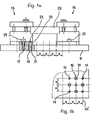
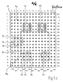
- the kit shown in Figures la, lb and lc comprises at least one base plate, e.g. a perforated grid plate 11, at least one stop unit 13 and at least one adjusting unit 15.
- a perforated grid plate 11 there are a large number of bores 17, 19 with a grid spacing R, e.g. 50 mm.
- the bores 17 are threaded bores; the holes 19 contain a hardened steel sleeve 21.
- perforated grid plates are also commercially available which have a steel sleeve 21 in the upper part of each hole and are provided with a thread in the lower part.
- a pin 23 can be inserted into the bushing 21, which also fits exactly into the bores 25 of the stop unit 13.
- the position of the stop unit 13 on the perforated grid plate 11 is precisely determined by pins 23.
- the stop and adjusting units 13, 15 are fastened to the perforated grid plate by means of screws 27.
- a pallet could also serve to accommodate the stop and adjusting units 13, 15.
- the base plate 11 can also be designed as a cross groove plate.
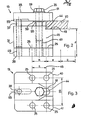
- the stop unit 13 essentially consists of the support block 31, the clamping bracket 33, the clamping screw 35 and the support screw 37 for the clamping bracket 33.
- the support block 31 has a flat ground base 39 for resting on the base plate.
- the support surface 43 for the workpiece 29, which is arranged parallel to this base surface 39, is located at a distance h from the base surface 39.
- the stop surface 44 is provided for the lateral stop of the workpiece 29. It is of particular importance that the stop surface 44 arranged perpendicular to the base surface 39 is arranged parallel to the center line 45 of two bores 25. As a result, the stop surface 44 also runs parallel to a line 45 ′, which represents a line of the hole grid, after the stop unit 13 has been installed on the perforated grid plate 11. In the exemplary embodiment shown according to FIGS. 2 and 3, the abutment surface 44 not only runs parallel to line 45, but also lies in the same plane as this line 45.
- the abutment surface 44 also lies in the lies on the same level as a corresponding raster line 45 '. In this way, in the case of numerically controlled machines, the workpiece zero point of a machining axis can be determined in a simple manner, which leads to a considerable reduction in the setting time.
- the support block 31 has a threaded bore 47 or threaded bush for the clamping screw 35 and a threaded bore 49 for the support screw 37.
- the tensioning strap 33 has a slot 51, which restricts the movement of the tensioning strap in the longitudinal direction by a package prevent danger of sion with tools of the machine tool.
- a groove 53 serves to receive the upper part of the support screw 37.
- the clamping screw 35 is prevented from falling out of the clamping bracket 33 by a circlip 55.
- With the reference numerals 57 and 59 washers are designated.
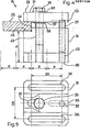
- the application unit 15 according to FIGS. 4 and 5 are basically of the same design as the stop unit 13 described above, but instead of the fitting bores 25, they have two slots 26, which allow the adjusting unit 15 to be displaced on the base plate 11.
- the almost identical design of the stop unit and application unit gives considerable advantages for their manufacture.
- the perforated grid plate 11 shown there has a grid spacing of 50 mm.
- the horizontal rows of holes are labeled with consecutive numbers and the vertical rows of holes with letters in alphabetical order. Since the perforated plate 11 is always inserted into the machine in exactly the same way, using dowel pins to determine the exact position, the machine zero point M o is always at the same location, in the example shown at C3.
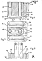
- a support block 31 is described in FIGS. 6 to 8, which is specially designed for use with cross groove plates.
- the support block 31 has a transverse groove 61 and a longitudinal groove 63.
- sliding blocks 65 and 66 can be inserted.
- a particular advantage of this embodiment is that the stop unit and adjusting unit are basically of the same design. Both units have slots 26. Each stop unit becomes a positioning unit when the sliding block 65 is removed. After removal of the sliding block 65, the unit is namely displaceable in the longitudinal direction.
- stop surface 44 is aligned parallel to the direction of the alignment means, in this case the groove 61 and thus also the sliding block 65. This inevitably means that the stop surface 44 also runs parallel to the groove in a groove plate in which the sliding block 65 engages.
- the stop surface 44 is also in the same plane as the center line 45 of the groove 61 or the sliding block 65. As a result, the stop surface 44 is always in the same plane as the corresponding grid line of the cross-groove plate.
- stop or adjusting unit is of the same design as that of FIGS. 2 and 5, so that reference can be made to the description there.
Landscapes
- Engineering & Computer Science (AREA)
- Mechanical Engineering (AREA)
- Jigs For Machine Tools (AREA)
- Electrical Discharge Machining, Electrochemical Machining, And Combined Machining (AREA)
- Load-Engaging Elements For Cranes (AREA)
- Conveying And Assembling Of Building Elements In Situ (AREA)
- Jib Cranes (AREA)
Priority Applications (1)
| Application Number | Priority Date | Filing Date | Title |
|---|---|---|---|
| AT87810174T ATE63491T1 (de) | 1986-03-27 | 1987-03-26 | Anschlageinheit und bausatz zum spannen von werkstuecken. |
Applications Claiming Priority (2)
| Application Number | Priority Date | Filing Date | Title |
|---|---|---|---|
| CH1257/86 | 1986-03-27 | ||
| CH125786 | 1986-03-27 |
Publications (3)
| Publication Number | Publication Date |
|---|---|
| EP0237490A2 true EP0237490A2 (fr) | 1987-09-16 |
| EP0237490A3 EP0237490A3 (en) | 1987-10-21 |
| EP0237490B1 EP0237490B1 (fr) | 1991-05-15 |
Family
ID=4206154
Family Applications (1)
| Application Number | Title | Priority Date | Filing Date |
|---|---|---|---|
| EP87810174A Expired - Lifetime EP0237490B1 (fr) | 1986-03-27 | 1987-03-26 | Butées de positionnement et montage d'usinage pour le serrage de pièces |
Country Status (4)
| Country | Link |
|---|---|
| EP (1) | EP0237490B1 (fr) |
| AT (1) | ATE63491T1 (fr) |
| DE (1) | DE3770029D1 (fr) |
| ES (1) | ES2022445B3 (fr) |
Cited By (11)
| Publication number | Priority date | Publication date | Assignee | Title |
|---|---|---|---|---|
| EP0342256A1 (fr) * | 1988-05-19 | 1989-11-23 | 3R Management ab | Butoir avec des trous de centrage |
| WO1990000955A1 (fr) * | 1988-07-19 | 1990-02-08 | Büchler B-Set Ag | Palette |
| EP0356717A3 (fr) * | 1988-09-02 | 1990-08-29 | Hans Kolbe & Co. | Table de support pour empilements de circuits imprimés destinés à être percés |
| WO1990010523A1 (fr) * | 1987-09-09 | 1990-09-20 | Ferd. Rüesch Ag | Dispositif de serrage |
| EP0497193A3 (en) * | 1991-01-29 | 1992-10-07 | Saurer-Allma Gmbh | Mounting device and workpiece clamp |
| FR2679814A1 (fr) * | 1991-07-30 | 1993-02-05 | Vallemagne Cie | Dispositif de bridage de pieces sur table de machine-outil. |
| EP0637482B2 (fr) † | 1993-08-05 | 2005-03-23 | Erowa AG | Procédé de positionnement d'un porte-pièce dans une machine d'usinage, ainsi que porte-pièce correspondant |
| CN102390021A (zh) * | 2011-08-17 | 2012-03-28 | 浙江大学 | 专用组合机床的工件夹紧装置 |
| CN102601643A (zh) * | 2012-03-07 | 2012-07-25 | 苏州工业园区艺达精密机械有限公司 | 多工件夹紧装置 |
| CN102922330A (zh) * | 2012-11-13 | 2013-02-13 | 如皋市同泰电力器材有限公司 | 一种隔离开关熔断器金具加工工装 |
| CN108274255A (zh) * | 2018-03-20 | 2018-07-13 | 强胜精密机械(苏州)有限公司 | 一种多工位弹簧单螺纹复合工装装置及装夹方法 |
Families Citing this family (7)
| Publication number | Priority date | Publication date | Assignee | Title |
|---|---|---|---|---|
| DE4207437C2 (de) * | 1992-03-09 | 1994-02-03 | Georg Kraeutner | Spannvorrichtung |
| DE10214328A1 (de) * | 2002-03-28 | 2003-10-16 | Thomas Herbert Drittenpreis | Vorrichtung für die Aufnahme von zu bearbeitenden Werkstücken |
| CN101623772B (zh) * | 2009-08-13 | 2011-08-31 | 沈阳飞机工业(集团)有限公司 | 用于孔系组合夹具的中孔支承板 |
| DE102015013543A1 (de) | 2015-10-19 | 2017-04-20 | Audi Ag | Verstelleinheit |
| CN105269372A (zh) * | 2015-10-27 | 2016-01-27 | 芜湖市泰能电热器具有限公司 | 一种可控式批量工件铣端面夹具 |
| DE102017103776B3 (de) | 2017-02-23 | 2018-08-02 | Aweba Werkzeugbau Gmbh Aue | Positioniersystem für Werkstück-Spannkomponenten |
| CN107900664A (zh) * | 2017-11-29 | 2018-04-13 | 西南石油大学 | 一种生锈螺栓在线更换装置 |
Family Cites Families (7)
| Publication number | Priority date | Publication date | Assignee | Title |
|---|---|---|---|---|
| CH250142A (fr) * | 1945-04-18 | 1947-08-15 | Schuetz & Co E | Chien de serrage. |
| DE1602912B2 (de) * | 1967-09-29 | 1974-03-07 | Otto 8000 Muenchen Oeckl | Verfahren zum Positionieren eines Werkstückes auf dem Werkstücktisch einer Werkzeugmaschine und Vorrichtung zur Durchführung dieses Verfahrens |
| FR2267856A1 (en) * | 1974-04-22 | 1975-11-14 | Moussion Jean | Workpiece holder for machine tool - has support blocks with adjustable stop pins and clamps |
| DE2537146C3 (de) * | 1975-08-21 | 1980-05-14 | Hubert Dipl.-Ing. 5820 Gevelsberg Bald | Baueinheit aus zwei in eine Relativlage zu positionierenden Bauteilen |
| CH624329A5 (en) * | 1977-11-08 | 1981-07-31 | Bald Hubert | Method of clamping a workpiece in order to machine or inspect it, and clamping body for carrying out the method |
| US4310963A (en) * | 1980-04-23 | 1982-01-19 | Rudi Blumle | Method for the fabrication of an apparatus for the close fitting positioning of workpieces to be machined |
| FR2530520A1 (fr) * | 1982-06-03 | 1984-01-27 | Aioi Seiki Kk | Dispositif pour l'echange de pieces sur des machines-outils |
-
1987
- 1987-03-26 ES ES87810174T patent/ES2022445B3/es not_active Expired - Lifetime
- 1987-03-26 DE DE8787810174T patent/DE3770029D1/de not_active Expired - Fee Related
- 1987-03-26 EP EP87810174A patent/EP0237490B1/fr not_active Expired - Lifetime
- 1987-03-26 AT AT87810174T patent/ATE63491T1/de active
Cited By (14)
| Publication number | Priority date | Publication date | Assignee | Title |
|---|---|---|---|---|
| WO1990010523A1 (fr) * | 1987-09-09 | 1990-09-20 | Ferd. Rüesch Ag | Dispositif de serrage |
| EP0342256A1 (fr) * | 1988-05-19 | 1989-11-23 | 3R Management ab | Butoir avec des trous de centrage |
| WO1990000955A1 (fr) * | 1988-07-19 | 1990-02-08 | Büchler B-Set Ag | Palette |
| EP0351836A3 (fr) * | 1988-07-19 | 1990-03-07 | Büchler B-SET AG | Palette |
| EP0356717A3 (fr) * | 1988-09-02 | 1990-08-29 | Hans Kolbe & Co. | Table de support pour empilements de circuits imprimés destinés à être percés |
| US5246217A (en) * | 1991-01-29 | 1993-09-21 | Saurer-Allma Gmbh | Clamping element and shackle |
| EP0497193A3 (en) * | 1991-01-29 | 1992-10-07 | Saurer-Allma Gmbh | Mounting device and workpiece clamp |
| FR2679814A1 (fr) * | 1991-07-30 | 1993-02-05 | Vallemagne Cie | Dispositif de bridage de pieces sur table de machine-outil. |
| EP0637482B2 (fr) † | 1993-08-05 | 2005-03-23 | Erowa AG | Procédé de positionnement d'un porte-pièce dans une machine d'usinage, ainsi que porte-pièce correspondant |
| CN102390021A (zh) * | 2011-08-17 | 2012-03-28 | 浙江大学 | 专用组合机床的工件夹紧装置 |
| CN102601643A (zh) * | 2012-03-07 | 2012-07-25 | 苏州工业园区艺达精密机械有限公司 | 多工件夹紧装置 |
| CN102601643B (zh) * | 2012-03-07 | 2014-11-05 | 苏州工业园区艺达精密机械有限公司 | 多工件夹紧装置 |
| CN102922330A (zh) * | 2012-11-13 | 2013-02-13 | 如皋市同泰电力器材有限公司 | 一种隔离开关熔断器金具加工工装 |
| CN108274255A (zh) * | 2018-03-20 | 2018-07-13 | 强胜精密机械(苏州)有限公司 | 一种多工位弹簧单螺纹复合工装装置及装夹方法 |
Also Published As
| Publication number | Publication date |
|---|---|
| EP0237490A3 (en) | 1987-10-21 |
| ES2022445B3 (es) | 1991-12-01 |
| DE3770029D1 (de) | 1991-06-20 |
| EP0237490B1 (fr) | 1991-05-15 |
| ATE63491T1 (de) | 1991-06-15 |
Similar Documents
| Publication | Publication Date | Title |
|---|---|---|
| EP0237490B1 (fr) | Butées de positionnement et montage d'usinage pour le serrage de pièces | |
| EP0403427B1 (fr) | Dispositif d'abloquage pour pièces devant être usinées sur une machine-outil | |
| EP0900618A1 (fr) | Plaque de montage pour une pièce à usiner | |
| EP0602204B1 (fr) | Element intermediaire pour dispositifs de serrage sur plaques a matrice de trous de machine-outil | |
| DE3136356A1 (de) | Palette zum ausrichten und aufspannen von werkstuecken | |
| DE69515769T2 (de) | Beweglicher Stift als Ausrichtmechanismus | |
| DE4207437C2 (de) | Spannvorrichtung | |
| DE2623143A1 (de) | Koerper eines baukastensystems | |
| DE3437260A1 (de) | Werkstueck-positioniervorrichtung | |
| DE4331166C2 (de) | Aufspannkörper einer Spannpalette | |
| DE3538034C1 (de) | Elementsystem zum Aufbau von Haltevorrichtungen fuer Werkstuecke | |
| DE3338423A1 (de) | Wechselpalette | |
| DE4130602A1 (de) | Spanneinrichtung zum zentrieren von werkstuecken | |
| CH622453A5 (fr) | ||
| CH662077A5 (de) | Spannvorrichtung zur bearbeitung von werkstuecken. | |
| AT505991B1 (de) | Schablone zum anreissen und übertragen von massen auf und zum einbringen von ausnehmungen in oberflächen von bauteilen | |
| DE1602912A1 (de) | Verfahren zum Positionieren eines Werkstueckes gegenueber einer Werkzeugmaschine und Vorrichtung zur Durchfuehrung dieses Verfahrens | |
| DE3915893C2 (fr) | ||
| CH624329A5 (en) | Method of clamping a workpiece in order to machine or inspect it, and clamping body for carrying out the method | |
| DE4337861A1 (de) | Modulare keilförmige Halteelemente | |
| DE19950992A1 (de) | Vorrichtung zum wiederlösbaren Ein- oder Aufspannen von wenigstens einem zu bearbeitenden Werkstück | |
| CH698237B1 (de) | Schablone zum Anreissen und Übertragen von Massen und zum Positionieren von Werkzeugen auf Oberflächen von Bauteilen. | |
| CH663564A5 (de) | Fertigungsvorrichtung. | |
| CH669353A5 (fr) | ||
| DE4038968C2 (de) | Aufspannvorrichtung für Werkzeugmaschinen |
Legal Events
| Date | Code | Title | Description |
|---|---|---|---|
| PUAI | Public reference made under article 153(3) epc to a published international application that has entered the european phase |
Free format text: ORIGINAL CODE: 0009012 |
|
| PUAL | Search report despatched |
Free format text: ORIGINAL CODE: 0009013 |
|
| AK | Designated contracting states |
Kind code of ref document: A2 Designated state(s): AT BE CH DE ES FR GB IT LI LU NL SE |
|
| AK | Designated contracting states |
Kind code of ref document: A3 Designated state(s): AT BE CH DE ES FR GB IT LI LU NL SE |
|
| 17P | Request for examination filed |
Effective date: 19871016 |
|
| 17Q | First examination report despatched |
Effective date: 19881207 |
|
| DIN1 | Information on inventor provided before grant (deleted) | ||
| RAP1 | Party data changed (applicant data changed or rights of an application transferred) |
Owner name: MUELLER & MEIER AG PRAEZISIONSMECHANIK |
|
| RIN1 | Information on inventor provided before grant (corrected) |
Inventor name: MUELLER, ERICH |
|
| GRAA | (expected) grant |
Free format text: ORIGINAL CODE: 0009210 |
|
| AK | Designated contracting states |
Kind code of ref document: B1 Designated state(s): AT BE CH DE ES FR GB IT LI LU NL SE |
|
| PG25 | Lapsed in a contracting state [announced via postgrant information from national office to epo] |
Ref country code: SE Effective date: 19910515 Ref country code: NL Effective date: 19910515 Ref country code: GB Effective date: 19910515 Ref country code: BE Effective date: 19910515 |
|
| REF | Corresponds to: |
Ref document number: 63491 Country of ref document: AT Date of ref document: 19910615 Kind code of ref document: T |
|
| ITF | It: translation for a ep patent filed | ||
| REF | Corresponds to: |
Ref document number: 3770029 Country of ref document: DE Date of ref document: 19910620 |
|
| ET | Fr: translation filed | ||
| NLV1 | Nl: lapsed or annulled due to failure to fulfill the requirements of art. 29p and 29m of the patents act | ||
| GBV | Gb: ep patent (uk) treated as always having been void in accordance with gb section 77(7)/1977 [no translation filed] | ||
| RAP2 | Party data changed (patent owner data changed or rights of a patent transferred) |
Owner name: KOLIBRI SPANNTECHNIK AG |
|
| PLBE | No opposition filed within time limit |
Free format text: ORIGINAL CODE: 0009261 |
|
| STAA | Information on the status of an ep patent application or granted ep patent |
Free format text: STATUS: NO OPPOSITION FILED WITHIN TIME LIMIT |
|
| PG25 | Lapsed in a contracting state [announced via postgrant information from national office to epo] |
Ref country code: AT Effective date: 19920326 |
|
| PG25 | Lapsed in a contracting state [announced via postgrant information from national office to epo] |
Ref country code: ES Free format text: LAPSE BECAUSE OF NON-PAYMENT OF DUE FEES Effective date: 19920327 |
|
| PG25 | Lapsed in a contracting state [announced via postgrant information from national office to epo] |
Ref country code: LU Free format text: LAPSE BECAUSE OF NON-PAYMENT OF DUE FEES Effective date: 19920331 Ref country code: LI Effective date: 19920331 Ref country code: CH Effective date: 19920331 |
|
| 26N | No opposition filed | ||
| PG25 | Lapsed in a contracting state [announced via postgrant information from national office to epo] |
Ref country code: FR Effective date: 19921130 |
|
| REG | Reference to a national code |
Ref country code: CH Ref legal event code: PL |
|
| PG25 | Lapsed in a contracting state [announced via postgrant information from national office to epo] |
Ref country code: DE Effective date: 19921201 |
|
| REG | Reference to a national code |
Ref country code: FR Ref legal event code: ST |
|
| REG | Reference to a national code |
Ref country code: ES Ref legal event code: FD2A Effective date: 19990301 |
|
| PG25 | Lapsed in a contracting state [announced via postgrant information from national office to epo] |
Ref country code: IT Free format text: LAPSE BECAUSE OF NON-PAYMENT OF DUE FEES;WARNING: LAPSES OF ITALIAN PATENTS WITH EFFECTIVE DATE BEFORE 2007 MAY HAVE OCCURRED AT ANY TIME BEFORE 2007. THE CORRECT EFFECTIVE DATE MAY BE DIFFERENT FROM THE ONE RECORDED. Effective date: 20050326 |