EP0242503B1 - Système de fabrication d'articles longs, continus en matière céramique - Google Patents
Système de fabrication d'articles longs, continus en matière céramique Download PDFInfo
- Publication number
- EP0242503B1 EP0242503B1 EP87100639A EP87100639A EP0242503B1 EP 0242503 B1 EP0242503 B1 EP 0242503B1 EP 87100639 A EP87100639 A EP 87100639A EP 87100639 A EP87100639 A EP 87100639A EP 0242503 B1 EP0242503 B1 EP 0242503B1
- Authority
- EP
- European Patent Office
- Prior art keywords
- continuous strip
- continuous
- machine
- extruder
- manufacturing system
- Prior art date
- Legal status (The legal status is an assumption and is not a legal conclusion. Google has not performed a legal analysis and makes no representation as to the accuracy of the status listed.)
- Expired - Lifetime
Links
Images







Classifications
-
- B—PERFORMING OPERATIONS; TRANSPORTING
- B28—WORKING CEMENT, CLAY, OR STONE
- B28B—SHAPING CLAY OR OTHER CERAMIC COMPOSITIONS; SHAPING SLAG; SHAPING MIXTURES CONTAINING CEMENTITIOUS MATERIAL, e.g. PLASTER
- B28B11/00—Apparatus or processes for treating or working the shaped or preshaped articles
- B28B11/24—Apparatus or processes for treating or working the shaped or preshaped articles for curing, setting or hardening
- B28B11/243—Setting, e.g. drying, dehydrating or firing ceramic articles
-
- B—PERFORMING OPERATIONS; TRANSPORTING
- B28—WORKING CEMENT, CLAY, OR STONE
- B28B—SHAPING CLAY OR OTHER CERAMIC COMPOSITIONS; SHAPING SLAG; SHAPING MIXTURES CONTAINING CEMENTITIOUS MATERIAL, e.g. PLASTER
- B28B11/00—Apparatus or processes for treating or working the shaped or preshaped articles
- B28B11/08—Apparatus or processes for treating or working the shaped or preshaped articles for reshaping the surface, e.g. smoothing, roughening, corrugating, making screw-threads
-
- B—PERFORMING OPERATIONS; TRANSPORTING
- B28—WORKING CEMENT, CLAY, OR STONE
- B28B—SHAPING CLAY OR OTHER CERAMIC COMPOSITIONS; SHAPING SLAG; SHAPING MIXTURES CONTAINING CEMENTITIOUS MATERIAL, e.g. PLASTER
- B28B11/00—Apparatus or processes for treating or working the shaped or preshaped articles
- B28B11/12—Apparatus or processes for treating or working the shaped or preshaped articles for removing parts of the articles by cutting
- B28B11/125—Cutting-off protruding ridges, also profiled cutting
-
- B—PERFORMING OPERATIONS; TRANSPORTING
- B28—WORKING CEMENT, CLAY, OR STONE
- B28B—SHAPING CLAY OR OTHER CERAMIC COMPOSITIONS; SHAPING SLAG; SHAPING MIXTURES CONTAINING CEMENTITIOUS MATERIAL, e.g. PLASTER
- B28B11/00—Apparatus or processes for treating or working the shaped or preshaped articles
- B28B11/24—Apparatus or processes for treating or working the shaped or preshaped articles for curing, setting or hardening
- B28B11/241—Apparatus or processes for treating or working the shaped or preshaped articles for curing, setting or hardening using microwave heating means
-
- B—PERFORMING OPERATIONS; TRANSPORTING
- B28—WORKING CEMENT, CLAY, OR STONE
- B28B—SHAPING CLAY OR OTHER CERAMIC COMPOSITIONS; SHAPING SLAG; SHAPING MIXTURES CONTAINING CEMENTITIOUS MATERIAL, e.g. PLASTER
- B28B3/00—Producing shaped articles from the material by using presses; Presses specially adapted therefor
- B28B3/20—Producing shaped articles from the material by using presses; Presses specially adapted therefor wherein the material is extruded
-
- B—PERFORMING OPERATIONS; TRANSPORTING
- B28—WORKING CEMENT, CLAY, OR STONE
- B28B—SHAPING CLAY OR OTHER CERAMIC COMPOSITIONS; SHAPING SLAG; SHAPING MIXTURES CONTAINING CEMENTITIOUS MATERIAL, e.g. PLASTER
- B28B3/00—Producing shaped articles from the material by using presses; Presses specially adapted therefor
- B28B3/20—Producing shaped articles from the material by using presses; Presses specially adapted therefor wherein the material is extruded
- B28B3/26—Extrusion dies
-
- Y—GENERAL TAGGING OF NEW TECHNOLOGICAL DEVELOPMENTS; GENERAL TAGGING OF CROSS-SECTIONAL TECHNOLOGIES SPANNING OVER SEVERAL SECTIONS OF THE IPC; TECHNICAL SUBJECTS COVERED BY FORMER USPC CROSS-REFERENCE ART COLLECTIONS [XRACs] AND DIGESTS
- Y02—TECHNOLOGIES OR APPLICATIONS FOR MITIGATION OR ADAPTATION AGAINST CLIMATE CHANGE
- Y02P—CLIMATE CHANGE MITIGATION TECHNOLOGIES IN THE PRODUCTION OR PROCESSING OF GOODS
- Y02P40/00—Technologies relating to the processing of minerals
- Y02P40/60—Production of ceramic materials or ceramic elements, e.g. substitution of clay or shale by alternative raw materials, e.g. ashes
Definitions
- the present invention relates to a continuous elongate ceramic article manufacturing system as specified in the preamble of claim 1, for example as disclosed in GB-2 112 318.
- dry air is supplied at the end portion of an extruded strip and subsequently discharged from an extruder nozzle.
- An annular tube 54 is provided with a core to adjust the supply of dry air. The annular tube is adjusted according to the water content of dry air and/or a measured value of temperature.
- Dry air is supplied at the end portion of an extruded strip, so dry air passes through a firing furnace of high temperature at first.
- the said dry air of high temperature reaches an extruder nozzle and subsequently contacts cold clay right after extrusion.
- the steam is condensed on the surface of clay.
- the clay of low strength right after extrusion is distorted by generating the condensation of steam.
- dry air is supplied at an extruder nozzle to the direction of movement of the extruded strip.
- the dry air flows from the nozzle of low temperature towards a firing furnace of high temperature and steam will not condense. Therefore, it is not necessary to provide a tube for adjusting the supply of dry air and to measure the water content of dry air and/or temperature. That is, drying of clay can be performed by means of a very simple device.
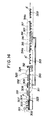
- a continuous elongate ceramic article manufacturing system is constituted of machines arranged in either of two kinds of sequential arrangement, namely, a sequential arrangement of a vacuum extruder or an ordinary extruder (hereinafter referred to simply as "extruder") 2, a drying machine 3, a cutting machine 4a and a firing furnace 5a, or a sequential arrangement of the extruder 2, the drying machine 3, a firing furnace 5b and a cutting machine 4b.
- extruder an ordinary extruder
- a perforating machine 7, a spreading machine 8, a rolling machine 9, edge cutting machine l0, a heater ll, a straightening machine l2, a glazing machine l3a or l3b, a conveying machine l4a or l4b, a conveying and delivering machine l5a or l5b are incorporated properly to the former or the latter basic sequential arrangement.
- clay l0l corresponding to the material l in Fig. l is prepared by mixing and kneading several kinds of materials and chamotte by a kneading machine (not shown) and is supplied to an extruder l03 corresponding to the extruder 2 in Fig. l by a belt conveyor l02.
- the extruder l03 extrudes the clay l0l through a nozzle l04 and a lattice core l05 in a continuous strip having a shape, for example, as illustrated in Fig. 3(a) or 3(b). Since the clay l0l is a mixture mostly of natural substances, the composition thereof is specific to the place of origin of the components.
- the clay l0l having desired properties is prepared by mixing various clays complementing each other.
- the clay l0l is prepared, for example, by kneading water and a mixture of crushed materials such as pottery stone, feldspar, kaolinite, halloysite, pyrophillite, quartz, Kibushi clay, Gairome clay and, when necessary, alumina and zirconia.
- the clay l0l is removed of iron matters by a magnet.
- the lattice core l05 is a hollow member having a longitudinal section corresponding to the shape, for example, a square shape, of the hollow B of a continuous strip A to be extruded.
- a pipe l06 having one end connected to a variable capacity pump l07 is connected at the other end to the rear end of the core l05 to reduce drying time by a great extent through the forced ventilation of the hollows B of the continuous strip A.
- dry hot air 20 to l60°C in temperature and 0 to 30% in humidity is circulated through the hollows B so that the continuous strip A is dried uniformly.
- An infrared-ray heater l08 corresponding to the heater ll of Fig. l dries the continuous strip A throughout, namely, from the central portion to the surface of the continuous strip A by far infrared rays, within a short time.
- the infrared-ray heater l08 reduces the moisture content of the continuous strip A, for example, from a value in the range of l5 to 25% to a value in the range of l0 to 5% to enhance the shape retentivity of the continuous strip A.
- a drying machine l09 corresponding to the drying machine 3 of Fig. l heats the continuous strip A at a temperature in the range of 90 to 400°C to further reduce the water content of the continuous strip A, for example, to 5 to 0%.
- Hot air heated by the waste heat of a firing furnace ll2 corresponding to the firing furnace 5b of Fig. l is blown through a pipe ll0 against the continuous strip A and is stirred by a fan lll as shown in Fig. 6 to heat the interior of the drying machine l09 uniformly and to promote the evaporation of water.
- Temperature distribution in the firing furnace ll2 is represented by an upward convex curve with respect to the direction from the entrance ll2a to the exit ll2b.
- the interior of the firing furnace ll2 is divided substantially into a preheating zone ll3 of l50 to 700°C, a firing zone ll4 of 800 to l350°C, and a cooling zone ll5 of 600 to l00°C.
- the respective temperatures of these zones are determined selectively so as to meet firing conditions specific to the type and composition of the clay l0l, and these zones ll3, ll4 and ll5 are not necessarily demarcated distinctly in respect of temperature; these zones ll3, ll4 and ll5 are substantial divisions in a continuous firing process.
- Kerosene or an inflammable gas, such as LPG is burnt in the firing furnace ll2 to fire the continuous strip A.
- Burners (not shown) are disposed in the firing furnace ll2 in an appropriate arrangement so that the preheating zone ll3, the firing zone ll4 and the cooling zone ll5 are substantially demarcated in the firing furnace ll2.
- the continuous strip A is conveyed by a conveying device employing a mesh wire belt, metallic rollers or ceramic rollers.
- high-alumina ceramic rollers ll8 each is mounted on a pair of parallel metallic rollers ll6 and ll7 as shown in Fig. 7 for conveying the continuous strip A to prevent heat being transmitted through the conveying device to the driving unit.
- a conveying machine ll9 comprises, for example, driving wheels l20, driven wheels l2l, a mesh wire belt l22 extended between the driving wheels l20 and the driven wheels l2l, and a plurality of free supporting rollers l23 arranged between the driving wheels l20 and the driven wheels l2l.
- the conveying machine ll9 is extended through the heater l08 and the drying machine l09.
- the linear path of the continuous strip A is covered with a heat insulating cover l24.
- the walls of the firing zone ll4 of the firing furnace ll2 are formed of refractory bricks or ceramic fibers.
- the continuous strip A is passed continuously and linearly through the firing zone ll4.
- the firing furnace ll2 is provided with ventilating dampers in an appropriate arrangement.
- a moving cutter l25 corresponding to the cutting machine 4b of Fig. l cuts the continuous strip A into elongate ceramic plates A ⁇ of a fixed length.
- a conveying and delivering machine l26 corresponding to the conveying and delivering machine l5b of Fig. l conveys the elongate ceramic plates A ⁇ at a speed higher than the delivery speed of the firing furnace ll2 to separate the elongate ceramic plates A ⁇ from the continuous strip A.
- Free supporting rollers or conveyor belts are disposed between the heater l08 and the drying machine l09 and between the drying machine l09 and the firing furnace ll2 so that the continuous strip A is conveyed normally without drooping between the heater l08 and the drying machine l09 and between the drying machine l09 and the firing furnace ll2.
- the material clay l0l is prepared by kneading a mixture of 6l.5% wt natural clay, 20% wt chamotte, 0.5% wt water reducing agent ("SELFLOW", Daiichi Kogyo Seiyaku K.K.) and l8% wt water by a clay kneader ("Type MP-l00", Miyazaki Tekko K.K.).
- the extrusion capacity of the extruder (“Type MV-FM-A-l", Miyazaki Tekko K.K.) is l00 to l50 l/hr.
- the pump l07 is an exhaust pump driven by a 2 HP motor.
- the heater l08 has twenty sets of far infrared-ray panel heaters of 4 to 400 ⁇ wavelength arranged in a space of l0 m in length.
- the heater l08 is capable of causing moisture contained in the continuous strip A to diffuse from the surface for rapid drying, and capable of reducing the water content of the continuous strip A to l0%.
- the drying machine l09 raises the temperature of the continuous strip A up to 200 to 300°C while the continuous strip A is conveyed for about l0 to 30 m. In this embodiment, the capacity of the drying machine l09 is 300°C ⁇ l0 m.
- the continuous strip A is heated from l50 to 800°C in the 8 m long preheating zone ll3, and from 800 to l300°C in the 5 m long firing zone ll4, and then is cooled from l300 to l00°C in the 8 m long cooling zone ll5.
- the traveling speed of the continuous strip A is 0.l to 20 m/min.
- the mesh wire belt l22 is extended through the heater l08 and the drying machine l09.
- Stainless steel rollers are provided in the preheating zone ll3 and the cooling zone ll5 as conveying means, while alumina rollers are provided in the firing zone ll4 as conveying means.
- the path along which the continuous strip A is conveyed is horizontal.
- the moving speed of the continuous strip A corresponds to the extruding speed.
- the material clay l0l is supplied by the belt conveyor l02 to the vacuum extruder l03.
- the continuous strip A having a cross section as illustrated in Fig. 3(a) extruded by the vacuum extruder l03 is conveyed by the mesh wire belt l22 into the heater l08.
- the heater l08 reduces the water content of the continuous strip A to about l0%, and then the drying machine l09 reduces the water content of the continuous strip to 5 to 0%.
- the continuous strip A is preheated, fired and cooled in the firing furnace ll2 to form a continuous ceramic strip.
- the continuous ceramic strip is cut into longate ceramic plates A ⁇ having a fixed length, for example, 2424 mm, 3030 mm or 3636 mm by the moving cutter l25.
- the continuous elongate ceramic article manufacturing system in the first embodiment, according to the present invention described hereinbefore is capable of producing a continuous strip of clay in a short time at a high speed by extruding the clay in a continuous strip, reducing the water content of the continuous strip, drying the continuous strip, firing the continuous strip and cooling the continuous strip through processes arranged along a straight processing line. Since an infrared-ray heater and hot air heated by waste heat are used and the hollows B of the continuous strip A are ventilated to reduce the water content of the continuous strip A, the water content of the continuous strip A can be reduced smoothly in a short time at a low cost. Thus, the continuous elongate ceramic article manufacturing system of the present invention enables highly efficient mass-production of such a continuous strip.
- the fired continuous ceramic strip may be cut into elongate ceramic plates having an optional length. Therefore, the distortion of the elongate ceramic plates due to shrinkage resulting from firing, particularly, dimensional errors due to longitudinal shrinkage, which has been the defect of ceramics, can be eliminated.
- the second embodiment is substantially the same as the first embodiment except that a perforating machine l30 corresponding to the perforating machine 7 of Fig. l and a glazing machine l3l corresponding to the glazing machine l3b of Fig. l are incorporated additionally to the system.
- the perforating machine l30 is disposed next to the vacuum extruder l03.
- the perforating machine l30 has a perforating roller l32 provided on the circumference thereof with spikes l33 arranged at appropriate axial and circumferential intervals.
- the perforating roller l32 is rotated at a rotating speed corresponding to the extruding speed of the vacuum extruder l03 to form ventilating holes l34 only in the backside of a continuous strip A extruded by the vacuum extruder l03, as illustrated in Fig. 3(c).
- the ventilating holes l34 promote reducing the drying time in circulating air through the hollows B of the continuous strip A.
- the size of the spikes l33 of the perforating roller l32 is, for example, 2 mm in diameter and 5 mm in height.
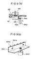
- the perforating machine l30 may employ a perforating plate l04l having perforating teeth l04lb longitudinally arranged at intervals as illustrated in Figs. 9(a) and 9(b).
- the perforating plate l04l is driven for vertical reciprocatory motion in front of the front end l04a of the nozzle l04 by vertically reciprocatory driving means l042.
- Slots l04la are formed in the perforating plate l04l to allow the vertical and lateral movement of the perforating plate l04l relative to the nozzle l04.
- the glazing machine l3l comprises a glaze applicator l36, such as a spray gun or a flow coater (a spray gun is shown in Fig. l0) for applying a glaze l35, a belt conveyor l37, and a glaze pan l38.
- the belt conveyor l37 has a plurality of V-belts or the like extended between wheels l39 as illustrated in Fig. l0.
- the V-belts are those with knife edge.
- the second embodiment additionally incorporating the perforating machine l30 and the glazing machine l3l is capable of producing a continuous strip along a straight processing line, in a short time and at a high speed by extruding the clay, reducing the water content of the continuous strip by utilizing the hollows and ventilating holes of the same, applying the glaze, drying the glazed continuous strip, firing the glazed continuous strip, and then cooling the fired continuous strip. Since an infrared-ray heater and hot air heated by waste heat are used and air is circulated through the hollows and ventilating holes of the continuous strip in reducing the water content of the continuous strip, the water content is reduced smoothly in a short time at a low cost. Furthermore, the continuous elongate ceramic article manufacturing system enables highly efficient mass-production of such a continuous strip. Still further, the glazing of the continuous strip can easily be accomplished during the continuous manufacturing process when necessary.
- the third embodiment has a conveying machine l40 employing free supporting rollers, a mesh wire belt, a cloth belt or a steel wire belt between the vacuum extruder l03 and the drying machine l09 instead of the heater l08. Since a continuous strip A as extruded is conveyed by the conveying machine l40, the conveying machine l40 serves as an observation zone for observing the condition of extrusion.
- the conveying machine l40 may employ embossing rollers R to serve as an embossing process or may employ free supporting rollers to serve as a straightening process.
- an infrared-ray heater may be employed instead of the drying machine l09 utilizing the waste heat of the firing furnace ll2.
- a far infrared-ray heater is particularly suitable for drying the surface and the central portion of the continuous strip A simultaneously in a short time because the heat rays are highly penetrative when radiated on quartz and kaolin of the clay l0l.
- Clay 20l a mixture of several kinds of clays, is extruded continuously in a continuous strip A, for example, through a nozzle 203, by an extruder 202 corresponding to the extruder 2 of Fig. l.
- the continuous strip A has a cross section as shown in Fig. l3(a), l3(b), l3(c) or l3(d).
- the continuous strip A is fed continuously to the next process.
- the clay 202 is prepared, for example, by crushing materials such as pottery stone, fedlspar, kaolinite, halloysite, sericite, kibushi clay, Gairome clay, and by adding materials such alumina, zirconia, talc, magnesium carbonate, calcium carbonate, and by mixing a mixture of the crushed materials, water, when necessary, 0.5 to 80% wt or less materials such as chamotte, inorganic fibers (asbestos fibers, glass fibers or calcium silicate fibers), pulp, and 0.0l to l% wt water reducing agent such as an inorganic deflocculating agent (sodium silicate, sodium phosphate, sodium aluminate or lithium carbonate) and/or organic deflocculating agent (duethyl amine, ethylamine, naphthlene, sulfonic acid, polyvinyl alcohol, carboxymethyl cellulose) by a rough kneading machine.
- the nozzle 203 is such a nozzle that will withstand a force that acts thereon in extruding the clay 20l and, when necessary, equipped with a lattice core as shown in Fig. 5. It is possible to connect a device for supplying a fluid heated to a high temperature into and for discharging moisture from the hollows of an extruded continuous strip A to the lattice core in order to dry the continuous strip A uniformly and quickly.
- a straightening machine 204 has a plurality of parallel free conveyor rollers having smooth circumference extended across the straight conveying path horizontally extending from the nozzle l03 one after another.
- the free conveyor rollers 204a apply frictional resistance against the transverse movement of the continuous strip A to guide the same along the straight conveying path.
- the synergistic effect of the guiding function of the free conveyor rollers 204a and the conveying function of the conveying machine 5 further enhances the straightening function of the straightening machine 204.
- the conveying machine 205 has conveyor rollers, a cloth belt or the like which is driven at a surface speed higher than the moving speed of the continuous strip A, for example, by 0.l to 5%, to convey the continuous strip A under tension.
- the continuous strip A is conveyed along the straight conveying path and is prevented from distortion, by the synergistic action of the frictional resistance of the free conveying rollers 204a and the pulling action of the conveying machine 205.
- the straightening machine 204 and the conveying machine 205 serve as an observation zone for facilitating the observation of the condition of extrusion as well as means for conveying the continuous strip A as extruded from the nozzle 203 to the next process.
- a drying machine 206 reduces the water content of the continuous strip A from l5 to 25% to approximately l% in a short time in the range of several minutes to several hours.
- the drying machine 206 employs an infrared-ray heater, a far infrared-ray heater, a microwave heater or hot air, or a combination of one or more of those heating means as the heat source 207.
- An infrared-ray heater and a far infrared-ray heater in particular, are effective for drying the surface and the central portion of the continuous strip A simultaneously in a short time utilizing the synergistic effect of far infrared rays radiated from quartz and fedlspar of the clay radiated by infrared rays.
- a conveying mechanism 208 comprises heat-resistant conveyor rollers or a heat-resistant mesh wire belt (not shown) arranged in the drying zone of the drying machine 206 to convey the continuous strip A along the conveying path.
- a drying zone for reducing the water content of the continuous strip A to approximately 6 to 8% are provided free rollers 208a, while in the other zone subsequent to the former zone are provided driving rollers 208b rotating at a rotating speed corresponding to the moving speed of the continuous strip A.
- a moving cutter 209 employing rotary cutting blade means, laser beam cutting means, electric discharge cutting means or wire-cut cutting means cuts the continuous strip A into pieces having an optional length, for example, a length in the range of 300 to 4000 mm.
- the moving cutter 209 cuts the continuous strip A moving at the same speed as the moving speed of the continuous strip A.
- the moving speed of the continuous strip A corresponds to the extrusion speed of the vacuum extruder 20l, while the moving speed of the continuous strip A during drying varies with shrinkage.
- a delivering mechanism 2l0 delivers the cut pieces C having a fixed length to the next process by means of driving rollers or a conveyor belt at a speed higher than the extruding speed of the extruder 202.
- a firing furnace namely, a roller hearth kiln or a tunnel firing furnace.
- the interior of the firing furnace 2ll is divided substantially into a preheating zone 2l2, a firing zone 2l3 and a cooling zone 2l4.
- Temperature distribution in the firing furnace is represented by an upward convex curve with respect to the direction from the entrance 2lla to the exit 2llb.
- the straightening machine is interposed between the extruder and the conveying mechanism, the continuous strip as extruded is conveyed to the drying machine along a straight conveying path without being distorted, and thereby the distortion of the product is reduced remarkably as compared with products produced by the conventional ceramic article manufacturing system.
- clay 30l is prepared by kneading several materials and, if necessary, chamotte by a kneading machine (not shown).
- the clay 30l is supplied by a belt conveyor 302 to an extruder 303.
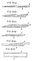
- the extruder 303 extrudes the clay 30l through a nozzle 304 provided with a lattice core 305 (Fig. 5) in a continuous strip A having hollows B and a cross section as shown in one of Figs. l5(a) to l5(f).
- the lattice 305a of the lattice core 305 are hollow rods having sections corresponding to the sections of the hollows B formed in the continuous strip A.
- a pipe 306 connected at one end to a pump 307 is connected at the other end to the core 305 for the forced supply of hot air, warm air of dry air into the hollows B of the continuous strip A or for the forced ventilation of the hollows B of the continuous strip A in order to reduce the continuous strip drying time effectively.
- a drying machine 308 comprises an infrared-ray or a microwave heat source 309 and a conveying mechanism 3l0.
- the continuous strip A is dried uniformly from the central portion to the surface thereof in a short time by the synergistic effect of the forced ventilation of the hollows B of the continuous strip A for making the water contained in the continuous strip A evaporate from the surfaces of the hollows B, and the heating effect of the heat source 309.
- the drying machine reduces the water content of the continuous strip A, for example, from l5 to 25% down to 0 to 5%, so that the shape retentivity of the continuous strip A is enhanced and the continuous strip A is prepared for firing.
- the drying machine 308 is equipped with far infrared-ray heaters or microwave heaters, alternate arrangement of far infrared-ray heaters and microwave heaters, or heaters disposed in the initial drying zone and heaters disposed in the final drying zone.
- the drying machine 308 heats the continuous strip A up to 800 to 500°C according to a heating curve so that the continuous strip A will not crack.
- the conveying mechanism 3l0 comprises free rollers, driven rollers, conveyor belt (not shown), mesh wire belt (not shown), or a combination of these conveying means.
- the drying machine 308 may be provided with a heating device 311 which utilizes the waste heat of a firing furnace 314 which will be described hereinafter.
- a moving cutter 312 corresponding to the cutter 4a of Fig. 1, employing rotary blade cutting means, laser cutting means, hydraulic cutting means or electric discharge cutting means cuts the dried continuous strip A into elongate dry plates A" having a fixed length.
- a conveying mechanism 313 corresponding to the conveying machine 14a of Fig. 1 conveys the dry plates A" dut by the moving cutter 312 to the firing furnace 314.
- the interior of the firing furnace 314 is divided substantially into a preheating zone 315, a firing zone 316 and a cooling zone 317. Temperature distribution in the firing furnace is represented by an upward convex curve with respect to the direction from the entrance 314a to the exit 314b.
- the approximate temperature ranges in the preheating zone 315, the firing zone 316 and the cooling zone 317 are 150 to 700°C, 800 to 1350°C and 600 to 100°C, respectively.
- the respective set temperatures of the preheating zone 315, the firing zone 316 and the cooling zone 317 are dependent on the type and composition of the clay 30l, and these zones 3l5, 3l6 and 3l7 are not necessarily demarcated distinctly in respect of temperature and are substantial divisions in a continuous firing process.
- Kerosene or an inflammable gas, such as LPG is burnt in the firing furnace 3l4 to fire the dry plates A ⁇ .
- Burners (not shown) are disposed in an appropriate arrangement so that the preheating zone 3l5, the firing zone 3l6 and the cooling zone 3l7 are substantially demarcated in the firing furnace 3l4.
- the dry plates A ⁇ are conveyed by a conveying device employing a mesh wire belt, metallic rollers or ceramic rollers.
- high-alumina rollers 320 i.e., ceramic rollers, each is mounted on a pair of parallel metallic rollers 3l8 and 3l9 as shown in Fig.
- the linear path of the dry plates A ⁇ is covered with a heat insulating cover 32l.
- the walls of the firing zone 3l5 of the firing furnace 3l4 are formed of refractory bricks or ceramic fibers.
- the dry plates A ⁇ are conveyed continuously and linearly through the firing zone 3l5.
- the firing furnace 3l4 is provided with exhaust dampers (not shown) in an appropriate arrangement.
- Conveying devices 322 and 323 each comprises a plurality of rollers, a conveyor belt, or a combination of rollers and a conveyor belt.
- the conveying device 322 conveys elongate ceramic plates A ⁇ produced by firing the dry plates A ⁇ , at a speed higher than the delivering speed of the firing furnace 3l4 so that the elongate ceramic plates A ⁇ will not collide with each other.
- the conveying device 323 is provided only when necessary.
- the conveying mechanism 3l0 employs free rollers
- the conveying device 323 conveys the continuous strip A extruded from the nozzle 304 at a speed corresponding to or somewhat higher than the extruding speed to convey the continuous strip A under tension to the conveying mechanism 3l0.
- the conveying mechanism 3l0 employing the free rollers straightens the continuous strip A.
- the clay 30l is prepared by kneading a mixture of 6l.5% wt natual clay, 20% wt chamotte, 0.3% wt water reducing agent ("SELFLOW", Daiichi Kogyo Seiyaku K.K.) and l8% wt water by a clay kneader ("Type MP-l00", Miyazaki Tekko K.K.).
- the extruding capacity of the extruder (“Type MV-FM-A-l", Miyazaki Tekko K.K.) is l00 to l50 l/hr.
- the pump 307 is driven by a 5 HP motor for sucking or exhausting air.
- the drying machine 308 is provided with twenty sets of far infrared-ray panel heaters of 4 to 400 ⁇ wavelength arranged in a space of l0 m in length.
- the drying machine 308 reduces the water content of the continuous strip A down to 0 to 2% in about ten minutes by heating the continuous strip A by the far infrared-ray panel heaters and warm air of about 30°C causing the surface evaporation by radiation and internal diffusion of moisture by warm air circulation through pipe 306. Then, the continuous strip A thus dried is cut by the moving cutter 3l2 into the dry plates A ⁇ of 3 m in length.
- the dry plates A ⁇ are conveyed continuously by the conveying mechanism 3l3 to the firing furnace 3l4.
- the firing furnace 3l4 is of the roller hearth kiln type.
- the dry plates A ⁇ are preheated, fired and cooled as they are conveyed along the roller hearth from the entrance 3l4a to the exit 3l4b of the firing furnace 3l4 to produce elongate ceramic plates A ⁇ .
- the fifth embodiment is capable of continuously manufacturing elongate ceramic plates at a high production rate, at a high yield rate and at a low cost through the clay extruding process, the rapid drying process and the firing and cooling process sequentially arranged along a straight line.
- the water content of the continuous strip is reduced smoothly in a short time at a low cost without distorting and cracking the continuous strip by the synergistic effect of infrared rays, hot air (surface evaporation) heated by the waste heat of the firing furnace, and ventilation of the hollows of the continuous strip (internal diffusion).
- the length of the drying process of the fifth embodiment is approximately l/l60 that of the conventional drying process, which reduces the floor space necessary for installing a continuous elongate ceramic article manufacturing system.
- the continuous strip A is cut into the dry plate A ⁇ by the moving cutter 3l2 disposed one to two meters apart from the exit of the drying machine 3l2.
- a moving cutter 324 is disposed contiguously to the exit of the drying machine 308 as indicated by imaginary lines in Fig. l4, to cut the continuous strip A at the exit of the drying machine 308.
- the exit 325 of the drying machine 308 is extended by a length sufficient to cover the continuous strip A to a position immediately before a continuous strip cutting position. If the moving cutter 324 is disposed apart from the exit of the drying machine 308, the continuous strip A heated in the drying machine 308 is cooled while the same travels through the distance between the exit of the drying machine 308 and the moving cutter 324, and thereby the steam contained in the hollows B of the continuous strip A is caused to condense, which, sometimes, distorts or cracks the cut end of the continuous strip A.
- the improvements in the sixth embodiment include disposing the moving cutter 324 contiguously to the exit of the drying machine 308 and extending the exit portion 325 of the drying machine 308 close to the moving cutter 324 so that the continuous strip A will not be neither distorted not cracked.
- the seventh embodiment includes a glazing machine 326 and a drying heater 327 interposed between the moving cutter 3l2 and the firing furnace 3l4 of the fifth embodiment, as shown in Fig. l6.
- the parts and mechanisms of the seventh embodiment like or corresponding to those of the fifth embodiment are designated by like reference characters and the description thereof will be omitted to avoid duplication.
- the glazing machine 326 corresponding to the glazing machine l3a of Fig. l has one or a plurality of spray coating units, curtain flow coating units, screen printing unit or roller coating units for applying a glaze 329 to the decorative surface of the dry plate A ⁇ .
- the glaze 329 is of a known or a new composition. The color, pattern and thickness over the surface of the dry plate A ⁇ of the glaze 329 are dependent on the purpose of the ceramic plate A ⁇ .
- a drying heater 327 evaporates and volatilizes water of the glaze 329 to some extent at approximately 50 to 450°C in one to five minutes. The drying heater 327 may be omitted when the firing furnace 3l4 has a long preheating zone 3l5 of low temperature.
- the seventh embodiment has, in addition to the advantages of the sixth embodiment, an advantage that elongate ceramic plates having glazed surface are produced through a continuous process.
- the eighth embodiment is a modification of the fifth embodiment.
- the lattice core 305 shown in Figs. 5(a) and 5(b) combined with the nozzle 304 of the fifth embodiment has a pipe 306 for supplying or exhausting air attached to the inlet or outlet of the lattice core 305.
- a pipe 330 for circulating hot air through the hollows of the continuous strip A is attached to one side of the lattice core 305 or to the lattice 305a.
- drying machine 308 of the fifth embodiment employs infrared-ray heaters and microwave heaters as the heat source
- drying machine 308 of the eighth embodiment employs a sequential arrangement of a microwave heater 33l and infrared-ray heaters 332.
- the drying machine 308 of the eighth embodiment comprizes a short-period heating unit including a microwave heater 33l and far infrared-ray heaters 332 disposed after the microwave heater 33l, and a conveying mechanism 3l0.
- This arrangement of the heating unit is more effective for drying the continuous strip A uniformly from the central portion to the surface of the same in a short time by the synergistic effect of the evaporation from the inner surfaces caused by air circulation through the hollows B of the continuous strip A and the heating effect of the microwave heater 33l and the far infrared-ray heaters 332.
- the water contained in the central portion of the continuous strip A is caused to diffuse toward the surface by the microwave heater 33l and some part (6 to l0%) of the water is evaporated in a short time in the initial drying stage, and then the rest of the water contained in the continuous strip A is evaporated to reduce the water content down to 0 to 5% by the synergistic effect of the slow-penetrating heat of the far infrared-ray heaters 332 and the air circulated through the hollows B of the continuous strip A by the core 305 through the lattice 305a.
- the interior of the drying machine 308 is substantially divided into a first drying a one and a second drying zone, and the temperature distribution in the drying zones is determined in accordance with an appropriate heating curve varying in temperature in the range of 200 to 500°C to prevent distorting and cracking the continuous strip A.
- Two or more heating units each including the microwave heater 33l and the infrared-ray heaters 332 arranged in this order may be provided to enhance the drying efficiency of the drying machine 308.
- the ninth embodiment is designed to dry a continuous strip A having hollows B in a greatly reduced drying time in the range of five to thirty minutes without distorting and cracking the continuous strip A through balanced surface evaporation and internal diffusion of water contained in the continuous strip by circulating air, hot air, dry air, warm air or steam through the hollows B through the lattice 405a of a lattice core 405 for forming the hollows B in the continuous strip A, combined with the nozzle of an extruder 403, to promote evaporation of water from the inner surfaces of the continuous strip A, by externally heating the continuous strip A in a drying machine 409 by hot air, far infrared rays, microwaves or a combination of these heating means for rapid drying operation, and by connecting a pipe 406 having one end connected to a pump 407 to the core 405 in parallel to the direction of movement of the continuous strip A extruded by the extruder 403 to circulate air, hot air, dry air, warm air or steam efficiently through the hollows B of the continuous
- the nozzle 404 of the extruder 403 is substantially of an L-shape.
- the nozzle 404 is such a nozzle that withstands a force that works thereon in extruding clay 40l.
- the lattice core 405 is incorporated into the nozzle 404.
- the lattice core 405 has a plurality of lattices 405a having a tubular shape. Air, hot air, cool air, dry air or steam is supplied into or is exhausted from the hollows B of the continuous strip A for forced ventilation of the hollows B.
- the lattice core 405 is connected to the pump 407 by the pipe 406.
- the pipe 406 and the lattice core 405 are connected linearly, and the lattice core 405 is mounted on the extruder 403 with the pipe 406 in parallel to the direction of movement of the continuous strip A, so that undue resistance against the flow of the clay 40l is eliminated, extrusion of the continuous strip A in an irregular density distribution is obviated and air can be circulated efficiently through the hollows B of the continuous strip A and thereby evaporation of water through the hollows B and the internal diffusion of water are promoted and rapid drying is achieved.
- a positive conveying machine 408 comprises rollers, belts, mesh wire belts or a combination of these conveying means.
- the conveying machine 408 is operated positively at a conveying speed corresponding to or slightly higher than the moving speed of the continuous strip A extruded by the extruder 403.
- the conveying machine 408 extends partly (Fig. l7) or entirely in a drying machine 409.
- the tenth embodiment incorporates further improvements in the drying machine 308 of the eighth embodiment comprising a sequential arrangement of the microwave heater 33l and the far infrared-ray heater 332.
- a drying machine employing microwave heaters and far infrared-ray heaters such as the drying machine 308 shown in Fig. l4, has problems. That is, the microwave heater is unable to heat the continuous strip A up to a temperature on the order of l30°C, rapid heating causes the continuous strip A to blow, the microwave heater is more expensive than the far infrared-ray heater, and the operating cost of the microwave heater is higher than the far infrared-ray heater.
- the far infrared-ray heater needs more time than the microwave heater in raising the temperature of the interior of the continuous strip A, the far infrared-ray heater is far more advantageous in respect of cost effective than the microwave heater in raising the temperature of the interior of the continuous strip A.
- such a drying machine has several matters to be improved in preventing the frosting of a large amount of steam produced in drying the continuous strip A, and in drying and conveying the continuous strip A, such as the distortion of the continuous strip A by the frictional resistance of the conveyor belt against the movement of the continuous strip A, and irregular heating of the continuous strip A by the microwave heater.
- a microwave heating machine 503 capable of dielectric heating is disposed next to a vacuum extruder 50l, and a far infrared-ray heating machine 5l3 for raising the temperature of the continuous strip A is disposed after the microwave heating machine 503.
- the microwave heating machine 503 incorporates several improvements.
- the microwave heating machine 503 of a continuous oven system heats the interior of the continuous strip A within several seconds to several minutes by dielectric heating effect to evaporate the water contained in the continuous strip A.
- the microwave heating machine 503 reduces the water content by 5 to l0% among l5 to 25% water content of the continuous strip A.
- the continuous strip A of this kind diminishes in volume until the water content is reduced to 5 to 8% and stops diminishing in volume thereafter.
- the microwave heating machine 503 comprises: a waveguide 504 which propagates microwaves transmitted by a microwave oscillator (not shown) to desired zones in the microwave heating machine 503; reflectors 505 for reflecting the microwaves; fans 506 for stirring the reflected microwaves; a conveying mechanism 507 comprising accepting rollers such as free rollers or a driven conveyor belt, preferably, free rollers capable of reflecting microwaves on the backside of the continuous strip A, for conveying the continuous strip A at a conveying speed corresponding to the extruding speed; an entrance 508; an exit 509; an enclosure 5l2 enclosing the heating chamber 5l0 so that microwaves will not leak outside; and a conduit 5ll opening into the heating chamber 5l0 to supply air into the heating chamber 5l0.
- the entrance 508 and the exit 509 have a construction and size which will not allow microwaves to leak from the heating chamber 5l0.
- the length of the heating chamber 5l0 is in the range of l to 5 m.
- the conveying mechanism 507 employs free conveyor rollers to allow the continuous strip A to shrink by about l0%.
- the microwave heating machine is employed to dry the continuous strip A uniformly, efficiently and rapidly. Since the continuous strip A is plastic, the continuous strip A is liable to be distorted or broken while the same is being conveyed. Accordingly, the microwave heating machine must be constituted so as to heat the continuous strip A without cracking or breaking the continuous strip A and without generating sparks. In the heating chamber, the continuous strip A may be irradiated directly by microwaves radiated from the waveguide instead of the microwaves reflected by the reflectors.
- the microwave heating machine is designed so as to suppress the thermal expansion of the continuous strip A resulting from the heat generated within the continuous strip A by the heating effect of microwaves and to prevent the adverse overheat and distortion of the continuous strip A by supplying and circulating air along both the external surface (exposed surface) and the internal surfaces defining the hollows of the continuous strip A to remove steam from the continuous strip A and to discharge a large amount of steam from the heating chamber.
- the far infrared-ray heating machine 5l3 heats the continuous strip A up to l30°C or above to reduce the water content of the continuous strip A down to 5 to 0%.
- the far infrared-ray heating machine 5l3 comprises: a conveying mechanism 5l4 employing free rollers or a conveyor belt; far infrared-ray heaters 5l5; and a heat insulating enclosure 5l6.
- the length of the heating zone of the far infrared-ray heating machine 5l3 is in the range of 2 to l0 m. Naturally, the length of the heating zone is dependent on the thickness, width and length of the half-dried continuous strip A and the conveying speed.
- the clay is prepared by kneading a mixture of 6l.5% wt natural clay, l8% wt chamotte, 0.3% wt water reducing agent ("SELFLOW", Daiichi Kogyo Seiyaku K.K.), and 20% wt water by a clay kneading machine ("Type MP-l00", Miyazaki Tekko K.K.).
- the extrusion capacity of the extruder 50l (“Type VM-FM-A-l", Miyazaki Tekko K.K.) is l00 to l50 l/hr.
- the conveying machine 502 has free rollers and a driven conveyor belt arranged in that order.
- the microwave heating machine 503 has a capacity of 5 KW output and uses 2450 MHz microwaves.
- the length of the heating chamber of the microwave heating machine 503 is 3 m.
- air is supplied at a high rate through the conduit 5ll attached to the enclosure into the heating chamber 5l0 to prevent the steam generated by heating the continuous strip A from condensing over the inner surface of the enclosure 5l2 and over the surface of the continuous strip A by discharging the steam through the entrance 508 and the exit 509 to reduce the partial pressure of the steam in the heating chamber 5l0.
- the conveying mechanism 507 employs free rollers formed of fluororesin (Teflon ® ).
- the far infrared-ray heating machine 5l3 comprises a plurality of far infrared-ray heaters arranged in the heating zone having a length in the range of 3 to l0 m.
- the capacity of the far infrared-ray heating machine 5l3 is, for example, 20 KW.
- the microwave heating machine 503 reduces the water content of the continuous strip A from l8% to l2%, and then the far infrared-ray heating machine 5l3 reduces the water content substantially to 0%.
- the extruding speed of the extruder 50l is in the range of l00 to 2000 mm/min. In an experimental operation, the extruding speed was 400 mm/min.
- the continuous strip A is moved along a horizontal path, and is fed to the microwave heating machine 503 by the driven conveyor belt operating at a conveying speed corresponding to the extruding speed.
- the free rollers of the conveying mechanism 507 of the microwave heating machine 503 allow the volumetric shrinkage of the continuous strip A attributable to the reduction of the water content.
- the clay supplied to the extruder 50l is extruded in the continuous strip A having a predetermined cross-sectional shape.
- the continuous strip A is supplied by a conveying device 502 into the microwave heating machine 503. While the continuous strip A is conveyed through the microwave heating machine 503, the water content thereof is reduced to l2% in five minutes.
- the continuous strip A is conveyed to the far infrared-ray heating machine 5l3, where the water content of the continuous strip A is reduced to l% or less in approximately ten minutes.
- the continuous strip A is dried in about l5 to 20 min after the same has been extruded by the extruder 50l.
- the dried continuous strip A is cut by a moving cutter 5l7 into pieces having a predetermined length, and then the pieces are supplied to a glazing process (not shown) or a firing process (not shown).
- the moving cutter may be disposed at a position indicated by alternate long and short dash lines in Fig. 20, and hot air or warm air may be circulated through the microwave heating machine 503 and the far infrared-ray heating machine 5l3 by air supply means (only air supply means for the far infrared-ray heating machine 5l3 is indicated by imaginary lines in Fig. 20) to further reduce the drying time.
- the tenth embodiment of the present invention is capable of drying extruded pieces of clay and an extruded continuous strip of clay having a water content of l5 to 25% by two heating processes in a drying time l/l00 to l/300 the drying time of the conventional system without cracking, blowing, twisting and warping the extruded pieces and the extruded continuous strip.
- the extruded pieces and the extruded continuous strip shrink in volume by about l0% during the drying process, the conveying mechanism allows the free shrinkage of the extruded pieces and the continuous strip.
- the eleventh embodiment is an improvement of the tenth embodiment.
- air is supplied at a high rate into the heating chamber 5l0 of the microwave heating machine 503 to discharge a large amount of steam generated by heating the continuous strip from the heating chamber 5l0 to prevent the steam from condensing over the inner surface of the heating chamber 5l0 and over the surface of the continuous strip A so that the continuous strip A can be dried in ten to one hour without being cracked, warped, twisted and blown as the continuous strip A is advanced continuously through the heating chamber 5l0.
- the microwave heating machine 503 of the eleventh embodiment can be formed in a compact construction.
- a conduit 5l8 opening into the heating chamber 5l0 is connected to an air circulating device 5l9, such as an air compressor or a ring blower.
- the air circulating device 5l9 When air is supplied at a high rate into the heating chamber 5l0 by the air circulating device 5l9, the air is circulated through and is discharged together with steam prevailing in the heating chamber 5l0 from the heating chamber 5l0 through the entrance 508 and the exit 509. Accordingly, the partial pressure of steam in the heating chamber 5l0 is reduced and thereby further efficient prevention of the condensation of steam over the inner surface of the enclosure 5l2 is achieved.
- an extruder 60l extrudes clay in a continuous strip A having a cross-sectional shape as shown in Fig. l3(a), l3(b), l3(c) or l3(d).
- the extruding speed of the extruder 60l is, for example, in the range of l00 to 2000 mm/min.
- a conveying machine 602 comprises free conveyor rollers 603 and a driven conveyor belt 604 arranged in that order, and conveys the soft continuous strip A continuously to the next process at a conveying speed corresponding to the extruding speed along a path extending on the level of the nozzle of the extruder 60l without distorting the soft continuous strip A.
- the free conveyor rollers 603 convey the continuous strip A as extruded without applying any frictional resistance thereto.
- the driven conveyor belt 604 conveys the continuous strip A positively to the next process at a conveying speed substantially the same as the extruding speed so that the continuous strip A somewhat hardened as the same is conveyed through a distance of half a meter to two meters from the nozzle of the extruder 60l will not be compressed by the cooperative effect of the force of extrusion and the weight of the preceding portion of the continuous strip A.
- a microwave heating machine 605 is of a continuous oven type substantially the same as that of the tenth embodiment.
- the microwave heating machine 605 comprises: a waveguide 606 which propagates microwaves M transmitted by a microwave oscillator (not shown) to desired zones in the microwave heating machine 605; reflectors 607 for reflecting the microwaves M; fans 608 for stirring the reflected microwaves; conveying mechanism 6l0 comprising free rollers 609, for conveying the continuous strip A at a conveying speed corresponding to the extruding speed; a filtering entrance 6ll; a filtering exit 6l2; an air supply openings 6l4 for blowing air into a heating chamber 6l3; and an enclosure 6l5 enclosing the heating chamber 6l3 to prevent microwaves M from leaking from the heating chamber 6l3.
- the twelfth embodiment is featured by the conveying machine 602 comprising the free rollers 603 and the driven conveyor belt 604, which conveys the continuous strip A positively at a conveying speed substantially the same as the extruding speed along a path on the same level as a path line extending between the extruder 60l and the microwave heating machine 605, disposed between the extruder 60l and the microwave heating machine 605 which reduces the water content of the continuous strip A in a short time, the free rollers of the conveying mechanism of the microwave heating machine 605, and the air supply openings 6l4 for supplying air into the heating chamber 6l3.
- the soft continuous strip A having a water content of l5 to 25% is supplied continuously and smoothly without being distorted to the microwave heating machine (primary drying machine), the microwave heating machine 605 absorbs the volumetric shrinkage of the continuous strip A, and the microwave heating machine 605 dries the continuous strip A in a reduced time l/l00 to l/300 the drying time of the conventional drying machine. Since the conveying path extends linearly from the extruder 60l through the microwave heating machine 605, the continuous strip can smoothly be dried to a desired extent.
- the thirteenth embodiment comprises: an extruder 70l; a conveying machine 709 for smoothly conveying a continuous hollow strip A to the next process; a microwave heating machine 7l2 which evaporates about one-third of the water contained in the continuous hollow strip A in a short time in the range of one to thirty minutes; and a far infrared-ray heating machine 726 which reduces the water content of the continuous hollow strip A to l% or below in a short time in the range of one to thirty minutes, arranged in that order.
- Air or dry air is blown into the hollows of the continuous hollow strip A through an opening formed in the core of the nozzle of the extruder 70l to remove the steam stagnating within the hollows while the continuous hollow strip A is being heated so that portions of the continuous hollow strip A surrounding the hollows are heated efficiently, and to prevent the condensation of steam within the hollows so that the continuous hollow strip A is dried uniformly.
- the continuous elongate ceramic article manufacturing system in the twelfth embodiment, according to the present invention is formed in a compact construction, and is capable of continuously manufacturing elongate ceramic articles.
- a nozzle internally provided with a core (not shown) connected by a hose 708 to a pump 707 for supplying air to the core.
- a conveying machine 709 free rollers 7l0, a driven conveyor belt 7ll, a conveying mechanism 7l6, an entrance 7l7, an exit 7l8, a heating chamber 7l9, air supply opening 720, an enclosure 72l, a conveying mechanism 727, far infrared-ray heaters 728, a heat insulating box 729, and a moving cutter 730.
- a waveguide 7l3 propagates microwaves M transmitted by a microwave oscillator (not shown).
- a reflector 7l4 is for reflecting the microwaves M.
- a way of introduction of the microwaves M into the enclosure 72l will be described in detail in a next fourteenth embodiment.
- the air supply opening 720 is connected to the pump 707 by another hose 748.
- the conveying mechanism 7l6 is designed so that the upper surface, side surfaces and lower surface of the continuous hollow strip A are exposed uniformly to the microwaves and air supplied into the heating chamber 7l9 and so that the continuous hollow strip A is allowed to shrink in volume by about l0% when heated.
- the conveying mechanism 7l6 comprises, for example, free rollers 723 each formed of fluororesin (Teflon ® ), fixed shafts 722 rotatably supporting the free rollers 723, respectively, frame members 724 fixedly supporting the fixed shafts 722, and, when necessary, shielding plates 725.
- FIG. 24(a) is divided longitudinally into three separate sections to reduce the resistance of the free roller 722 against the movement of the continuous hollow strip A.
- the free roller 723 ⁇ shown in Fig. 24(b) is formed in a single member.
- slots 724a are formed in each frame member 724 to expose the backside of the continuous hollow strip A to microwaves.
- the shielding plates 725 are effective to prevent the physically possible excessive exposure of the respective upper portions of the side surfaces of the continuous hollow strip A to microwaves for uniform heating of the continuous hollow strip A.
- the fourteenth embodiment incorporates an improved microwave heating machine.
- the improved microwave heating machine comprises: a waveguide 80l which propagates microwaves transmitted by a microwave oscillator (not shown) to desired zones in the microwave heating machine; reflectors 802 which dispersively reflects the microwaves in a heating chamber 803; fans 804 which stirs the reflected microwaves M to distribute the microwaves M uniformly within the heating chamber 803; and a roller conveyor 805 designed so as to expose the continuous strip A uniformly to the microwaves M and air supplied into the heating chamber 803 and to allow the volumetric shrinkage on the order of l0% of the continuous strip A while the same is being dried and to convey the continuous strip A without distorting the same.
- the constitution of the roller conveyor 805 is substantially the same as that shown in Figs. 24(a), 24(b) and 25. That is, the roller conveyor 805 comprises: free rollers 807 formed of fluororesin (Teflon ® ); fixed shafts 806 rotatably supporting the free rollers 807, respectively; supporting frames 808 fixedly supporting the fixed shafts 806; and shielding plates 809. Slots 808a are formed in each supporting frame 808 to expose the backside of the continuous strip A to microwaves. The shielding plates 809 are effective to prevent the excessive exposure of the respective upper portions of the side surfaces of the continuous strip A to microwaves for uniform heating of the continuous strip A.
- Pipes 8l3 for supplying or exhausting air therethrough are attached to the wall of the heating chamber 803. The pipes 8l3 are connected to an air circulating device capable of blowing or sucking air, dry air or warm air, such as an air compressor or a ring blower (not shown).
- the free rollers 807 capable of allowing the free volumetric shrinkage of the continuous strip are employed for conveying the continuous strip, the opposite ends of the free rollers 807 are covered with the shielding plates 809 having a U-shaped cross section to prevent the excessive exposure of the side surfaces of the continuous strip to microwaves, respectively, the backside of the continuous strip is irradiated by microwaves M from behind the free rollers 807 for uniform heating, and air is supplied into the heating chamber 803 to expel steam from the heating chamber 803 through the entrance and exit of the same so that steam will not condense within the heating chamber 803.
- the fourteenth embodiment reduces the water content of the continuous strip rapidly without cracking, warping, twisting and blowing the continuous strip.
- the fifteenth embodiment extrudes clay in a continuous tube A, cuts and spreads the continuous tube A in a continuous flat plate A1, dries the continuous flat plate A1 in a drying machine, cuts the continuous flat plate A1 by a moving cutter into plates, and then fires the plates by a firing furnace to produce ceramic plates.
- the fifteenth embodiment comprises: an extruder which extrudes material, such as clay or pottery clay, in a continuous tube; a spreading machine 904 which cuts the continuous tube along the generatrix thereof and opens the same in a continuous flat plate; a rolling mill 906 which rolls the continuous flat plate in a continuous flat plate having a predetermined thickness and a predetermined width; a trimming machine 908 which trims the continuous flat plate delivered from the rolling mill in a predetermined width; a microwave heating machine of a continuous oven type which reduces the water content of the trimmed continuous flat plate by a large decrement; a far infrared-ray heating machine which raises the temperature of the continuous flat plate half-dried by the microwave heating machine to reduce the water content to about 5 to 0%; a moving cutter which cuts the dried continuous flat plate into flat plates having a predetermined length; and a firing furnace of a roller hearth kiln type which fires the flat plates.
- a rolling mill 906 which rolls the continuous flat plate in a continuous flat plate having a
- the extruder, the microwave heating machine, the far infrared-ray heating machine, the moving cutter and the firing furnace are substantially the same in function and construction as those of the foregoing embodiments, and hence the description thereof will be omitted to avoid duplication, and only the spreading machine 904 corresponding to the spreading machine 8 of Fig. 8, the rolling mill 906 corresponding to the rolling machine 9 of Fig. l, and the trimming machine 908 corresponding to the edge cutting machine l0 of Fig. l will be described with reference to Figs. 28 to 3l.
- the extruder has a cylindrical nozzle 902 and a cylindrical lattice core 903 disposed coaxially with the cylindrical nozzle 902.
- the clay is extruded through the annular gap between the cylindrical nozzle 902 and the cylindrical lattice core 903 in a continuous tube A.
- the core 903 projects from the nozzle 902 by a length ⁇ l to guide the continuous tube A.
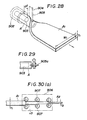
- the spreading machine 904 cuts the continuous tube A along the generatrix thereof with a cutting blade 905 or a cutting disk 905a (Fig. 29) disposed at a small distance from the free end of the core 903 to spread the continuous tube A in a continuous flat plate Al.
- the rolling mill 906 rolls the continuous flat plate Al having a thickness t1 and a width W1 into a thin and wide continuous flat plate A2 having a predetermined thickness t2 and a predetermined width W2 through a plurality of rollers, for example, three to five rollers.
- the roll gap ⁇ G between the plural rollers 907 is reduced in steps to reduce the thickness of the continuous flat plate Al gradually as illustrated in Figs. 30(a) and 30(b).
- the trimming machine 908 trims the continuous flat plate A2 to remove the irregular side edges of the continuous flat plate A2 to form a regular continuous flat plate A3.
- a conveying machine 909 having free rollers 909a, a driven conveyor belt 909b which is driven at a conveying speed corresponding to the delivering speed of the rolling mill 906, or a combination of the free rollers 909a and the driven conveyor belt 909b as illustrated in Fig. 3l.
- the conveying machine 909 conveys the continuous flat plate A3 without distorting the same to the next process.
Landscapes
- Engineering & Computer Science (AREA)
- Ceramic Engineering (AREA)
- Chemical & Material Sciences (AREA)
- Mechanical Engineering (AREA)
- Structural Engineering (AREA)
- Manufacturing & Machinery (AREA)
- Press-Shaping Or Shaping Using Conveyers (AREA)
- Devices For Post-Treatments, Processing, Supply, Discharge, And Other Processes (AREA)
Claims (15)
- Système de fabrication d'articles longs, continus, en céramique comprenant, en disposition linéaire successive :
une extrudeuse (2) qui extrude de façon continue un matériau vert (1) contenant de l'argile comme composant principal;
une machine de séchage (3) pour sécher une bande continue (A), extrudée par l'extrudeuse (2), en utilisant des rayons infrarouges, des micro-ondes ou la chaleur perdue d'un four de cuisson (5), comme source de chaleur;
une lame mobile (4) pour découper la bande continue (A) livrée par la machine de séchage (3), en donnant des plaques longues (A') sèches, de longueur prédéterminée;
une machine d'acheminement (14) pour acheminer les plaques longues sèches (A');
un four de cuisson (5) qui préchauffe de façon continue, cuit et refroidit les plaques longues sèches (A'); et
une machine de livraison (15) qui fournit les plaques longues (A') cuites, livrées par le four de cuisson (5), vers la suite du traitement, machine dans laquelle une buse (104) de l'extrudeuse (2) est pourvue d'un noyau en réseau creux (105), servant à former des cavités (8) dans la bande continue (A), et un ou plusieurs tubes (106), correspondant au nombre de branches de réseau du noyau en réseau (105), étant fixés à la partie avant ou arrière du noyau en réseau (105) pour faire écouler de l'air, de l'air chaud, de l'air très chaud, de l'air sec ou de la vapeur par les cavités (B) de la bande continue (A), caractérisé en ce que l'écoulement s'effectue dans le sens du déplacement de la bande continue (A) extrudée. - Système de fabrication d'articles longs continus en céramique, selon la revendication 1, dans lequel une machine à dresser (12), comprenant des rouleaux d'acheminement fous servant au guidage de la bande continue (A) allant, une fois dressée, vers l'étape suivante, et une machine d'acheminement (14), qui tire la bande continue (A) produite par la machine à dresser (12), à une vitesse d'acheminement légèrement supérieure à la vitesse d'extrusion de l'extrudeuse (2), pour acheminer la bande continue (A) sous tension vers l'étape suivante du processus, sont disposées entre l'extrudeuse (2) et la machine de séchage (3); ladite machine de séchage (3) comprenant des rouleaux d'acheminement fous disposés dans une zone de séchage, dans laquelle la teneur en eau de la bande continue (A) est réduite à peu près à 10 à 6%, et des rouleaux menés, entraînés à une vitesse d'acheminement correspondant à la vitesse de déplacement de la bande continue et disposés dans une autre zone de séchage, située après la zone de séchage précédente.
- Système de fabrication d'articles longs, continus, en céramique sel on la revendication 1, dans lequel ladite lame mobile (4) est pratiquement contigue à la sortie de ladite machine de séchage (3), et découpe la bande continue (A) produite par la machine de séchage (3) en donnant des plaques longues (A') sèches, de longueur prédéterminée.
- Système de fabrication d'articles longs, continus, en céramique selon la revendication 1, dans lequel une machine à émailler (13), servant à émailler les plaques longues (A') sèches, séchées par ladite machine de séchage (3) et découpées par ladite lame mobile (4), est disposée entre ladite lame mobile (4) et ledit four de cuisson (5).
- Système de fabrication d'articles longs, continus, en céramique selon la revendication 1, dans lequel ladite machine de séchage (3) comprend un unité de chauffage par micro-ondes (503) et une unité de chauffage par rayons infrarouges lointains (168) disposés dans cet ordre.
- Système de fabrication d'articles longs, continus, en céramique selon la revendication 1, dans lequel ledit ou lesdits tubes (106) est (sont) fixé(s) sur la partie avant, la partie arrière ou la paroi latérale dudit noyau en réseau (105).
- Système de fabrication d'articles longs, continus, en céramique selon la revendication 5, dans lequel ladite unité de chauffage par micro-ondes (503) est du type à four continu, qui réduit en un temps court la teneur en eau de la bande continue (A), extrudée par ladite extrudeuse (2), et ladite unité de chauffage par rayons infrarouges lointains (108) fonctionnant principalement pour élever la température de la bande continue (A), après que cette dernière ait été chauffée par l'unité de chauffage par micro-ondes (503).
- Système de fabrication d'articles longs, continus, en céramique selon la revendication 5, dans lequel ladite machine de séchage (3) comprend une pluralité de sections de chauffage, comprenant chacune une unité de chauffage par micro-ondes (503) et une unité de chauffage par rayons infrarouges lointains (108), disposées dans cet ordre.
- Système de fabrication d'articles longs, continus, en céramique selon la revendication 5, dans lequel ladite machine de séchage (3) présente une enceinte formant une chambre de chauffage et pourvue d'ouvertures d'amenée d'air, par lesquelles l'air est amené dans la chambre de chauffage pour décharger une grande quantité de vapeur produite par le chauffage de la bande continue (A) par la chambre de chauffage.
- Système de fabrication d'articles longs, continus, en céramique selon la revendication 7, dans lequel la machine d'acheminement (14), comprenant des rouleaux d'acheminement fous et une courroie d'acheminement menée, entraînée à une vitesse d'acheminement sensiblement égale à la vitesse d'extrusion de l'extrudeuse (2), est disposée entre ladite extrudeuse (2) et ladite unité de chauffage par micro-ondes (503) de type à four continu, servant à réduire en un temps court la teneur en eau de la bande continue (A), de façon à former un trajet d'acheminement situé en série avec le trajet s'étendant entre ladite extrudeuse (2) et ladite unité de chauffage par micro-ondes (503); cette dernière étant pourvue d'un mécanisme d'acheminement du système à rouleau d'acheminement fou; et ladite unité de chauffage par micro-ondes (503) ayant des ouvertures d'amenée d'air s'ouvrant dans la zone de chauffage par micro-ondes.
- Système de fabrication d'articles longs, continus, en céramique selon la revendication 1, dans lequel ledit four de cuisson (5) est du type à sole réfractaire et à rouleau.
- Système de fabrication d'articles longs, continus, en céramique selon la revendication 5, dans lequel ladite unité de chauffage par micro-ondes (503) comporte un transporteur à rouleau, comprenant des rouleaux fous, d'une construction qui ne causera ni étincelle ni surchauffe, pour guider et acheminer la bande continue destinée à être chauffée par l'unité de chauffage par micro-ondes (503); une pluralité de trous traversants (724) servant au passage des micro-ondes étant formés dans les parois verticales respectives des organes de support, servant à supporter les arbres respectifs des rouleaux d'acheminement fous; et des tôles de protection, de section transversale en forme de U, étant prévues le long des côtés opposés du transporteur à rouleau, de façon à recouvrir les surfaces supérieure et inférieure des bordures latérales de la bande continue (A).
- Système de fabrication d'articles longs, continus, en céramique selon la revendication 1, dans lequel une machine de perforation (7), servant à former des trous d'aération uniquement sur la bande continue (A), immédiatement après que cette dernière ait été extrudée par l'extrudeuse (2), est disposée entre l'extrudeuse (2) et la machine de séchage (3); et la machine à émailler (13) étant disposée entre la machine de séchage (3) et le four de cuisson (5).
- Système de fabrication d'articles longs, continus, en céramique selon la revendication 13, dans lequel ladite machine de perforation (7) comprend un rouleau de perforation (130), formé en fixant des picots sur la circonférence d'un rouleau, selon des intervalles circonférentiels et axiaux appropriés, et monté à rotation près de la buse (104) de l'extrudeuse (2).
- Système de fabrication d'articles longs, continus, en céramique selon la revendication 13, dans lequel ladite machine de perforation (7) comprend une plaque de perforation à dents (1041), disposée avant la buse (104) de l'extrudeuse (2), et entraînée grâce à une source d'entraînement pour effectuer des mouvements alternatifs verticaux et horizontaux.
Applications Claiming Priority (8)
| Application Number | Priority Date | Filing Date | Title |
|---|---|---|---|
| JP9422786A JPS62252359A (ja) | 1986-04-22 | 1986-04-22 | 長尺陶板の連続製造装置 |
| JP94227/86 | 1986-04-22 | ||
| JP21496186A JPS6369744A (ja) | 1986-09-10 | 1986-09-10 | 粘土成形体の迅速乾燥装置 |
| JP214961/86 | 1986-09-10 | ||
| JP215073/86 | 1986-09-11 | ||
| JP21507386A JPH0729842B2 (ja) | 1986-09-11 | 1986-09-11 | 粘土成形体の迅速乾燥装置 |
| JP222303/86 | 1986-09-20 | ||
| JP22230386A JPH0729844B2 (ja) | 1986-09-20 | 1986-09-20 | マイクロ波加熱装置 |
Publications (3)
| Publication Number | Publication Date |
|---|---|
| EP0242503A2 EP0242503A2 (fr) | 1987-10-28 |
| EP0242503A3 EP0242503A3 (en) | 1989-07-26 |
| EP0242503B1 true EP0242503B1 (fr) | 1991-11-27 |
Family
ID=27468200
Family Applications (1)
| Application Number | Title | Priority Date | Filing Date |
|---|---|---|---|
| EP87100639A Expired - Lifetime EP0242503B1 (fr) | 1986-04-22 | 1987-01-19 | Système de fabrication d'articles longs, continus en matière céramique |
Country Status (5)
| Country | Link |
|---|---|
| US (1) | US4764102A (fr) |
| EP (1) | EP0242503B1 (fr) |
| CA (1) | CA1296510C (fr) |
| DE (1) | DE3774751D1 (fr) |
| NZ (1) | NZ218984A (fr) |
Families Citing this family (41)
| Publication number | Priority date | Publication date | Assignee | Title |
|---|---|---|---|---|
| DE3826523A1 (de) * | 1988-08-04 | 1990-02-08 | Juergen Gerlach | Waermebehandlungseinrichtung fuer fortlaufend bewegtes material |
| US5057001A (en) * | 1989-03-10 | 1991-10-15 | The Carborundum Company | Apparatus for making ceramic tubes |
| AT393987B (de) * | 1990-01-15 | 1992-01-10 | Linser Peter | Schruehgebrannte platte zur herstellung von ofenkacheln |
| GB9004518D0 (en) * | 1990-02-28 | 1990-04-25 | Interdri Ltd | Ware drying |
| US5099096A (en) * | 1990-04-05 | 1992-03-24 | Martin Marietta Energy Systems, Inc. | Microwave furnace having microwave compatible dilatometer |
| US5108670A (en) * | 1990-04-20 | 1992-04-28 | Martin Marietta Energy Systems, Inc. | Process for making a titanium diboride-chromium diboride-yttrium titanium oxide ceramic composition |
| EP0525086A4 (en) * | 1990-04-20 | 1993-09-15 | Martin Marietta Energy Systems, Inc. | A method of nitriding refractory metal articles |
| US5164130A (en) * | 1990-04-20 | 1992-11-17 | Martin Marietta Energy Systems, Inc. | Method of sintering ceramic materials |
| US5013694A (en) * | 1990-04-20 | 1991-05-07 | Martin Marietta Energy Systems, Inc. | Titanium diboride-chromium diboride-yttrium titanium oxide ceramic composition and a process for making the same |
| US5154779A (en) * | 1990-04-20 | 1992-10-13 | Martin Marietta Energy Systems, Inc. | Method of nitriding, carburizing, or oxidizing refractory metal articles using microwaves |
| US5223188A (en) * | 1990-10-29 | 1993-06-29 | Corning Incorporated | Stiffening of extrudates with RF energy |
| JP3077879B2 (ja) * | 1994-02-15 | 2000-08-21 | インターナショナル・ビジネス・マシーンズ・コーポレ−ション | ウェブ・タイプの定量された処理材料にマイクロ波エネルギーを印加するための装置及び方法 |
| US5747747A (en) * | 1996-01-23 | 1998-05-05 | General Signal Corporation | Continuing belt-type conveyor and means for weighing contents transported thereon |
| JP2000500711A (ja) * | 1996-05-17 | 2000-01-25 | イムプリコ ベスローテン フェンノートシャップ | 焼結済み押出しセラミック製品の製法及びその製造装置 |
| US5882564A (en) * | 1996-06-24 | 1999-03-16 | Andersen Corporation | Resin and wood fiber composite profile extrusion method |
| US6107614A (en) * | 1997-09-05 | 2000-08-22 | Hed International Inc. | Continuous microwave furnace having a plurality of furnace modules forming an improved heating configuration |
| US20020174562A1 (en) * | 2001-05-23 | 2002-11-28 | Pearcy Timothy E. | Microwave lyophilization method |
| JP2004530627A (ja) * | 2001-06-14 | 2004-10-07 | ス、クンヒ | 酸化マグネシウムを用いた建材の成形方法 |
| EP1586407A4 (fr) * | 2003-01-21 | 2008-08-06 | Toyota Steel Ct Co Ltd | Dispositif de decoupe par laser, procede de decoupe par laser et systeme de decoupe par laser |
| EP1452504A3 (fr) * | 2003-02-05 | 2005-10-26 | Maké, Charlotte | Matériau pour eléments de construction, ainsi que les eléments de construction obtenus et procédé de fabrication de tels eléments de construction |
| ITBO20030087A1 (it) * | 2003-02-21 | 2004-08-22 | Ga Ma Italia S R L | Apparecchiatura elettrica per il trattamento termico dei capelli. |
| DE102004042143B3 (de) * | 2004-08-31 | 2006-02-16 | Eisenmann Maschinenbau Gmbh & Co. Kg | Verfahren zur Herstellung von Bauelementen, insbesondere von Bauplatten, aus Feststoffabfällen |
| ES2294919B1 (es) * | 2006-03-07 | 2009-02-16 | Consejo Superior Investig. Cientificas | Horno continuo con laser acoplado para el tratamiento superficial de materiales. |
| AU2008216380A1 (en) | 2007-02-13 | 2008-08-21 | John Desautels | A personal affector machine |
| HRPK20070080B3 (en) * | 2007-02-27 | 2010-02-28 | Plaščar Ivan | Apparatus for continuos production clay products |
| US8729436B2 (en) * | 2008-05-30 | 2014-05-20 | Corning Incorporated | Drying process and apparatus for ceramic greenware |
| IT1393379B1 (it) * | 2008-09-15 | 2012-04-20 | Siti B & T Group Spa | Metodo ed apparato per realizzare incavi su superfici di manufatti ceramici |
| IT1398653B1 (it) * | 2009-07-03 | 2013-03-08 | Siti B & T Group Spa | Procedimento di decoro per decorare manufatti ceramici |
| IT1396815B1 (it) * | 2009-12-04 | 2012-12-14 | Danieli Off Mecc | Dispositivo e procedimento per alimentare materiale metallico in un impianto di fusione |
| IT1397387B1 (it) * | 2009-12-11 | 2013-01-10 | Siti B & T Group Spa | Apparato e metodo di consolidamento. |
| EP2937653B1 (fr) * | 2010-02-25 | 2018-12-12 | Corning Incorporated | Ensembles de support et procédés de fabrication d'articles en céramique |
| WO2014054168A1 (fr) * | 2012-10-05 | 2014-04-10 | イビデン株式会社 | Procédé de découpe de corps séché en nid d'abeilles, procédé de production d'une structure en nid d'abeilles, corps séché en nid d'abeilles et structure en nid d'abeilles |
| US20140260401A1 (en) * | 2013-03-14 | 2014-09-18 | Simon James SHAMOUN | Hot product impingement freezer with impingement belt apparatus |
| TWI579060B (zh) * | 2014-10-30 | 2017-04-21 | 位元奈米科技股份有限公司 | 用於透明基板之金屬塗料層的烘乾方法及其裝置 |
| KR20170043936A (ko) * | 2015-10-14 | 2017-04-24 | 현대자동차주식회사 | 블랭크 가열 장치 |
| JP6821421B2 (ja) * | 2016-12-21 | 2021-01-27 | ケイミュー株式会社 | 押出成形型 |
| IT201700045233A1 (it) * | 2017-04-26 | 2018-10-26 | Sacmi | Forno e metodo per la cottura di articoli ceramici di base |
| CN110271085A (zh) * | 2019-07-22 | 2019-09-24 | 株洲聚润合微波工业炉有限公司 | 一种微波续热辊轧生产发泡陶瓷板的短流程设备及方法 |
| CN114919053B (zh) * | 2022-05-23 | 2024-07-02 | 氢环环保科技(上海)有限公司 | 连续式人造大理石制造装置及制造方法 |
| ES2959122A1 (es) * | 2022-07-21 | 2024-02-20 | Exagres S A | Procedmiento y dispositivo para la fabricacion de piezas ceramicas |
| CN115338960B (zh) * | 2022-08-01 | 2023-12-19 | 广东家美陶瓷有限公司 | 陶瓷岩板增强增韧方法、背网铺设方法及热熔设备 |
Family Cites Families (22)
| Publication number | Priority date | Publication date | Assignee | Title |
|---|---|---|---|---|
| LU28801A1 (fr) * | ||||
| US658534A (en) * | 1899-02-16 | 1900-09-25 | H B Camp Company | Device for perforating tiles. |
| US1248963A (en) * | 1917-08-24 | 1917-12-04 | Fisk Rubber Co | Tubing-die. |
| US1348932A (en) * | 1918-10-28 | 1920-08-10 | Dochnal Frank | Manufacturing of hollow tile and the like |
| US1945306A (en) * | 1932-05-24 | 1934-01-30 | Dean John | Machine and method for producing wall board |
| US2647295A (en) * | 1948-09-20 | 1953-08-04 | Robert E Gould | Method and apparatus for manufacture of pottery |
| US2682081A (en) * | 1951-02-28 | 1954-06-29 | Richard A Fisch | Method of producing a striated extruded tubing |
| GB930708A (en) * | 1960-04-16 | 1963-07-10 | Fetok Gmbh | Improvements relating to facing tiles |
| FR1324971A (fr) * | 1962-03-12 | 1963-04-26 | Plastus S A | Nouveau procédé de fabrication par extrusion de tubes en matériau plastique |
| FR1495459A (fr) * | 1966-05-24 | 1967-09-22 | Const Mecaniques Et Commandes | Poutre de céramique cellulaire et son procédé de fabrication |
| GB1442484A (en) * | 1973-04-24 | 1976-07-14 | Nippon Synthetic Chem Ind | Process for preparing fire-resisting mouldings |
| US4013403A (en) * | 1975-12-08 | 1977-03-22 | Pullman Incorporated | Support means for a roller hearth in a kiln |
| GB1529165A (en) * | 1977-06-23 | 1978-10-18 | Miyakita I | Apparatus for cutting continuously moving sheet material by jet stream of fluid under high pressure |
| US4183760A (en) * | 1977-11-18 | 1980-01-15 | Electric Power Research Institute, Inc. | High-strength alumina ceramic product and method of forming |
| US4289945A (en) * | 1979-10-17 | 1981-09-15 | Whirlpool Corporation | Energy transmission and distribution system for a microwave oven |
| DE3104499C2 (de) * | 1981-02-09 | 1983-04-07 | Rosenthal Ag, 8672 Selb | Verfahren und Vorrichtung zum Trocknen von keramischen Formlingen |
| US4374079A (en) * | 1981-03-04 | 1983-02-15 | Hancor, Inc. | Method and apparatus for manufacturing expanded and layered semiround plastic tubings |
| IT1147425B (it) * | 1981-10-14 | 1986-11-19 | Carfer Srl | Forno ceramico a rulli a combustione e raffreddamento modulati |
| GB2112318B (en) * | 1981-12-22 | 1985-10-23 | Wienerberger Baustoffind Ag | Process and apparatus for the production of articles consisting of ceramic material |
| GB2137552B (en) * | 1983-04-08 | 1987-04-23 | Asahi Chemical Ind | Reducing residual strain in extruded and rolled ceramic plates |
| DE3406789C1 (de) * | 1984-02-24 | 1989-07-20 | Adolf 7251 Weissach Berkmann | Verfahren zum Trocknen von insbesondere pulverbeschichteten Werkstuecken durch Infrarotstrahlung |
| US4626641A (en) * | 1984-12-04 | 1986-12-02 | James River Corporation | Fruit and meat pie microwave container and method |
-
1987
- 1987-01-16 US US07/004,054 patent/US4764102A/en not_active Expired - Fee Related
- 1987-01-19 DE DE8787100639T patent/DE3774751D1/de not_active Expired - Fee Related
- 1987-01-19 EP EP87100639A patent/EP0242503B1/fr not_active Expired - Lifetime
- 1987-01-20 NZ NZ218984A patent/NZ218984A/xx unknown
- 1987-01-20 CA CA000527651A patent/CA1296510C/fr not_active Expired - Fee Related
Also Published As
| Publication number | Publication date |
|---|---|
| EP0242503A2 (fr) | 1987-10-28 |
| US4764102A (en) | 1988-08-16 |
| DE3774751D1 (de) | 1992-01-09 |
| CA1296510C (fr) | 1992-03-03 |
| NZ218984A (en) | 1989-03-29 |
| EP0242503A3 (en) | 1989-07-26 |
Similar Documents
| Publication | Publication Date | Title |
|---|---|---|
| EP0242503B1 (fr) | Système de fabrication d'articles longs, continus en matière céramique | |
| US7290405B2 (en) | Method and apparatus for conducting heat to a glass sheet | |
| CN2932256Y (zh) | 一种微波连续干燥生产线 | |
| JP2713909B2 (ja) | 陶板の製造装置 | |
| JPH0729833B2 (ja) | 中空陶板の連続製造装置 | |
| JPH0527585B2 (fr) | ||
| JPH0729832B2 (ja) | 長尺陶板の製造装置 | |
| SU1036128A1 (ru) | Установка дл конвективно-радиационной сушки длинномерных материалов | |
| JPH0729839B2 (ja) | 長尺セラミツク板の製造方法 | |
| JPH0729845B2 (ja) | 中空粘土成形体の迅速乾燥装置 | |
| JPS63176348A (ja) | 長尺陶板の製造装置 | |
| JP2859687B2 (ja) | 陶板の製造方法 | |
| JPS6317250A (ja) | 長尺陶板の連続製造装置 | |
| JP2837230B2 (ja) | 陶板の製造装置 | |
| JP2886580B2 (ja) | 長尺セラミック体の製造装置 | |
| JPH0729834B2 (ja) | 陶板製造装置 | |
| JPH0477696B2 (fr) | ||
| JPH0729837B2 (ja) | 長尺陶板の連続製造装置 | |
| JPH0660051B2 (ja) | 長尺陶板の連続製造装置 | |
| JPH0460068B2 (fr) | ||
| JPS63218532A (ja) | 陶板の製造装置 | |
| JPS63190749A (ja) | 長尺陶板の製造装置 | |
| JPH0725085B2 (ja) | 長尺セラミツク板の製造方法 | |
| JPH0729846B2 (ja) | 粘土成形体用のマイクロ波加熱装置 | |
| JPH0729831B2 (ja) | 長尺陶板の連続製造装置 |
Legal Events
| Date | Code | Title | Description |
|---|---|---|---|
| PUAI | Public reference made under article 153(3) epc to a published international application that has entered the european phase |
Free format text: ORIGINAL CODE: 0009012 |
|
| 17P | Request for examination filed |
Effective date: 19870119 |
|
| AK | Designated contracting states |
Kind code of ref document: A2 Designated state(s): DE FR GB IT |
|
| PUAL | Search report despatched |
Free format text: ORIGINAL CODE: 0009013 |
|
| AK | Designated contracting states |
Kind code of ref document: A3 Designated state(s): DE FR GB IT |
|
| 17Q | First examination report despatched |
Effective date: 19900216 |
|
| GRAA | (expected) grant |
Free format text: ORIGINAL CODE: 0009210 |
|
| AK | Designated contracting states |
Kind code of ref document: B1 Designated state(s): DE FR GB IT |
|
| ITF | It: translation for a ep patent filed | ||
| REF | Corresponds to: |
Ref document number: 3774751 Country of ref document: DE Date of ref document: 19920109 |
|
| ET | Fr: translation filed | ||
| PLBE | No opposition filed within time limit |
Free format text: ORIGINAL CODE: 0009261 |
|
| STAA | Information on the status of an ep patent application or granted ep patent |
Free format text: STATUS: NO OPPOSITION FILED WITHIN TIME LIMIT |
|
| 26N | No opposition filed | ||
| PGFP | Annual fee paid to national office [announced via postgrant information from national office to epo] |
Ref country code: GB Payment date: 19960104 Year of fee payment: 10 |
|
| PGFP | Annual fee paid to national office [announced via postgrant information from national office to epo] |
Ref country code: FR Payment date: 19960116 Year of fee payment: 10 |
|
| PGFP | Annual fee paid to national office [announced via postgrant information from national office to epo] |
Ref country code: DE Payment date: 19960229 Year of fee payment: 10 |
|
| PG25 | Lapsed in a contracting state [announced via postgrant information from national office to epo] |
Ref country code: GB Effective date: 19970119 |
|
| GBPC | Gb: european patent ceased through non-payment of renewal fee |
Effective date: 19970119 |
|
| PG25 | Lapsed in a contracting state [announced via postgrant information from national office to epo] |
Ref country code: FR Effective date: 19970930 |
|
| PG25 | Lapsed in a contracting state [announced via postgrant information from national office to epo] |
Ref country code: DE Effective date: 19971001 |
|
| REG | Reference to a national code |
Ref country code: FR Ref legal event code: ST |
|
| PG25 | Lapsed in a contracting state [announced via postgrant information from national office to epo] |
Ref country code: IT Free format text: LAPSE BECAUSE OF NON-PAYMENT OF DUE FEES;WARNING: LAPSES OF ITALIAN PATENTS WITH EFFECTIVE DATE BEFORE 2007 MAY HAVE OCCURRED AT ANY TIME BEFORE 2007. THE CORRECT EFFECTIVE DATE MAY BE DIFFERENT FROM THE ONE RECORDED. Effective date: 20050119 |