EP0242602A2 - Lentille électrostatique et magnétique pour appareils à faisceau corpusculaire - Google Patents
Lentille électrostatique et magnétique pour appareils à faisceau corpusculaire Download PDFInfo
- Publication number
- EP0242602A2 EP0242602A2 EP87104111A EP87104111A EP0242602A2 EP 0242602 A2 EP0242602 A2 EP 0242602A2 EP 87104111 A EP87104111 A EP 87104111A EP 87104111 A EP87104111 A EP 87104111A EP 0242602 A2 EP0242602 A2 EP 0242602A2
- Authority
- EP
- European Patent Office
- Prior art keywords
- electrostatic
- magnetic lens
- magnetic
- lens
- lens according
- Prior art date
- Legal status (The legal status is an assumption and is not a legal conclusion. Google has not performed a legal analysis and makes no representation as to the accuracy of the status listed.)
- Granted
Links
Images
Classifications
-
- H—ELECTRICITY
- H01—ELECTRIC ELEMENTS
- H01J—ELECTRIC DISCHARGE TUBES OR DISCHARGE LAMPS
- H01J37/00—Discharge tubes with provision for introducing objects or material to be exposed to the discharge, e.g. for the purpose of examination or processing thereof
- H01J37/02—Details
- H01J37/04—Arrangements of electrodes and associated parts for generating or controlling the discharge, e.g. electron-optical arrangement or ion-optical arrangement
- H01J37/10—Lenses
- H01J37/145—Combinations of electrostatic and magnetic lenses
Definitions
- the invention relates to an electrostatic-magnetic lens for corpuscular beam devices.
- the resolution of a scanning electron microscope specified by the beam diameter d on the sample is essentially determined at low acceleration voltages by the Coulomb repulsion of the electrons counteracting the focusing (Boersch effect) and the axial color error of the imaging lenses, according to the relationship given below with the color error coefficient C F and with a constant width of the energy distribution of the electrons, increases with decreasing primary energy.
- d F C F ⁇ ⁇ ⁇ ⁇ U / U depends on the beam aperture, the color error coefficient C F of the lens, the primary energy eU and the width of the energy distribution e ⁇ ⁇ U of the electrons.
- the invention is based on the object of specifying a lens for corpuscular beam devices with which high-energy corpuscles can be braked to a desired final energy and which has smaller color and aperture error constants than conventional magnetic lenses. This object is achieved by an electrostatic-magnetic lens according to claim 1.
- the advantage that can be achieved with the invention is, in particular, that corpuscular probes with a small beam cross section can be produced even with high beam currents and low acceleration voltages.
- Claims 2 to 10 are directed to preferred refinements and developments of the invention.
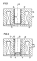
- FIGS. 1 to 4 show electrostatic-magnetic lenses according to the invention.
- the electrostatic-magnetic lens shown in Fig. 1 consists of a symmetrical or asymmetrical magnetic lens ML, which is always an electrostatic sion lens is superimposed.
- the magnetic flux generated with the aid of the excitation coil SP is guided over the pole shoes UP and OP and concentrated in a small space around the axis of symmetry OA of the system, the magnetic field being rotationally symmetrical about this axis having its maximum strength in the pole shoe gap PS reached.
- an electrode of the immersion lens is designed in the form of a hollow cylinder RE, which, together with a likewise cylindrical insulator IS, is arranged in the upper pole shoe OP of the magnetic lens ML concentrically with the axis of symmetry OA thereof, and extends into the region of the pole shoe gap PS.
- the lower pole piece of the magnetic lens ML which is preferably at ground potential and, as shown in FIG. 2, can be lined with a beam guiding tube SF made of magnetic or non-magnetic material for protection against contamination, forms the lower electrode of the electrostatic immersion lens according to the invention.
- a rotationally symmetrical electrical delay field builds up inside the magnetic lens ML whenever the cylinder electrode RE is placed at a positive potential with respect to the lower pole shoe UP, in particular at the potential of the anode of the corpuscular beam generator.
- the imaging properties of the corpuscular-optical unit consisting of an electrostatic immersion lens and a magnetic lens are essentially determined by the voltages of the electrodes and their dimensions and the magnetic field strength in the pole shoe gap PS. It is therefore in no way necessary for the cylinder electrode RE and the lower pole shoe opening to have the same diameter.
- the focal length of the electrostatic immersion lens can thus be changed with the aid of a circular pinhole BL, which is arranged inside the cylinder electrode RE or, as shown in FIG. 2, closes in the region of the pole shoe gap PS.
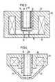
- a continuous change in the focal length is possible if two coaxial cylindrical electrodes RE or SE of different lengths are arranged in the upper pole shoe OP and the external cylinder electrode SE acting as a control electrode is subjected to suitable voltages (see FIG. 3).
- Each of the cylinder electrodes RE or SE can again be closed off by a circular pinhole BL.
- the electrostatic-magnetic lenses according to the invention Due to the electrical delay field superimposed on the focusing magnetic field, the electrostatic-magnetic lenses according to the invention have significantly smaller opening and color error constants than magnetic individual lenses.
- the error constants of the composite system which are essentially determined by the potential difference between cylinder electrode RE and lower pole shoe UP, are reduced by a factor of 10 compared to the error constants of the magnetic single lens, for example, if the corpuscles in the electrical retardation field of the immersion lens are reduced to 1/10 decelerates their primary energy (kinetic energy in the beam path directly above the lens according to the invention).
- the lenses according to the invention also have the advantage that their easily computable corpuscular-optical properties can be implemented very well in practice due to the excellent centerability of the electrical and magnetic lens.
- FIG. 4 An electrostatic-magnetic lens with a conical magnetic lens ML is shown in Fig. 4, in the same Beziers Schweizer same arrangement elements as in Figs. 1 to 3 denote.
- Conical objective lenses are used, for example, in scanning electron microscopes in order to be able to image and examine large-area specimens even in the tilted state with a small working distance. Due to their pole shoe shape, however, conical magnetic lenses have a large gap PS and thus a comparatively long focal length, which leads to relatively large opening and color error constants which increase with the focal length.
- the arrangement according to the invention of a cylindrical electrode RE lying at positive potential in the upper pole shoe OP significantly improves the imaging properties of the corpuscular-optical unit consisting of conical magnetic lens ML and electrostatic immersion lens compared to the conical single lens.
- This improvement in the imaging properties can be achieved by reducing the error constants already described and shifting the main planes of the conical magnetic lens ML towards the sample, which has smaller aberrations due to the associated shortening of the focal length (C F ⁇ focal length).
- the lower pole shoe UP which is preferably at ground potential, again forms an electrode of the electrostatic immersion lens.
- the electrostatic-magnetic lenses according to the invention are advantageously used in scanning particle microscopes, in particular in scanning electron microscopes, in which the Boersch effect limits the resolution, in particular at low acceleration voltages, and conventional lens systems have excessive aberrations. Since the influence of the lateral Boersch effect on the probe diameter decreases at high kinetic energies, the width of the energy distribution of the primary electrons is particularly due to the beam generator of the energetic Boersch effect increases significantly, the electrons should pass through the first beam crossing point (sources crossover) advantageously with low energies (e.g. 2 keV) in order to then accelerate them to high energies (e.g. 10 keV) and only shortly before reaching the sample to the desired low final energy (for example 1 keV).
- sources crossover advantageously with low energies (e.g. 2 keV) in order to then accelerate them to high energies (e.g. 10 keV) and only shortly before reaching the sample to the desired low final energy (for example 1 keV).
- the braking and focusing of the primary electrons is advantageously carried out with the aid of an electrostatic-magnetic lens according to the invention, which replaces one of the conventional condenser lenses or the objective lens in the electron-optical column and whose cylinder electrode RE accelerates the primary electrons at an assumed cathode potential of - 1 kV 10 keV and a desired final energy of the primary electrons from 1 keV to anode potential, that is to 9 kV.
Landscapes
- Chemical & Material Sciences (AREA)
- Analytical Chemistry (AREA)
- Electron Beam Exposure (AREA)
- Treatments Of Macromolecular Shaped Articles (AREA)
- Eyeglasses (AREA)
- Hard Magnetic Materials (AREA)
- Physical Or Chemical Processes And Apparatus (AREA)
Priority Applications (1)
| Application Number | Priority Date | Filing Date | Title |
|---|---|---|---|
| AT87104111T ATE91822T1 (de) | 1986-04-24 | 1987-03-20 | Elektrostatisch-magnetische-linse fuer korpuskularstrahlgeraete. |
Applications Claiming Priority (2)
| Application Number | Priority Date | Filing Date | Title |
|---|---|---|---|
| DE3613915 | 1986-04-24 | ||
| DE3613915 | 1986-04-24 |
Publications (3)
| Publication Number | Publication Date |
|---|---|
| EP0242602A2 true EP0242602A2 (fr) | 1987-10-28 |
| EP0242602A3 EP0242602A3 (en) | 1989-09-06 |
| EP0242602B1 EP0242602B1 (fr) | 1993-07-21 |
Family
ID=6299463
Family Applications (1)
| Application Number | Title | Priority Date | Filing Date |
|---|---|---|---|
| EP87104111A Expired - Lifetime EP0242602B1 (fr) | 1986-04-24 | 1987-03-20 | Lentille électrostatique et magnétique pour appareils à faisceau corpusculaire |
Country Status (6)
| Country | Link |
|---|---|
| US (1) | US4785176A (fr) |
| EP (1) | EP0242602B1 (fr) |
| JP (1) | JPH0624106B2 (fr) |
| AT (1) | ATE91822T1 (fr) |
| CA (1) | CA1264873A (fr) |
| DE (1) | DE3786588D1 (fr) |
Cited By (2)
| Publication number | Priority date | Publication date | Assignee | Title |
|---|---|---|---|---|
| EP0790634A1 (fr) * | 1996-02-16 | 1997-08-20 | ACT Advanced Circuit Testing Gesellschaft für Testsystementwicklung mbH | Dispositif de lentille électrostatique-magnétique |
| US6949744B2 (en) | 2003-04-17 | 2005-09-27 | Carl Zeiss Nts Gmbh | Electron microscopy system, electron microscopy method and focusing system for charged particles |
Families Citing this family (38)
| Publication number | Priority date | Publication date | Assignee | Title |
|---|---|---|---|---|
| DE3766092D1 (de) * | 1986-12-12 | 1990-12-13 | Integrated Circuit Testing | Detektoranordnung mit einem detektorobjektiv fuer korpuskularstrahlgeraete. |
| KR920000941B1 (ko) * | 1988-02-16 | 1992-01-31 | 후지쓰 가부시끼가이샤 | 전자빔 노광장치 |
| US4926054A (en) * | 1988-03-17 | 1990-05-15 | Ict Integrated Circuit Testing Gesellschaft Fur Halbleiterpruftechnik Mbh | Objective lens for focusing charged particles in an electron microscope |
| US5041731A (en) * | 1989-01-20 | 1991-08-20 | Fujitsu Limited | Deflection compensating device for converging lens |
| JP2882412B2 (ja) | 1989-01-20 | 1999-04-12 | 富士通株式会社 | 電子ビーム露光装置 |
| EP0432337B1 (fr) * | 1989-12-13 | 1994-08-03 | International Business Machines Corporation | Microlentille delta-phi pour faisceau de particules à basse énergie |
| JPH071681B2 (ja) * | 1990-04-19 | 1995-01-11 | 株式会社日立製作所 | 荷電粒子線装置 |
| US5146090A (en) * | 1990-06-11 | 1992-09-08 | Siemens Aktiengesellschaft | Particle beam apparatus having an immersion lens arranged in an intermediate image of the beam |
| JP2777840B2 (ja) * | 1990-11-30 | 1998-07-23 | セイコーインスツルメンツ株式会社 | 電子線装置 |
| US5629526A (en) * | 1993-09-28 | 1997-05-13 | Nikon Corporation | Electro-magnetic lens, charged particle beam transferring apparatus, and method for manufacturing electro-magnetic lens |
| JP3942108B2 (ja) * | 1994-04-12 | 2007-07-11 | エフイーアイ カンパニー | 二次電子用検出器を具えた粒子‐光学装置 |
| US5644132A (en) * | 1994-06-20 | 1997-07-01 | Opan Technologies Ltd. | System for high resolution imaging and measurement of topographic and material features on a specimen |
| US5614833A (en) * | 1994-10-25 | 1997-03-25 | International Business Machines Corporation | Objective lens with large field deflection system and homogeneous large area secondary electron extraction field |
| DE4438315A1 (de) * | 1994-10-26 | 1996-05-02 | Siemens Ag | Vorrichtung zum Entfernen von Ionen aus einem Elektronenstrahl |
| DE69638126D1 (de) * | 1995-10-19 | 2010-04-01 | Hitachi Ltd | Rasterelektronenmikroskop |
| JPH09147779A (ja) * | 1995-11-20 | 1997-06-06 | Nikon Corp | 電磁偏向器 |
| US5780859A (en) * | 1996-02-16 | 1998-07-14 | Act Advanced Circuit Testing Gesellschaft | Electrostatic-magnetic lens arrangement |
| JP3580060B2 (ja) * | 1996-05-09 | 2004-10-20 | 富士ゼロックス株式会社 | 印刷制御装置及び方法 |
| DE19732093B4 (de) * | 1997-07-25 | 2008-09-25 | Carl Zeiss Nts Gmbh | Korpuskularstrahlgerät |
| US6069363A (en) * | 1998-02-26 | 2000-05-30 | International Business Machines Corporation | Magnetic-electrostatic symmetric doublet projection lens |
| KR100489911B1 (ko) * | 1999-12-14 | 2005-05-17 | 어플라이드 머티어리얼스, 인코포레이티드 | 하전 입자 빔을 사용하여 표본을 검사하는 방법 및 시스템 |
| US6960766B2 (en) * | 2000-02-25 | 2005-11-01 | Hermes-Microvision, Inc. | Swinging objective retarding immersion lens electron optics focusing, deflection and signal collection system and method |
| US6392231B1 (en) | 2000-02-25 | 2002-05-21 | Hermes-Microvision, Inc. | Swinging objective retarding immersion lens electron optics focusing, deflection and signal collection system and method |
| US7800062B2 (en) * | 2002-06-11 | 2010-09-21 | Applied Materials, Inc. | Method and system for the examination of specimen |
| DE10237297A1 (de) * | 2002-08-14 | 2004-03-11 | Leo Elektronenmikroskopie Gmbh | Teilchenoptische Vorrichtung, Elektronenmikroskopiesystem und Lithogrphiesystem |
| JP2004134388A (ja) * | 2002-08-13 | 2004-04-30 | Leo Elektronenmikroskopie Gmbh | 粒子光学装置、電子顕微鏡システムおよび電子リソグラフィーシステム |
| US7528614B2 (en) | 2004-12-22 | 2009-05-05 | Applied Materials, Inc. | Apparatus and method for voltage contrast analysis of a wafer using a tilted pre-charging beam |
| NL1023260C1 (nl) * | 2003-04-24 | 2004-10-27 | Fei Co | Deeltjes-optisch apparaat met een permanent magnetische lens en een elektrostatische lens. |
| EP1777728A1 (fr) * | 2005-10-20 | 2007-04-25 | Carl Zeiss SMS GmbH | Sytème lithographique |
| KR101384260B1 (ko) * | 2005-12-05 | 2014-04-11 | 전자빔기술센터 주식회사 | 전자칼럼의 전자빔 포커싱 방법 |
| DE102007010873B4 (de) * | 2007-03-06 | 2009-07-30 | Carl Zeiss Nts Gmbh | Objektivlinse |
| JP4977509B2 (ja) * | 2007-03-26 | 2012-07-18 | 株式会社日立ハイテクノロジーズ | 走査電子顕微鏡 |
| US8319192B2 (en) | 2010-08-24 | 2012-11-27 | Hermes Microvision Inc. | Charged particle apparatus |
| US9922796B1 (en) * | 2016-12-01 | 2018-03-20 | Applied Materials Israel Ltd. | Method for inspecting a specimen and charged particle multi-beam device |
| US10777382B2 (en) | 2017-11-21 | 2020-09-15 | Focus-Ebeam Technology (Beijing) Co., Ltd. | Low voltage scanning electron microscope and method for specimen observation |
| US10504684B1 (en) * | 2018-07-12 | 2019-12-10 | ICT Integrated Circuit Testing Gesellschaft für Halbleiterprüftechnik mbH | High performance inspection scanning electron microscope device and method of operating the same |
| CN114220725B (zh) | 2020-12-02 | 2024-05-07 | 聚束科技(北京)有限公司 | 一种电子显微镜 |
| CN114256043B (zh) | 2020-12-02 | 2024-04-05 | 聚束科技(北京)有限公司 | 一种电子束系统 |
Family Cites Families (6)
| Publication number | Priority date | Publication date | Assignee | Title |
|---|---|---|---|---|
| DE1012398B (de) * | 1943-11-27 | 1957-07-18 | Dr Heinrich Herbst | Elektronenoptisches Linsensystem fuer Elektronen- oder Ionenmikroskope |
| NL177578C (nl) * | 1976-05-14 | 1985-10-16 | Thomson Csf | Inrichting voor het beschrijven van een voorwerp met een deeltjesbundel. |
| JPS57118357A (en) * | 1981-01-14 | 1982-07-23 | Jeol Ltd | Objective lens for scan type electron microscope |
| DE3138992A1 (de) * | 1981-09-30 | 1983-04-14 | Siemens AG, 1000 Berlin und 8000 München | Abtastverfahren zur schnellen potentialbestimmung inder elektronenstrahl-messtechnik |
| GB2115976A (en) * | 1982-02-26 | 1983-09-14 | Philips Electronic Associated | Charged particle beam apparatus |
| US4713543A (en) * | 1984-08-13 | 1987-12-15 | Siemens Aktiengesellschaft | Scanning particle microscope |
-
1987
- 1987-03-20 AT AT87104111T patent/ATE91822T1/de not_active IP Right Cessation
- 1987-03-20 EP EP87104111A patent/EP0242602B1/fr not_active Expired - Lifetime
- 1987-03-20 DE DE8787104111T patent/DE3786588D1/de not_active Expired - Lifetime
- 1987-03-27 US US07/030,964 patent/US4785176A/en not_active Expired - Lifetime
- 1987-04-20 JP JP62097253A patent/JPH0624106B2/ja not_active Expired - Fee Related
- 1987-04-22 CA CA000535238A patent/CA1264873A/fr not_active Expired - Lifetime
Cited By (2)
| Publication number | Priority date | Publication date | Assignee | Title |
|---|---|---|---|---|
| EP0790634A1 (fr) * | 1996-02-16 | 1997-08-20 | ACT Advanced Circuit Testing Gesellschaft für Testsystementwicklung mbH | Dispositif de lentille électrostatique-magnétique |
| US6949744B2 (en) | 2003-04-17 | 2005-09-27 | Carl Zeiss Nts Gmbh | Electron microscopy system, electron microscopy method and focusing system for charged particles |
Also Published As
| Publication number | Publication date |
|---|---|
| JPH0624106B2 (ja) | 1994-03-30 |
| ATE91822T1 (de) | 1993-08-15 |
| EP0242602B1 (fr) | 1993-07-21 |
| JPS62256352A (ja) | 1987-11-09 |
| DE3786588D1 (de) | 1993-08-26 |
| EP0242602A3 (en) | 1989-09-06 |
| US4785176A (en) | 1988-11-15 |
| CA1264873A (fr) | 1990-01-23 |
Similar Documents
| Publication | Publication Date | Title |
|---|---|---|
| EP0242602B1 (fr) | Lentille électrostatique et magnétique pour appareils à faisceau corpusculaire | |
| EP0461442B1 (fr) | Appareil à faisceau de particules | |
| EP0333018B1 (fr) | Lentille d'objectif pour la focalisation de particules chargées | |
| EP0274622B1 (fr) | Assemblage de détecteur avec un objectif muni d'un détecteur pour instruments à rayons corpusculaires | |
| EP0281743B1 (fr) | Objectif détecteur pour microscope à balayage | |
| DE10233002B4 (de) | Objektivlinse für ein Elektronenmikroskopiesystem und Elektronenmikroskopiesystem | |
| EP0267555B1 (fr) | Objectif de spectromètre pour appareils de mesure par faisceau corpusculaire et procédé pour l'examen d'échantillons. | |
| EP1220292B1 (fr) | Monochromateur pour particules chargées | |
| EP0180723B1 (fr) | Dispositif corpusculaire à rayonnement | |
| EP0205184B1 (fr) | Objectif de faible aberration comportant un spectromètre de haute acceptance en électrons secondaires | |
| DE3222275C2 (de) | Ablenk- und Fokussiersystem für einen Strahl aus geladenen Teilchen | |
| DE3841715A1 (de) | Abbildender korrektor vom wien-typ fuer elektronenmikroskope | |
| EP0893816A2 (fr) | Appareil à faisceau corpusculaire | |
| EP0194570A2 (fr) | Microscope corpusculaire à balayage à effet Boersch réduit | |
| DE112015001235B4 (de) | Vorrichtung und verfahren zur abbildung mittels eines elektronenstrahls unter verwendung eines monochromators mit doppeltem wien-filter sowie monochromator | |
| DE10056482A1 (de) | Säule mit energiegefiltertem, fokussierten Ionenstrahl | |
| DE60105199T2 (de) | Sem mit einem sekundärelektronendetektor mit einer zentralelektrode | |
| EP0910109B1 (fr) | Lentille objectif | |
| EP0205185B1 (fr) | Objectif comportant un spectromètre en technique de mesure par faisceau d'électrons | |
| EP0910108B1 (fr) | Lentille pour faisceau d'électrons | |
| EP0236807A2 (fr) | Objectif de spectromètre en technique de mesure par faisceau corpusculaire | |
| DE19746785A1 (de) | Teilchenstrahlgerät mit Energiefilter | |
| DE3703028A1 (de) | Rastermikroskop | |
| DE3438987C2 (fr) | ||
| DE102004019835B4 (de) | Beleuchtungskondensor für ein Partikeloptik-Projektionssystem |
Legal Events
| Date | Code | Title | Description |
|---|---|---|---|
| PUAI | Public reference made under article 153(3) epc to a published international application that has entered the european phase |
Free format text: ORIGINAL CODE: 0009012 |
|
| AK | Designated contracting states |
Kind code of ref document: A2 Designated state(s): AT CH DE FR GB IT LI NL SE |
|
| PUAL | Search report despatched |
Free format text: ORIGINAL CODE: 0009013 |
|
| AK | Designated contracting states |
Kind code of ref document: A3 Designated state(s): AT CH DE FR GB IT LI NL SE |
|
| RAP1 | Party data changed (applicant data changed or rights of an application transferred) |
Owner name: ICT INTEGRATED CIRCUIT TESTING GESELLSCHAFT FUER H |
|
| 17P | Request for examination filed |
Effective date: 19900220 |
|
| 17Q | First examination report despatched |
Effective date: 19920630 |
|
| GRAA | (expected) grant |
Free format text: ORIGINAL CODE: 0009210 |
|
| AK | Designated contracting states |
Kind code of ref document: B1 Designated state(s): AT CH DE FR GB IT LI NL SE |
|
| REF | Corresponds to: |
Ref document number: 91822 Country of ref document: AT Date of ref document: 19930815 Kind code of ref document: T |
|
| ITF | It: translation for a ep patent filed | ||
| REF | Corresponds to: |
Ref document number: 3786588 Country of ref document: DE Date of ref document: 19930826 |
|
| GBT | Gb: translation of ep patent filed (gb section 77(6)(a)/1977) |
Effective date: 19930816 |
|
| ET | Fr: translation filed | ||
| PG25 | Lapsed in a contracting state [announced via postgrant information from national office to epo] |
Ref country code: AT Effective date: 19940320 |
|
| PG25 | Lapsed in a contracting state [announced via postgrant information from national office to epo] |
Ref country code: SE Free format text: LAPSE BECAUSE OF NON-PAYMENT OF DUE FEES Effective date: 19940321 |
|
| PG25 | Lapsed in a contracting state [announced via postgrant information from national office to epo] |
Ref country code: CH Effective date: 19940331 Ref country code: LI Effective date: 19940331 |
|
| PLBE | No opposition filed within time limit |
Free format text: ORIGINAL CODE: 0009261 |
|
| STAA | Information on the status of an ep patent application or granted ep patent |
Free format text: STATUS: NO OPPOSITION FILED WITHIN TIME LIMIT |
|
| 26N | No opposition filed | ||
| REG | Reference to a national code |
Ref country code: CH Ref legal event code: PL |
|
| EUG | Se: european patent has lapsed |
Ref document number: 87104111.7 Effective date: 19941010 |
|
| REG | Reference to a national code |
Ref country code: FR Ref legal event code: TP |
|
| REG | Reference to a national code |
Ref country code: GB Ref legal event code: 732E |
|
| REG | Reference to a national code |
Ref country code: GB Ref legal event code: 732E |
|
| NLS | Nl: assignments of ep-patents |
Owner name: ADVANTEST CORPORATION;ACT ADVANCED CIRCUIT TESTING |
|
| REG | Reference to a national code |
Ref country code: FR Ref legal event code: TP |
|
| REG | Reference to a national code |
Ref country code: GB Ref legal event code: 732E |
|
| NLS | Nl: assignments of ep-patents |
Owner name: ADVANTEST CORPORATION |
|
| REG | Reference to a national code |
Ref country code: FR Ref legal event code: TP |
|
| REG | Reference to a national code |
Ref country code: GB Ref legal event code: IF02 |
|
| PG25 | Lapsed in a contracting state [announced via postgrant information from national office to epo] |
Ref country code: IT Free format text: LAPSE BECAUSE OF NON-PAYMENT OF DUE FEES;WARNING: LAPSES OF ITALIAN PATENTS WITH EFFECTIVE DATE BEFORE 2007 MAY HAVE OCCURRED AT ANY TIME BEFORE 2007. THE CORRECT EFFECTIVE DATE MAY BE DIFFERENT FROM THE ONE RECORDED. Effective date: 20050320 |
|
| PGFP | Annual fee paid to national office [announced via postgrant information from national office to epo] |
Ref country code: FR Payment date: 20060209 Year of fee payment: 20 |
|
| PGFP | Annual fee paid to national office [announced via postgrant information from national office to epo] |
Ref country code: GB Payment date: 20060213 Year of fee payment: 20 |
|
| PGFP | Annual fee paid to national office [announced via postgrant information from national office to epo] |
Ref country code: NL Payment date: 20060215 Year of fee payment: 20 |
|
| PGFP | Annual fee paid to national office [announced via postgrant information from national office to epo] |
Ref country code: DE Payment date: 20060526 Year of fee payment: 20 |
|
| PG25 | Lapsed in a contracting state [announced via postgrant information from national office to epo] |
Ref country code: GB Free format text: LAPSE BECAUSE OF EXPIRATION OF PROTECTION Effective date: 20070319 |
|
| PG25 | Lapsed in a contracting state [announced via postgrant information from national office to epo] |
Ref country code: NL Free format text: LAPSE BECAUSE OF EXPIRATION OF PROTECTION Effective date: 20070320 |
|
| REG | Reference to a national code |
Ref country code: GB Ref legal event code: PE20 |
|
| NLV7 | Nl: ceased due to reaching the maximum lifetime of a patent |
Effective date: 20070320 |