EP0243061B1 - Interrupteur autonome avec batterie de réserve - Google Patents
Interrupteur autonome avec batterie de réserve Download PDFInfo
- Publication number
- EP0243061B1 EP0243061B1 EP19870303204 EP87303204A EP0243061B1 EP 0243061 B1 EP0243061 B1 EP 0243061B1 EP 19870303204 EP19870303204 EP 19870303204 EP 87303204 A EP87303204 A EP 87303204A EP 0243061 B1 EP0243061 B1 EP 0243061B1
- Authority
- EP
- European Patent Office
- Prior art keywords
- energy
- power
- source
- winding
- primary
- Prior art date
- Legal status (The legal status is an assumption and is not a legal conclusion. Google has not performed a legal analysis and makes no representation as to the accuracy of the status listed.)
- Expired - Lifetime
Links
Images


Classifications
-
- H—ELECTRICITY
- H02—GENERATION; CONVERSION OR DISTRIBUTION OF ELECTRIC POWER
- H02J—ELECTRIC POWER NETWORKS; CIRCUIT ARRANGEMENTS OR SYSTEMS FOR SUPPLYING OR DISTRIBUTING ELECTRIC POWER; SYSTEMS FOR STORING ELECTRIC ENERGY
- H02J9/00—Circuit arrangements for emergency or stand-by power supply, e.g. for emergency lighting
- H02J9/04—Circuit arrangements for emergency or stand-by power supply, e.g. for emergency lighting in which the distribution system is disconnected from the normal source and connected to a standby source
- H02J9/06—Circuit arrangements for emergency or stand-by power supply, e.g. for emergency lighting in which the distribution system is disconnected from the normal source and connected to a standby source with automatic change-over, e.g. UPS systems
- H02J9/062—Circuit arrangements for emergency or stand-by power supply, e.g. for emergency lighting in which the distribution system is disconnected from the normal source and connected to a standby source with automatic change-over, e.g. UPS systems for AC powered loads
-
- H—ELECTRICITY
- H02—GENERATION; CONVERSION OR DISTRIBUTION OF ELECTRIC POWER
- H02J—ELECTRIC POWER NETWORKS; CIRCUIT ARRANGEMENTS OR SYSTEMS FOR SUPPLYING OR DISTRIBUTING ELECTRIC POWER; SYSTEMS FOR STORING ELECTRIC ENERGY
- H02J9/00—Circuit arrangements for emergency or stand-by power supply, e.g. for emergency lighting
- H02J9/04—Circuit arrangements for emergency or stand-by power supply, e.g. for emergency lighting in which the distribution system is disconnected from the normal source and connected to a standby source
- H02J9/06—Circuit arrangements for emergency or stand-by power supply, e.g. for emergency lighting in which the distribution system is disconnected from the normal source and connected to a standby source with automatic change-over, e.g. UPS systems
- H02J9/067—Circuit arrangements for emergency or stand-by power supply, e.g. for emergency lighting in which the distribution system is disconnected from the normal source and connected to a standby source with automatic change-over, e.g. UPS systems using multi-primary transformers, e.g. transformer having one primary for each AC energy source and a secondary for the loads
Definitions
- This invention relates to switching type power supplies.
- Uninterruptible power supplies have generally assumed either a serial or parallel architecture.
- a serial architecture format a rectifier, battery and inverter are connected in tandem with the AC line, with the battery floating when the AC source input to the rectifier is satisfactory.
- This arrangement is generally satisfactory, but is inefficient since the overall efficiency can be no higher than the product of the efficiencies of the tandem connected components.
- failure of any of the tandem connected components may cause the entire power supply to fail.
- the parallel architecture format avoids many of the disadvantages of the serial architecture format, since the two sources of energy are fully independent of each other. While efficiency and reliability is improved, the control arrangement for substituting the load from one power source to the other is more complex; especially in those applications where a load transfer must be transient free and transparent to the load. The control arrangement must maintain synchronism and a definite phase relation between the two power processing paths. While these parallel architecture arrangements can be made cost effective at relative high power levels, the added control circuitry and complex transformer design requirements mitigate against their widespread use at relatively low power levels.
- US-A-4564767 discloses an uninterruptible switching power supply having a first primary input energized by rectified AC line voltage and a second reserve input energized by a battery voltage.
- the power modulating switch associated with the second input is operative as a power switch only when the AC voltage has failed. Separate circuitry is needed to sense the failure of the primary input and to engage the power switch processing the reserve battery voltage.
- the present invention seeks to provide a simplified control arrangement for parallel architecture arrangements.
- the respective winding turns of the primary winding, the secondary and the auxiliary winding may be selected so that output voltage regulation for the primary and secondary voltage sources is effective over substantially different input voltage ranges that include a small common overlap range.
- the regulated output voltage is derived solely from the primary AC voltage source. If this line voltage source is degraded in magnitude, regulation control slips into the overlap range in which both primary and secondary voltage sources contribute to the output power. Should primary power fail entirely, the output power is supplied solely from the secondary voltage source.
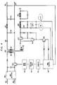
- FIG. 1 An off-line switcher designed to be energized by AC line voltage is shown in FIG. 1. It includes provisions for supplying power to a load at output terminal 10 from one or both of two independent sources of power.
- Source 1 representing a commercial AC line is coupled to a rectifier filter circuit 11.
- Circuit 11 is coupled to a diode 2 which is operative to prevent reverse power flow from winding 21 when the input voltage is low.
- the secondary or reserve power source 12 is illustratively shown as a battery and is coupled to winding 22 through diode 3, which prevents reverse power flow into battery 12. Power flow from either the AC source 1, or source 12, is through power transformer 20 to one or more outputs, such as terminal 10.
- Power flow from the primary AC input source 1 is coupled to a primary winding 21 by power switch 13, whereas power flow from the secondary source 12 is coupled to an auxiliary winding 22 by power switch 14.
- Voltage regulation at output 10 is controlled by a pulse width modulation control (PWM) 30.
- PWM pulse width modulation control
- the output voltage is sensed at output terminal 10 and a pulse control signal shown by waveform 101 in FIG. 2 is coupled, via a primary to secondary isolation coupler 31, to logic circuit 32.
- Coupler 31 may comprise an optical coupler, a pulse transformer, or any other transmission medium capable of maintaining ground isolation.
- This pulse control signal is utilized by logic circuit 32 to supply timing signals to base drive 33 to control the duty cycle of the power switch 13 as shown by waveform 103 in FIG. 2.
- Power switch 13 may comprise a bipolar power transistor or a FET power transistor, but is not necessarily limited to these devices.
- Voltage pulse waveform 103 used to control the drive of power switch 13 has variable pulse width. This pulse width is controlled by PWM control 30 in order to regulate the voltage output at output terminal 10.
- the output of PWM control 30 is also applied to base drive 34 to control a duty cycle of power switch 14 (either a bipolar or FET, or the like) which couples the reserve voltage source 12 to the auxiliary winding 22.
- the duty cycle of power switch 14 is shown by waveform 102 in FIG. 2.
- the different duty cycles of waveforms 102 and 103 are disclosed to illustratively show typical duty cycles at which the AC voltage source 1 and DC voltage source 12 normally supply power to the output.
- Both power switches 13 and 14 are simultaneously driven at a common duty cycle, and for a certain range, as shown by waveform 101 between edges 8 and 9, both switches couple power to the output. To the left of edge 8 only the switch 13 couples power to the output and to the right of edge 9 only the power switch 14 couples power to the output.
- the resultant voltage output 10 is derived from different voltage sources of differing output voltage ranges, such as shown in FIG. 3, wherein lines 301 and 302 represent voltage level boundaries of the rectified DC operative input voltage range supplied from AC primary voltage source 1 via rectifier 11, and lines 303 and 304 represent boundaries of an operative input voltage range supplied by the secondary source 12. As shown, the voltage ranges are different except for a small overlap between lines 302 and 303.
- Line 305 represents an alarm level at which an alarm indicating low AC line voltage is signaled if the voltage drops below this level.
- the differing voltage ranges are achieved by control of source voltage levels and by differing transformation ratios between primary winding 21 to secondary winding 23 and between auxiliary winding 22 to secondary winding 23.
- the output voltage is defined by the equation: where: V O is the output voltage, V P is the rectified AC line voltage, and D is the duty cycle at which the power switches 13 and 14 are operated.
- this value is normally less that 1/2.
- the invention may be embodied in other types of converters such as flyback converters, for example.
- V O and D are as defined above;
- V B is the reserve voltage;
- the output voltage is dependent upon the turns ratio in the transformer coupled power flow path from source to the output if both primary and secondary voltage sources are identical.
- the turns ratio in the primary power path is selected so that the control 30 regulates over a generally higher input voltage range than that for the reserve power path.
- a drop in AC line voltage first causes control 30 to increase the duty cycle of both power switches to maintain the regulated output voltage. If the AC line voltage continues dropping, the output voltage is partially maintained by power from the reserve voltage source in the overlap region between lines 302 and 303 in FIG.
- FIG. 4 An off-line switcher operating as a forward type converter and providing reserve battery power is schematically disclosed in FIG. 4.
- Primary power supplied from an AC line source, is coupled to input terminals 401 and 402 and is rectified and filtered by rectifier/filter circuitry 404.
- a connection to the primary winding 405 of transformer 406 is periodically completed by the power switching transistor 403.
- the rectified DC output at leads 411 and 412 is derived from secondary winding 407 and rectified by diode 408.
- Diode 409 provides a flyback path for the output filter inductor 410.
- the output voltage is sensed across the filter capacitor 413 by a pulse width modulation controller 430, from which control signals are transmitted via coupler 431 to a logic circuit 432 which, in turn, controls timing of a drive circuit 433 to control the duty cycle of power switching transistor 403 in order to regulate the output voltage across the filter capacitor 413.
- a battery 451 is utilized as a reserve energy source and is coupled to an auxiliary winding 415 of power transformer 406 by a Darlington connected power transistor switch 453 (or power FET) whose switching is under control of base drive transistor 455 which is in turn responsive to an output of the PWM control 430.
- the duty cycle of power switch 453 is in synchronism with and substantially identical to the duty cycle of power switch 403.
- the reserve energy supplied by battery 451 is current limited.
- a current transformer 456 is utilized to sense the peak discharge current flowing from the battery 451 to the transistor switch 453. This current signal is rectified by diode 457 and filter 458 to derive a DC control signal. This control signal is coupled to the PWM controller 430 via leads 461 and 462 and is utilized through the controller 430 to provide overload protection.
Landscapes
- Business, Economics & Management (AREA)
- Emergency Management (AREA)
- Engineering & Computer Science (AREA)
- Power Engineering (AREA)
- Stand-By Power Supply Arrangements (AREA)
- Dc-Dc Converters (AREA)
Claims (2)
- Une alimentation du type à découpage comprenant un transformateur de puissance (20) ayant un enroulement primaire (21), un enroulement secondaire (23) et un enroulement auxiliaire (22), et ayant un premier rapport de transformation entre l'enroulement primaire et l'enroulement secondaire, et un second rapport de transformation entre l'enroulement auxiliaire et l'enroulement secondaire, des premiers moyens d'entrée (11, 13) destinés à être connectés à une source d'énergie primaire, des seconds moyens d'entrée (3, 14) destinés à être connectés à une source d'énergie secondaire (12), et des moyens de sortie (10) destinés à transmettre de l'énergie de l'enroulement secondaire vers une charge, les premiers moyens d'entrée comprenant un premier élément de commutation de puissance (13) qui connecte périodiquement la source d'énergie primaire à l'enroulement primaire, et CARACTERISEE EN CE QUE les seconds moyens d'entrée comprennent un second élément de commutation de puissance (14) qui est destiné à connecter périodiquement et continuellement la source d'énergie secondaire à l'enroulement auxiliaire, et en ce qu'elle comporte des moyens de commande de régulation (30) qui réagissent au niveau d'un signal que l'alimentation produit dans les moyens de sortie, en attaquant continuellement et simultanément les premier et second éléments de commutation de puissance avec un rapport cyclique commun, grâce à quoi, pendant le fonctionnement, des signaux de puissance sont continuellement appliqués aux moyens de sortie par l'intermédiaire des premier et second éléments de commutation, sous la commande des premier et second rapports de transformation dans des première et seconde plages de tension d'entrée, de façon que de l'énergie soit automatiquement fournie aux moyens de sortie à partir de la source d'énergie primaire dans la première plage de tension d'entrée, et que de l'énergie soit automatiquement fournie aux moyens de sortie à partir de la source d'énergie secondaire dans la seconde plage de tension d'entrée, lorsque la source d'énergie primaire est au-dessous de sa limite de fonctionnement désirée.
- Une alimentation du type à découpage selon la revendication 1, comprenant une batterie (figure 4, 451) pour la source d'énergie secondaire, et un circuit de contrôle comprenant un transformateur de détection (456) pour détecter un courant de décharge de la batterie.
Applications Claiming Priority (2)
| Application Number | Priority Date | Filing Date | Title |
|---|---|---|---|
| US853173 | 1986-04-17 | ||
| US06/853,173 US4745299A (en) | 1986-04-17 | 1986-04-17 | Off-line switcher with battery reserve |
Publications (3)
| Publication Number | Publication Date |
|---|---|
| EP0243061A2 EP0243061A2 (fr) | 1987-10-28 |
| EP0243061A3 EP0243061A3 (en) | 1989-08-02 |
| EP0243061B1 true EP0243061B1 (fr) | 1993-06-30 |
Family
ID=25315270
Family Applications (1)
| Application Number | Title | Priority Date | Filing Date |
|---|---|---|---|
| EP19870303204 Expired - Lifetime EP0243061B1 (fr) | 1986-04-17 | 1987-04-13 | Interrupteur autonome avec batterie de réserve |
Country Status (5)
| Country | Link |
|---|---|
| US (1) | US4745299A (fr) |
| EP (1) | EP0243061B1 (fr) |
| JP (1) | JPS62296728A (fr) |
| CA (1) | CA1314932C (fr) |
| DE (1) | DE3786366T2 (fr) |
Families Citing this family (52)
| Publication number | Priority date | Publication date | Assignee | Title |
|---|---|---|---|---|
| FR2614737B1 (fr) * | 1987-04-29 | 1989-06-09 | Cit Alcatel | Alimentation en energie electrique continue secourue avec une signalisation de l'etat de secours par inversion de polarite |
| DE3736372C1 (de) * | 1987-10-27 | 1989-01-05 | Nixdorf Computer Ag | Schaltnetzteil |
| US4908523A (en) * | 1988-04-04 | 1990-03-13 | Motorola, Inc. | Electronic circuit with power drain control |
| DE3816944A1 (de) * | 1988-05-18 | 1989-11-30 | Nixdorf Computer Ag | Spannungsversorgungssystem mit mehreren spannungsquellen |
| GB2219449B (en) * | 1988-05-31 | 1992-12-09 | Toshiba Kk | Air conditioning system having voltage drop countermeasure battery |
| FR2634329B1 (fr) * | 1988-07-12 | 1990-10-19 | France Ocean Exploration | Dispositif d'alimentation electrique secourue |
| US4825350A (en) * | 1988-07-21 | 1989-04-25 | General Electric Company | Method and apparatus for detecting a reduction in the input voltage to a power supply |
| JPH0747962Y2 (ja) * | 1989-02-20 | 1995-11-01 | 株式会社ピーエフユー | 停電補償形スイッチング・レギュレータ |
| JPH0398431A (ja) * | 1989-09-08 | 1991-04-24 | Pfu Ltd | バッテリーバックアップ型無停電電源装置 |
| IE75374B1 (en) * | 1989-11-13 | 1997-09-10 | Nat Csf Corp | Uninterruptible power supply |
| US5168436A (en) * | 1990-09-26 | 1992-12-01 | Allied-Signal Inc. | Uninterruptible power supply |
| US5857391A (en) * | 1992-03-02 | 1999-01-12 | Ndc Netzler & Dahlgren Co. Ab | Device for cutting a protective layer away from a material roll |
| US5739595A (en) * | 1992-10-28 | 1998-04-14 | Alpha Technologies, Inc. | Apparatus and methods for generating an AC power signal for cable tv distribution systems |
| US5642002A (en) * | 1993-10-29 | 1997-06-24 | Alpha Technologies | Apparatus and methods for generating uninterruptible AC power signals |
| US6204573B1 (en) * | 1994-01-05 | 2001-03-20 | Motorola, Inc. | Method and circuit for maintaining charge in a backup battery |
| GB9400499D0 (en) * | 1994-01-12 | 1994-03-09 | Magnum Power Solutions Ltd | Improved uninterruptible power supply |
| US5532525A (en) * | 1994-06-02 | 1996-07-02 | Albar, Inc. | Congeneration power system |
| US5751564A (en) * | 1994-08-10 | 1998-05-12 | Dien; Ghing-Hsin | Dual/multiple voltage level input switching power supply |
| GB9500969D0 (en) * | 1995-01-18 | 1995-03-08 | Magnum Power Solutions Ltd | Uninterruptible power supplies |
| CA2168520C (fr) * | 1995-02-22 | 2003-04-08 | Fereydoun Mekanik | Circuit onduleur/chargeur pour sources d'alimentation secourue |
| US5610451A (en) * | 1995-11-30 | 1997-03-11 | Magnum Power Plc | Uninterruptible power supply with power factor correction |
| US7269034B2 (en) | 1997-01-24 | 2007-09-11 | Synqor, Inc. | High efficiency power converter |
| JP2002514378A (ja) | 1997-01-24 | 2002-05-14 | シンクォール・インコーポレーテッド | 高効率電力変換装置 |
| JP3038652B2 (ja) * | 1997-05-28 | 2000-05-08 | 日本電気株式会社 | 無停電電源装置 |
| US6400043B1 (en) * | 1998-11-30 | 2002-06-04 | American Power Conversion Corporation | Modular uninterruptable power supply |
| US6348777B1 (en) * | 2000-02-29 | 2002-02-19 | Alaris Medical Systems, Inc. | Power management system |
| AT411506B (de) * | 2000-10-02 | 2004-01-26 | Siemens Ag Oesterreich | Schaltwandler |
| JP3470695B2 (ja) * | 2000-11-15 | 2003-11-25 | 株式会社村田製作所 | スイッチング電源装置およびそれを用いた電子装置 |
| EP1227565A1 (fr) * | 2001-01-25 | 2002-07-31 | Marconi Communications GmbH | Dispositif d'alimentation |
| US7034413B1 (en) * | 2002-08-12 | 2006-04-25 | Network Appliance, Inc. | Holdup time extender and inrush current eliminator for switching power supplies |
| JP3094731U (ja) * | 2002-12-17 | 2003-07-04 | 船井電機株式会社 | Rcc方式スイッチング電源およびrcc方式スイッチング電源を有するビデオカセットレコーダ |
| DE102004018502B3 (de) * | 2004-04-14 | 2006-01-12 | Phoenix Contact Gmbh & Co. Kg | Vorrichtung zur unterbrechungsfreien Stromversorgung |
| TW200919902A (en) * | 2007-10-23 | 2009-05-01 | Tpk Touch Solutions Inc | Dual-power loop auto-switch circuit system |
| US8575779B2 (en) * | 2010-02-18 | 2013-11-05 | Alpha Technologies Inc. | Ferroresonant transformer for use in uninterruptible power supplies |
| DE102010003797A1 (de) * | 2010-04-09 | 2011-10-13 | Tridonic Ag | Modulares LED-Beleuchtungssystem mit Notlichtfunktion |
| DE102010042328A1 (de) * | 2010-10-12 | 2012-04-12 | Robert Bosch Gmbh | Verfahren zum Überwachen des Ladebetriebs eines Energiespeichers in einem Fahrzeug und Ladesystem zum Laden eines Energiespeichers in einem Fahrzeug |
| WO2012148512A1 (fr) | 2011-01-23 | 2012-11-01 | Alpha Technologies Inc. | Systèmes et procédé de commutation pour alimentation électrique non interruptible |
| BR112013018804A2 (pt) | 2011-01-23 | 2020-09-01 | Alpha Technologies Inc. | fontes de alimentação ininterruptíveis para uso em uma rede distribuída |
| US20120257426A1 (en) * | 2011-04-11 | 2012-10-11 | Ever Win International Corporation | AC Adapter With Automatic Built-In Power Switch |
| US9450452B2 (en) | 2012-04-03 | 2016-09-20 | Micorsoft Technology Licensing, LLC | Transformer coupled current capping power supply topology |
| US9234916B2 (en) | 2012-05-11 | 2016-01-12 | Alpha Technologies Inc. | Status monitoring cables for generators |
| US10199950B1 (en) | 2013-07-02 | 2019-02-05 | Vlt, Inc. | Power distribution architecture with series-connected bus converter |
| US10033210B2 (en) | 2014-01-30 | 2018-07-24 | Micrsoft Technology Licensing, LLC | Power supply for use with a slow-response power source |
| US10050548B2 (en) * | 2014-09-29 | 2018-08-14 | The Boeing Company | No-break power transfer |
| JP6297225B2 (ja) * | 2015-07-21 | 2018-03-20 | 三菱電機株式会社 | 車両間伝送装置 |
| EP3347979A4 (fr) | 2015-09-13 | 2019-01-16 | Alpha Technologies Inc. | Systèmes et procédés de commande d'alimentation |
| US10381867B1 (en) | 2015-10-16 | 2019-08-13 | Alpha Technologeis Services, Inc. | Ferroresonant transformer systems and methods with selectable input and output voltages for use in uninterruptible power supplies |
| RU176677U1 (ru) * | 2017-06-05 | 2018-01-25 | Федеральное государственное автономное образовательное учреждение высшего образования "Уральский федеральный университет имени первого Президента России Б.Н. Ельцина" (УрФУ) | Устройство для автоматического включения выключателя резервной линии электропередачи |
| FR3068836B1 (fr) * | 2017-07-07 | 2019-08-23 | Stmicroelectronics (Rousset) Sas | Circuit de protection d'un commutateur de puissance |
| EP3652604A4 (fr) | 2017-07-14 | 2021-03-17 | Alpha Technologies Services, Inc. | Systèmes et procédés d'alimentation en courant alternatif à régulation de tension |
| RU183849U1 (ru) * | 2018-04-02 | 2018-10-05 | Федеральное государственное автономное образовательное учреждение высшего образования "Уральский федеральный университет имени первого Президента России Б.Н. Ельцина" | Устройство для автоматического включения выключателя резервной линии электропередачи двухстороннего действия |
| RU2698402C1 (ru) | 2018-08-30 | 2019-08-26 | Самсунг Электроникс Ко., Лтд. | Способ обучения сверточной нейронной сети для восстановления изображения и система для формирования карты глубины изображения (варианты) |
Family Cites Families (17)
| Publication number | Priority date | Publication date | Assignee | Title |
|---|---|---|---|---|
| US3614461A (en) * | 1969-08-11 | 1971-10-19 | Gen Electric Canada | Circuit for keeping the frequency of an inverter synchronized with the frequency of another source |
| US3771012A (en) * | 1972-05-24 | 1973-11-06 | Gen Electric | Battery protective circuit for emergency lighting systems |
| US3873846A (en) * | 1972-09-07 | 1975-03-25 | Sony Corp | Power supply system |
| US3778634A (en) * | 1973-05-18 | 1973-12-11 | Foxboro Co | Power supply with battery backup |
| US3986097A (en) * | 1975-06-30 | 1976-10-12 | Bell Telephone Laboratories, Incorporated | Bilateral direct current converters |
| DE2645507A1 (de) * | 1975-10-13 | 1977-04-14 | Tokyo Shibaura Electric Co | Elektrischer leistungswandler fuer aus einer akkumulatorenbatterie gespeiste elektrofahrzeuge |
| US4038559A (en) * | 1976-01-23 | 1977-07-26 | Bell Telephone Laboratories, Incorporated | Regulated uninterruptible power supply |
| GB1559788A (en) * | 1976-07-05 | 1980-01-23 | Post Office | Power supply apparatus |
| SE419015B (sv) * | 1979-11-01 | 1981-07-06 | Jungner Ab Nife | Forfarande for drift av en avbrottsfri stromforsorjningsanleggning samt avbrottsfri stromforsorjningsanleggning for genomforande av forfarandet |
| US4388534A (en) * | 1981-08-11 | 1983-06-14 | Computer Power, Inc. | Uninterruptible power supply |
| FR2513031B1 (fr) * | 1981-09-17 | 1986-01-24 | Fontaine Ets Pierre | Perfectionnements apportes aux procedes et aux dispositifs d'alimentation electrique alternative d'une charge, sans discontinuite du signal alternatif |
| JPS59175347A (ja) * | 1983-03-24 | 1984-10-04 | ニシム電子工業株式会社 | 交流無停電電源装置 |
| US4564767A (en) * | 1983-11-07 | 1986-01-14 | Tii Industries, Inc. | Uninterruptible switching power supply system |
| US4561046A (en) * | 1983-12-22 | 1985-12-24 | Gte Automatic Electric Incorporated | Single transistor forward converter with lossless magnetic core reset and snubber network |
| US4623960A (en) * | 1984-10-15 | 1986-11-18 | At&T Bell Laboratories | Bias power source energized by tertiary winding including hysteresis characteristic for disabling the power switch when a minimum base drive signal can no longer be maintained |
| US4673825A (en) * | 1985-02-15 | 1987-06-16 | Exide Electronics Corporation | Uninterruptible power supply with isolated bypass winding |
| US4631471A (en) * | 1985-03-25 | 1986-12-23 | At&T Bell Laboratories | Inductor apparatus for application of ferroresonant regulators |
-
1986
- 1986-04-17 US US06/853,173 patent/US4745299A/en not_active Expired - Lifetime
-
1987
- 1987-04-13 DE DE87303204T patent/DE3786366T2/de not_active Expired - Fee Related
- 1987-04-13 EP EP19870303204 patent/EP0243061B1/fr not_active Expired - Lifetime
- 1987-04-16 CA CA 534962 patent/CA1314932C/fr not_active Expired - Fee Related
- 1987-04-17 JP JP62093439A patent/JPS62296728A/ja active Pending
Also Published As
| Publication number | Publication date |
|---|---|
| DE3786366T2 (de) | 1993-10-14 |
| JPS62296728A (ja) | 1987-12-24 |
| EP0243061A2 (fr) | 1987-10-28 |
| EP0243061A3 (en) | 1989-08-02 |
| US4745299A (en) | 1988-05-17 |
| DE3786366D1 (de) | 1993-08-05 |
| CA1314932C (fr) | 1993-03-23 |
Similar Documents
| Publication | Publication Date | Title |
|---|---|---|
| US4745299A (en) | Off-line switcher with battery reserve | |
| EP0804827B1 (fr) | Alimentation electrique sans coupure | |
| EP1034614B1 (fr) | Convertisseur de frequence et alimentation electrique sans coupure | |
| EP3242387B1 (fr) | Appareil de commande d'alimentation pour sous-module de convertisseur mmc | |
| US4809151A (en) | Switching regulator having parallel diode isolated primary windings and plural secondary windings | |
| EP0973246A1 (fr) | Contrôleur pour redresseur synchrone et convertisseur de puissance employant ce contrôleur | |
| WO2002067409A2 (fr) | Procede et circuit permettant de reduire les courants inverses dans un circuit convertisseur redresseur synchrone | |
| US5633564A (en) | Modular uninterruptible lighting system | |
| EP1001513B1 (fr) | Convertisseur de puissance à découpage universel | |
| CN1144343C (zh) | 开关电源 | |
| US4517470A (en) | High frequency inverter | |
| CN116529998A (zh) | 移相全桥转换器 | |
| US6134122A (en) | Integrated voltage and current mode controller for a power converter and method of operation thereof | |
| US6480400B2 (en) | Power supply apparatus | |
| EP0602950B1 (fr) | Dispositif de commande pour limiter la tension d'une capacité d'annulation de flux de noyau magnétique | |
| JP3254667B2 (ja) | スイッチング電源制御装置 | |
| JP3145260B2 (ja) | 空気調和機 | |
| CN85106900A (zh) | 用于电视接收机的电源电路装置 | |
| EP0794608A2 (fr) | Alimentation de puissance cyclique | |
| EP4387066A1 (fr) | Convertisseur abaisseur-élévateur pour commande de contacteur | |
| EP1227565A1 (fr) | Dispositif d'alimentation | |
| JPH05219650A (ja) | 負荷変動対応電源装置 | |
| JPH0241632A (ja) | 多重化電源システム | |
| HK1003528B (en) | Uninterruptible power supplies | |
| JPH03245729A (ja) | 情報処理装置の給電システム |
Legal Events
| Date | Code | Title | Description |
|---|---|---|---|
| PUAI | Public reference made under article 153(3) epc to a published international application that has entered the european phase |
Free format text: ORIGINAL CODE: 0009012 |
|
| AK | Designated contracting states |
Kind code of ref document: A2 Designated state(s): DE GB IT NL SE |
|
| PUAL | Search report despatched |
Free format text: ORIGINAL CODE: 0009013 |
|
| AK | Designated contracting states |
Kind code of ref document: A3 Designated state(s): DE GB IT NL SE |
|
| 17P | Request for examination filed |
Effective date: 19900124 |
|
| 17Q | First examination report despatched |
Effective date: 19910809 |
|
| GRAA | (expected) grant |
Free format text: ORIGINAL CODE: 0009210 |
|
| AK | Designated contracting states |
Kind code of ref document: B1 Designated state(s): DE GB IT NL SE |
|
| REF | Corresponds to: |
Ref document number: 3786366 Country of ref document: DE Date of ref document: 19930805 |
|
| ITF | It: translation for a ep patent filed | ||
| PLBE | No opposition filed within time limit |
Free format text: ORIGINAL CODE: 0009261 |
|
| STAA | Information on the status of an ep patent application or granted ep patent |
Free format text: STATUS: NO OPPOSITION FILED WITHIN TIME LIMIT |
|
| 26N | No opposition filed | ||
| EAL | Se: european patent in force in sweden |
Ref document number: 87303204.9 |
|
| PGFP | Annual fee paid to national office [announced via postgrant information from national office to epo] |
Ref country code: GB Payment date: 19970210 Year of fee payment: 11 |
|
| PGFP | Annual fee paid to national office [announced via postgrant information from national office to epo] |
Ref country code: SE Payment date: 19970217 Year of fee payment: 11 |
|
| PGFP | Annual fee paid to national office [announced via postgrant information from national office to epo] |
Ref country code: DE Payment date: 19970228 Year of fee payment: 11 |
|
| PGFP | Annual fee paid to national office [announced via postgrant information from national office to epo] |
Ref country code: NL Payment date: 19970430 Year of fee payment: 11 |
|
| PG25 | Lapsed in a contracting state [announced via postgrant information from national office to epo] |
Ref country code: GB Free format text: LAPSE BECAUSE OF NON-PAYMENT OF DUE FEES Effective date: 19980413 |
|
| PG25 | Lapsed in a contracting state [announced via postgrant information from national office to epo] |
Ref country code: SE Free format text: LAPSE BECAUSE OF NON-PAYMENT OF DUE FEES Effective date: 19980414 |
|
| PG25 | Lapsed in a contracting state [announced via postgrant information from national office to epo] |
Ref country code: NL Free format text: LAPSE BECAUSE OF NON-PAYMENT OF DUE FEES Effective date: 19981101 |
|
| GBPC | Gb: european patent ceased through non-payment of renewal fee |
Effective date: 19980413 |
|
| NLV4 | Nl: lapsed or anulled due to non-payment of the annual fee |
Effective date: 19981101 |
|
| EUG | Se: european patent has lapsed |
Ref document number: 87303204.9 |
|
| PG25 | Lapsed in a contracting state [announced via postgrant information from national office to epo] |
Ref country code: DE Free format text: LAPSE BECAUSE OF NON-PAYMENT OF DUE FEES Effective date: 19990202 |
|
| PG25 | Lapsed in a contracting state [announced via postgrant information from national office to epo] |
Ref country code: IT Free format text: LAPSE BECAUSE OF NON-PAYMENT OF DUE FEES;WARNING: LAPSES OF ITALIAN PATENTS WITH EFFECTIVE DATE BEFORE 2007 MAY HAVE OCCURRED AT ANY TIME BEFORE 2007. THE CORRECT EFFECTIVE DATE MAY BE DIFFERENT FROM THE ONE RECORDED. Effective date: 20050413 |