EP0247453B1 - Magnetisches Plattengerät oder System - Google Patents
Magnetisches Plattengerät oder System Download PDFInfo
- Publication number
- EP0247453B1 EP0247453B1 EP87107026A EP87107026A EP0247453B1 EP 0247453 B1 EP0247453 B1 EP 0247453B1 EP 87107026 A EP87107026 A EP 87107026A EP 87107026 A EP87107026 A EP 87107026A EP 0247453 B1 EP0247453 B1 EP 0247453B1
- Authority
- EP
- European Patent Office
- Prior art keywords
- access control
- control circuits
- actuators
- actuator
- control means
- Prior art date
- Legal status (The legal status is an assumption and is not a legal conclusion. Google has not performed a legal analysis and makes no representation as to the accuracy of the status listed.)
- Expired - Lifetime
Links
- 230000000712 assembly Effects 0.000 claims description 2
- 238000000429 assembly Methods 0.000 claims description 2
- 238000001514 detection method Methods 0.000 description 3
- 238000010586 diagram Methods 0.000 description 3
- 238000000034 method Methods 0.000 description 3
- 238000009434 installation Methods 0.000 description 1
- 238000004519 manufacturing process Methods 0.000 description 1
Images
Classifications
-
- G—PHYSICS
- G11—INFORMATION STORAGE
- G11B—INFORMATION STORAGE BASED ON RELATIVE MOVEMENT BETWEEN RECORD CARRIER AND TRANSDUCER
- G11B5/00—Recording by magnetisation or demagnetisation of a record carrier; Reproducing by magnetic means; Record carriers therefor
- G11B5/48—Disposition or mounting of heads or head supports relative to record carriers ; arrangements of heads, e.g. for scanning the record carrier to increase the relative speed
- G11B5/54—Disposition or mounting of heads or head supports relative to record carriers ; arrangements of heads, e.g. for scanning the record carrier to increase the relative speed with provision for moving the head into or out of its operative position or across tracks
- G11B5/55—Track change, selection or acquisition by displacement of the head
- G11B5/5521—Track change, selection or acquisition by displacement of the head across disk tracks
- G11B5/5526—Control therefor; circuits, track configurations or relative disposition of servo-information transducers and servo-information tracks for control thereof
- G11B5/553—Details
- G11B5/5547—"Seek" control and circuits therefor
-
- G—PHYSICS
- G11—INFORMATION STORAGE
- G11B—INFORMATION STORAGE BASED ON RELATIVE MOVEMENT BETWEEN RECORD CARRIER AND TRANSDUCER
- G11B5/00—Recording by magnetisation or demagnetisation of a record carrier; Reproducing by magnetic means; Record carriers therefor
- G11B5/012—Recording on, or reproducing or erasing from, magnetic disks
Definitions
- the present invention relates to a magnetic disk drive apparatus, and more particularly to an apparatus having a large number of actuators or a magnetic disk drive system including a large number of HDA's (Head Disk Assemblies).
- HDA's Head Disk Assemblies
- Japanese Patent Application Laid-open No. 12528/1980 Patent Abstracts of Japan, Vol. 4, No. 39, P-4 [521]) from which the first part of claim 1 starts out discloses a method which shares a coarse servo circuit for a plurality of actuators carried on a disk drive apparatus, thereby intending to attain a reduction in cost.
- a fine control circuit allowing the head to maintain its position on a specific track is provided for each HDA.
- the lowering of throughput occurs due to the fact that the plurality of actuators cannot be simultaneously accessed.
- Another problem is that, since an expensive, high power amplifier for a high speed access control is provided for each actuator and also used for a track following positioning control, the cost rises.
- An object of the present invention is to provide a drive apparatus for a magnetic disk ap system having a short access time but being inexpensive to manufacture and small in size.
- the object is accomplished by the disk drive apparatus according to claim 1.
- the number of heads to be simultaneously occupied by a CPU is limited by the number of channels with the CPU. Accordingly, the actuators to be simultaneously accessed need not be all but may be in a small number. Therefore, when the plurality of access control circuits or power amplifiers smaller in number than the actuators are shared among the actuators as in the present invention, the access control circuits or the power amplifiers can be efficiently operated without incurring the lowering of throughput, so that reduction in a mounting space and reduction in cost can be attained.
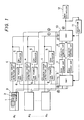
- Fig. 1 illustrates an arrangement in which a large number of HDA's indicated at symbols A1 - A n share a smaller number of access circuits and high power amplifiers
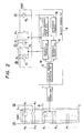
- Fig. 2 illustrates the arrangement of a velocity control circuit in Fig. 1.
- one of the HDA's will be mentioned for elucidating the position control and the velocity control.
- a servo circuit is in a position control status. Under the position control status, a position signal read by the head 1 is converted by a position error detection circuit 4 into a position error signal which expresses the positional deviation magnitude of the head from the track, and a signal is fed back to the HDA A1 so that the position error signal may become "0" at all times.
- a compensator 5 is employed for keeping the stability of a closed loop. In Fig. 1, the closed loop extends along portions 1 - 4 - 5 - 6 - 9 - 3 - 1.
- the portion 6 is a low power amplifier dedicated to the following operation
- the portion 3 is a voice coil motor.
- the portion 9 is a switch bank SW1 for changing-over the velocity control and the position control.
- the switch bank SW1 consists of n switches for the position control and n x m switches for the velocity control. Under the position control status of the HDA A1, a switch b1 in the position controlling switch group B of the switch bank SW1 is closed, whereas switches c1 corresponding to the HDA A1 in the velocity controlling switch group C of the switch bank SW1 are opened.
- numeral 2 in Fig. 1 denotes a carriage.
- the head 1 is accessed from a certain track (Tr) to a target Tr in the HDA A1.
- a selection circuit 11 an algorithm for the selection should desirably realize a random selection.
- the velocity control circuit 8 selected by the selection circuit 11 is connected with the corresponding switches of the switch bank SW1 at numeral 9 and a switch bank SW2 at numeral 10 by the signals of this selection circuit.
- the position control loop is opened. That is, the switch b1 of the position controlling switch group B of the switch bank SW1 in Fig.
- the velocity control will now be described assuming that, in the illustration of Fig. 2, the switch b1 of the position controlling switch group B of the switch bank SW1 be opened with one of the switches c1 of the velocity controlling switch group C closed, while three switches d1, d2 and d3 respectively corresponding to the signal lines D, C and E in the switch bank SW2 be closed.
- a movement track magnitude from the disk controller 12 is loaded in a difference counter 15 via the signal line E.
- a velocity error detection circuit 13 detects a velocity error on the basis of a signal from a reference velocity generator 14 corresponding to the value of the difference counter 15 and a signal from a velocity transducer 16, and a current corresponding to the velocity error is caused to flow through the coil of the voice coil motor 3 by a high power amplifier 7.
- the value of the difference counter 15 is decremented by the signal of a track-crossing pulse generator 17 each time the head 1 crosses a track.
- the velocity transducer 16 signifies an electronic tachometer which evaluates a velocity on the basis of the current flowing through the voice coil motor 3 and the differential of the position error signal. Therefore, in a case where each HDA is furnished with a mechanical tachometer, the velocity signal of this tachometer is directly applied to the velocity error detection circuit 13 instead of the current.
- the switch c1 of the velocity controlling switch group C of the switch bank SW1 and the switches d1, d2 and d3 of the switch bank SW2 are opened again, and the velocity control circuit 8 falls again into a stand-by status in which it can be connected with any desired HDA.
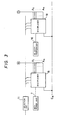
- the switch bank SW1 or SW2 is constructed of an analog multiplexer as shown in Fig. 3.
- the analog multiplexer 18 functions to select one signal from among a large number of analog signal lines.
- a signal selected by the combination of binary signals from the selection circuit 11 is delivered as the output of the multiplexer 18.
- a signal E N sets the "enable" status of the multiplexers 18.
- the present invention Since, in the present invention, the number of the velocity control circuits is smaller than that of the HDA's, the heads of all the HDA's cannot be simultaneously moved to "0" track positions at the start of the apparatus. However, the HDA's may be accessed by switching the velocity control circuits in succession, and no special consideration is required. Besides, as explained in conjunction with the embodiment, the present invention is characterized by being configured of the velocity control portions smaller in number than the actuators. Therefore, the invention is also applicable to a case where a large number of actuators are mounted on a single disk drive apparatus. In this manner, the present invention shall not be restricted as to the control setup, the number of connected units, etc.
- a plurality of velocity control circuits and power amplifiers (numbering n ) and desired l (l ⁇ n) actuators among actuators (numbering m ) in a number larger than n can be arbitrarily coupled without overlapping, and hence, up to n actuators can be simultaneously accessed, so that components can be efficiently utilized, and a disk drive apparatus or system which is inexpensive and whose installation space is small can be provided.
Landscapes
- Moving Of Head For Track Selection And Changing (AREA)
Claims (5)
- Magnetplatten-Antriebsvorrichtung mit
einer Vielzahl von Aufzeichnungsmedien,
einer Vielzahl von Köpfen (1) zum Aufzeichnen und Wiedergeben von Information auf die oder von den Aufzeichnungsmedien,
einer Vielzahl von Stellgliedern (2, 3) zum Positionieren der Köpfe (1),
einer Stellglied-Steuereinrichtung (4-8), die in eine Zugriffs-Steuereinrichtung (7,8) zum Bewegen der Köpfe (1) an eine Zielposition auf den Aufzeichnungsmedien und in eine Vielzahl von Positionssteuerschaltungen (4-6), die bewirken, daß die Köpfe (1) die Zielposition beibehalten, unterteilt ist,
einer Platten-Steuereinrichtung (12) zum Erzeugen eines die Zielposition bestimmenden Signals, und
einer Auswahleinrichtung (9, 10) zum Verbinden der Zugriffs-Steuereinrichtung (7, 8) mit einem Stellglied (2, 3) entsprechend dem Signal der Platten-Steuereinrichtung (12),
dadurch gekennzeichnet,
daß die Zugriffs-Steuereinrichtung eine Vielzahl von Zugriffs-Steuerschaltungen (7, 8) einer Anzahl, die kleiner als die Zahl der Stellglieder (2, 3) ist, aufweist, wobei die Auswahleinrichtung (9, 10) in der Lage ist, irgendeine der Zugriffs-Steuerschaltungen (7, 8) mit einem Stellglied (2, 3) zu verbinden,
daß jede der Zugriffs-Steuerschaltungen (7, 8) einen Hochleistungsverstärker (7) umfaßt, und
daß jede der Positions-Steuerschaltungen (4-6) einen Niederleistungsverstärker (6) umfaßt. - Vorrichtung nach Anspruch 1, dadurch gekennzeichnet, daß jede der Zugriffs-Steuerschaltungen (7, 8) eine Geschwindigkeits-Steuerschaltung (8) umfaßt.
- Vorrichtung nach Anspruch 1 oder 2, dadurch gekennzeichnet, daß die Zahl der Positions-Steuerschaltungen (4, 6) gleich der Zahl der Stellglieder (2, 3) ist.
- Vorrichtung nach einem der Ansprüche 1 bis 3, dadurch gekennzeichnet, daß jedes Stellglied (2, 3) einen Wagen (2), der den entsprechenden Kopf (1) radial zum Aufzeichnungsmedium bewegt, und einen Schwingspulenmotor (3), der den Wagen (2) antreibt, umfaßt.
- Verwendung der Vorrichtung nach einem der Ansprüche 1 bis 4 in einem Magnetplattengerät mit einer Vielzahl von Kopf- Platten- Baugruppen (HDA's), von denen jede ein zum magnetischen Aufzeichnen und Wiedergeben von Information geeignetes Aufzeichnungsmedium, einen Kopf (1) und ein Stellglied (2, 3) umfaßt.
Applications Claiming Priority (2)
| Application Number | Priority Date | Filing Date | Title |
|---|---|---|---|
| JP61110768A JPS62267964A (ja) | 1986-05-16 | 1986-05-16 | 磁気デイスク装置およびシステム |
| JP110768/86 | 1986-05-16 |
Publications (3)
| Publication Number | Publication Date |
|---|---|
| EP0247453A2 EP0247453A2 (de) | 1987-12-02 |
| EP0247453A3 EP0247453A3 (en) | 1989-05-24 |
| EP0247453B1 true EP0247453B1 (de) | 1993-03-10 |
Family
ID=14544088
Family Applications (1)
| Application Number | Title | Priority Date | Filing Date |
|---|---|---|---|
| EP87107026A Expired - Lifetime EP0247453B1 (de) | 1986-05-16 | 1987-05-14 | Magnetisches Plattengerät oder System |
Country Status (4)
| Country | Link |
|---|---|
| US (1) | US4851939A (de) |
| EP (1) | EP0247453B1 (de) |
| JP (1) | JPS62267964A (de) |
| DE (1) | DE3784552T2 (de) |
Families Citing this family (6)
| Publication number | Priority date | Publication date | Assignee | Title |
|---|---|---|---|---|
| CN1041357C (zh) * | 1991-05-10 | 1998-12-23 | 华中理工大学 | 时钟录写和叠写伺服码电路 |
| US6121742A (en) * | 1998-03-20 | 2000-09-19 | Seagate Technology Llc | Control scheme for multi-actuator disc drive |
| US8947816B1 (en) * | 2013-05-01 | 2015-02-03 | Western Digital Technologies, Inc. | Data storage assembly for archive cold storage |
| US9361919B1 (en) | 2014-10-10 | 2016-06-07 | Seagate Technology Llc | Disk drive with parallel head actuation |
| US9142246B1 (en) | 2014-10-10 | 2015-09-22 | Seagate Technology Llc | Apparatus and methods to reduce hard disk drive manufacturing test time |
| US10255943B1 (en) | 2018-05-17 | 2019-04-09 | Seagate Technology Llc | Independent head, dual reader control logic |
Family Cites Families (16)
| Publication number | Priority date | Publication date | Assignee | Title |
|---|---|---|---|---|
| JPS4871219A (de) * | 1971-12-27 | 1973-09-27 | ||
| JPS502565A (de) * | 1973-05-08 | 1975-01-11 | ||
| US4086636A (en) * | 1977-02-28 | 1978-04-25 | Xerox Corporation | Restore method and apparatus for disk drive |
| JPS5512528A (en) * | 1978-07-10 | 1980-01-29 | Fujitsu Ltd | Drive unit of positioner |
| JPS606790B2 (ja) * | 1978-09-29 | 1985-02-20 | 株式会社高見沢サイバネテイツクス | ナンバリングチエツクデジツト制御装置 |
| JPS563863A (en) * | 1979-06-19 | 1981-01-16 | Kyoei Zoki Kk | Brushed ice conveyor |
| US4423448A (en) * | 1979-12-26 | 1983-12-27 | Burroughs Corporation | Multi-path to data facility for disk drive transducer arms |
| JPS56145564A (en) * | 1980-04-11 | 1981-11-12 | Hitachi Ltd | Coaxial disc pack driving device |
| US4381526A (en) * | 1980-11-10 | 1983-04-26 | Memorex Corporation | Velocity control system for a data storage apparatus |
| US4407302A (en) * | 1981-04-06 | 1983-10-04 | Telectronics Pty., Ltd. | Cardiac pacemaker electrode tip structure |
| US4544968A (en) * | 1982-05-17 | 1985-10-01 | International Business Machines Corporation | Sector servo seek control |
| US4516177A (en) * | 1982-09-27 | 1985-05-07 | Quantum Corporation | Rotating rigid disk data storage device |
| US4575776A (en) * | 1982-12-20 | 1986-03-11 | International Business Machines Corporation | Magnetic recording disk file servo control system including an actuator model for generating a simulated head position error signal |
| JPS61261865A (ja) * | 1985-05-16 | 1986-11-19 | Toshiba Corp | 画像情報処理システム |
| JPS6252771A (ja) * | 1985-08-30 | 1987-03-07 | Toshiba Corp | 磁気ヘツドの速度検出装置 |
| US4669004A (en) * | 1986-02-27 | 1987-05-26 | Quantum Corporation | High capacity disk file with embedded sector servo |
-
1986
- 1986-05-16 JP JP61110768A patent/JPS62267964A/ja active Pending
-
1987
- 1987-05-11 US US07/048,587 patent/US4851939A/en not_active Expired - Fee Related
- 1987-05-14 EP EP87107026A patent/EP0247453B1/de not_active Expired - Lifetime
- 1987-05-14 DE DE87107026T patent/DE3784552T2/de not_active Expired - Fee Related
Non-Patent Citations (1)
| Title |
|---|
| PATENT ABSTRACTS OF JAPAN, vol. 4, no. 39 (P-4)(521), 28 March 1980, & JP-A-55 12528 * |
Also Published As
| Publication number | Publication date |
|---|---|
| EP0247453A3 (en) | 1989-05-24 |
| DE3784552D1 (de) | 1993-04-15 |
| JPS62267964A (ja) | 1987-11-20 |
| EP0247453A2 (de) | 1987-12-02 |
| DE3784552T2 (de) | 1993-10-14 |
| US4851939A (en) | 1989-07-25 |
Similar Documents
| Publication | Publication Date | Title |
|---|---|---|
| US3994016A (en) | Head positioning servo system for disk drives | |
| EP0428325B1 (de) | Positionierung der Lese- und Aufnahmeköpfe in einem Plattenantrieb | |
| US6735032B2 (en) | Servo write timing generation in a multi-actuator disk drive | |
| US5956201A (en) | Disk file head positioning servo system incorporating adaptive saturated seek and head offset compensation | |
| US4924160A (en) | Staggered seeking method for disk drive sector servo | |
| JPH083946B2 (ja) | サ−ボ利得補償装置 | |
| EP0247453B1 (de) | Magnetisches Plattengerät oder System | |
| US5001578A (en) | Method and system for controlling disk recording and reproduction apparatus for reduced power consumption | |
| US4616277A (en) | Disk drive storage system having means for compensating for seek driving forces coupled between head actuators | |
| EP0361381A2 (de) | Antriebsgeschwindigkeits-Steuerungssystem für die Bewegung eines Magnetkopfes in einer Platteneinheit und Platteneinheit mit diesem System | |
| US6989957B2 (en) | Disk storage device | |
| US6809895B1 (en) | Hard disk drive having a plurality of head disk assemblies | |
| EP0673033A2 (de) | Antrieb für magnetische Scheibe | |
| US6005728A (en) | Disk recording medium for embodying high capacity hard disk drive | |
| EP0130836B1 (de) | Anordnung zur Positionierungsgenauigkeit eines Zugriffarmes | |
| JPH09282818A (ja) | 磁気ディスク装置及びそれに適用するヘッド位置決め制御システム | |
| US5812339A (en) | Method and apparatus for controlling the position of an object along a radial direction of a rotating body | |
| JPH05101562A (ja) | ヘツド位置決め制御装置 | |
| JPS63142513A (ja) | 磁気デイスク装置 | |
| JPS60219680A (ja) | 磁気デイスク装置 | |
| JP2579114B2 (ja) | 磁気ディスク用ヘッド駆動方法およびその装置 | |
| JPH0192971A (ja) | 磁気ディスク装置のヘッド位置決め機構 | |
| KR950003829B1 (ko) | 디스크드라이브의 트랙억세스장치와 그 억세스방법 | |
| JPH06251492A (ja) | 磁気ディスク装置 | |
| JPS63286915A (ja) | 磁気ディスク装置の位置決め制御装置 |
Legal Events
| Date | Code | Title | Description |
|---|---|---|---|
| PUAI | Public reference made under article 153(3) epc to a published international application that has entered the european phase |
Free format text: ORIGINAL CODE: 0009012 |
|
| AK | Designated contracting states |
Kind code of ref document: A2 Designated state(s): DE FR GB |
|
| PUAL | Search report despatched |
Free format text: ORIGINAL CODE: 0009013 |
|
| AK | Designated contracting states |
Kind code of ref document: A3 Designated state(s): DE FR GB |
|
| 17P | Request for examination filed |
Effective date: 19891027 |
|
| 17Q | First examination report despatched |
Effective date: 19910312 |
|
| GRAA | (expected) grant |
Free format text: ORIGINAL CODE: 0009210 |
|
| AK | Designated contracting states |
Kind code of ref document: B1 Designated state(s): DE FR GB |
|
| REF | Corresponds to: |
Ref document number: 3784552 Country of ref document: DE Date of ref document: 19930415 |
|
| ET | Fr: translation filed | ||
| PLBE | No opposition filed within time limit |
Free format text: ORIGINAL CODE: 0009261 |
|
| STAA | Information on the status of an ep patent application or granted ep patent |
Free format text: STATUS: NO OPPOSITION FILED WITHIN TIME LIMIT |
|
| 26N | No opposition filed | ||
| PGFP | Annual fee paid to national office [announced via postgrant information from national office to epo] |
Ref country code: GB Payment date: 19960503 Year of fee payment: 10 |
|
| PGFP | Annual fee paid to national office [announced via postgrant information from national office to epo] |
Ref country code: FR Payment date: 19960520 Year of fee payment: 10 |
|
| PGFP | Annual fee paid to national office [announced via postgrant information from national office to epo] |
Ref country code: DE Payment date: 19960729 Year of fee payment: 10 |
|
| PG25 | Lapsed in a contracting state [announced via postgrant information from national office to epo] |
Ref country code: GB Effective date: 19970514 |
|
| GBPC | Gb: european patent ceased through non-payment of renewal fee |
Effective date: 19970514 |
|
| PG25 | Lapsed in a contracting state [announced via postgrant information from national office to epo] |
Ref country code: FR Free format text: LAPSE BECAUSE OF NON-PAYMENT OF DUE FEES Effective date: 19980130 |
|
| PG25 | Lapsed in a contracting state [announced via postgrant information from national office to epo] |
Ref country code: DE Free format text: LAPSE BECAUSE OF NON-PAYMENT OF DUE FEES Effective date: 19980203 |
|
| REG | Reference to a national code |
Ref country code: FR Ref legal event code: ST |