EP0247672B1 - Procédé pour mesurer la distance entre des puits contigus - Google Patents
Procédé pour mesurer la distance entre des puits contigus Download PDFInfo
- Publication number
- EP0247672B1 EP0247672B1 EP87200905A EP87200905A EP0247672B1 EP 0247672 B1 EP0247672 B1 EP 0247672B1 EP 87200905 A EP87200905 A EP 87200905A EP 87200905 A EP87200905 A EP 87200905A EP 0247672 B1 EP0247672 B1 EP 0247672B1
- Authority
- EP
- European Patent Office
- Prior art keywords
- well
- wavenumber
- distance
- magnetic field
- calculated
- Prior art date
- Legal status (The legal status is an assumption and is not a legal conclusion. Google has not performed a legal analysis and makes no representation as to the accuracy of the status listed.)
- Expired - Lifetime
Links
- 238000000034 method Methods 0.000 title claims description 28
- 230000005291 magnetic effect Effects 0.000 claims description 33
- 230000005404 monopole Effects 0.000 claims description 15
- 238000001228 spectrum Methods 0.000 claims description 15
- 238000010586 diagram Methods 0.000 claims description 10
- 230000005294 ferromagnetic effect Effects 0.000 claims description 8
- 238000005259 measurement Methods 0.000 claims description 6
- 238000013459 approach Methods 0.000 description 4
- 238000012986 modification Methods 0.000 description 2
- 230000004048 modification Effects 0.000 description 2
- 238000004458 analytical method Methods 0.000 description 1
- 230000015572 biosynthetic process Effects 0.000 description 1
- 238000012937 correction Methods 0.000 description 1
- 238000005553 drilling Methods 0.000 description 1
- 238000001914 filtration Methods 0.000 description 1
- 238000005755 formation reaction Methods 0.000 description 1
Images


Classifications
-
- G—PHYSICS
- G01—MEASURING; TESTING
- G01B—MEASURING LENGTH, THICKNESS OR SIMILAR LINEAR DIMENSIONS; MEASURING ANGLES; MEASURING AREAS; MEASURING IRREGULARITIES OF SURFACES OR CONTOURS
- G01B7/00—Measuring arrangements characterised by the use of electric or magnetic techniques
- G01B7/14—Measuring arrangements characterised by the use of electric or magnetic techniques for measuring distance or clearance between spaced objects or spaced apertures
-
- G—PHYSICS
- G01—MEASURING; TESTING
- G01V—GEOPHYSICS; GRAVITATIONAL MEASUREMENTS; DETECTING MASSES OR OBJECTS; TAGS
- G01V3/00—Electric or magnetic prospecting or detecting; Measuring magnetic field characteristics of the earth, e.g. declination, deviation
- G01V3/18—Electric or magnetic prospecting or detecting; Measuring magnetic field characteristics of the earth, e.g. declination, deviation specially adapted for well-logging
- G01V3/26—Electric or magnetic prospecting or detecting; Measuring magnetic field characteristics of the earth, e.g. declination, deviation specially adapted for well-logging operating with magnetic or electric fields produced or modified either by the surrounding earth formation or by the detecting device
Definitions
- the invention relates to a method for determining the distance between adjacent wells. More particularly it relates to a method for determining the distance between a first well in which a casing, drill string, or other ferromagnetic parts are present and a second well being drilled into subsurface earth formations adjacent said first well.
- a well being drilled it is at times desirable to know the distance between a well being drilled and a previously drilled well. For example it may be desired to drill a directional relief-well to intercept a previously drilled well in which a blow-out has occurred. On the other hand, it may also be desired that a well being drilled must avoid collision with previously drilled wells.
- US patent 3,745,446 discloses a logging method whereby the distance between a cased well and a second well is determined on the basis of magnetic logs taken in said second well.
- the logs are taken by a magnetometer assembly which is able to detect disturbances of the earth magnetic field caused by the magnetic field around the magnetic pole of a casing end in the cased well.
- a common problem is that a well may include various ferromagnetic parts which may each have separate magnetic poles. The magnetic fields of said poles may interfere at the locations where measurements are taken in the second well. In this situation it is often not possible to accurately derive the distance between the wells from magnetic logs taken in the relief well using the known techniques.
- the invention provides a reliable method for determining the distance between a first well in which ferromagnetic parts are present and a second well on the basis of magnetic logs taken in said second well, by providing an accurate indication of the distance between said wells even if said ferromagnetic parts form a complex pattern of magnetic poles, i.e. a method for determining the distance between a first well containing ferromagnetic parts and a second well having a central axis.
- This method according to the invention as set out in claim 1, comprises:
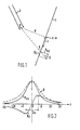
- Fig. 1 shows a sketch of a relief well passing a casing shoe in a target-well
- Fig. 2 shows the calculated axial and radial magnetic field components B z and B xy and the total field B when passing a magnetic monopole at closest distance d
- Fig. 3 shows the calculated axial and radial magnetic field components B z and B xy when passing a magnetic dipole at closest distance d
- Fig. 4 shows the magnetic disturbance B z measured in a relief-well when approaching a casing string in a target well
- Fig. 5 shows the wavenumber spectrum of the signal from Fig.
- Fig. 6A shows the theoretical wavenumber spectrum of B z (z) for a monopole with a closest distance of 3 m from a relief well
- Fig. 6B shows the theoretical wavenumber spectrum of B z (z) for a dipole with a closest distance of 3 m from a relief well.
- the method of the invention involves matching wavenumber spectra of the idealised theoretical magnetic field of a monopole or dipole with wave number spectra of features observed by means of the magnetometers located in a relief well.
- This function for the axial component B z is shown in Figure 2 together with the corresponding function for the radial component B xy and the total field
- Equivalent rules can be derived to calculate the target distance from e.g. the radial field component B xy .
- the method according to the invention for distance determination (“overlay method”), described below is less sensitive to interference and can give more accurate estimates. If interference is minimal, then this method forms an alternative to the approach described above.
- the resulting field component B z can be expressed as a convolution of the expression of one monopole or dipole and a function H(z) related to the geometry of the drillstring i.e. positions of tool joints.
- This function can be expressed as where z i is the projection of the i th pole on the relief-well track and K i is the strength of the i th pole.
- Equation (8) for a dipole is,
- the axial field component of a monopole or dipole field may be expressed as a Fourier Series of the form, "n” is called the harmonic number and "k” is a wavenumber or the reciprocal of the wavelength.
- the next step is to derive the distance to the target. This is done using an overlay technique. This technique involves attempting to find, in the amplitude/wavenumber spectrum of the field component B z , the underlying amplitude/wavenumber spectrum of a single monopole or dipole. Plotting the amplitude/wavenumber spectrum of the axial field component of a single monopole or dipole at a distance d o from a point in the relief-well, results in such signatures as seen in Figures 6A and 6B, respectively.
- a peak wavenumber k o can be determined.
- a match can be found between the single pole spectrum and the envelope of the signal spectrum which determines the peak wavenumber, k m , of the actual signal as indicated by the dashed line in Fig. 5.
- the distance from relief-well to target-well can then be found from, If the two wells are parallel to each other, the distance derived in equation (18) is a constant. However, if the wells are converging, the distance calculated represents a mean distance for the interval where the magnetic disturbance occurs.
- the contribution of the earth magnetic field to the measured data obtained by magnetometer measurements taken in the relief well can be eliminated in several ways. In some situations this contribution is only of minor importance and can be ignored. If desired, the contribution of the earth magnetic field to the measured data can be eliminated by known filtering techniques in the wavenumber domain or by subtracting said contribution from the data obtained by said magnetometer measurements before carrying out the Fourier Transform described hereinbefore. Since these correction techniques are known per se to those skilled in the art no detailed description thereof is necessary.
Landscapes
- Physics & Mathematics (AREA)
- General Physics & Mathematics (AREA)
- Remote Sensing (AREA)
- Life Sciences & Earth Sciences (AREA)
- Engineering & Computer Science (AREA)
- Environmental & Geological Engineering (AREA)
- Geology (AREA)
- Electromagnetism (AREA)
- General Life Sciences & Earth Sciences (AREA)
- Geophysics (AREA)
- Measurement Of Length, Angles, Or The Like Using Electric Or Magnetic Means (AREA)
- Measuring Magnetic Variables (AREA)
- Investigating Or Analyzing Materials By The Use Of Magnetic Means (AREA)
- Measurement And Recording Of Electrical Phenomena And Electrical Characteristics Of The Living Body (AREA)
- Geophysics And Detection Of Objects (AREA)
- Regulation And Control Of Combustion (AREA)
- Gas Burners (AREA)
Claims (5)
- Procédé pour déterminer la distance entre un premier puits (2) contenant des éléments ferromagnétiques et un second puits (1) ayant un axe central, ce procédé comprenant :
la mesure d'une caractéristique d'un champ magnétique au voisinage des éléments ferromagnétiques selon plusieurs profondeurs, et ce dans le second puits, et étant caractérisé par :
la conversion de la mesure en un signal et le tracé sur un premier graphique de l'amplitude des fréquences élémentaires du signal en fonction du nombre d'onde de celles-ci, ce nombre d'onde étant porté sur une échelle logarithmique ;
le calcul d'une caractéristique d'un champ magnétique théorique qui règne autour d'un monopôle ou d'un dipôle unique à une distance d₀ choisie par rapport à l'axe central du second puits, cette caractéristique correspondant à la caractéristique mesurée ;
le tracé sur un second graphique de l'amplitude des fréquences élémentaires de la caractéristique calculée en fonction du nombre d'onde de celles-ci, ce nombre d'onde étant porté sur une échelle logarithmique, la définition sur le second graphique d'un nombre d'onde de pic k0 qui se situe dans le spectre des nombres d'ondes dont l'amplitude a été calculée ;
la superposition des premier et second graphiques et la recherche d'un ajustement qui définisse un nombre d'onde de pic km sur le premier graphique ; et
la détermination de la distance dm entre les puits à partir de :

- Procédé selon la revendication 1, dans lequel les caractéristiques calculées et mesurées sont les composantes qui sont respectivement parallèles à l'axe central du champ magnétique théorique et du champ magnétique mesuré.
- Procédé selon la revendication 1, dans lequel les caractéristiques calculées et mesurées sont les composantes qui sont respectivement perpendiculaires à l'axe central du champ magnétique théorique et du champ magnétique mesuré.
- Procédé selon la revendication 1, dans lequel la composante axiale ainsi que les deux composantes radiales des champs magnétiques qui sont perpendiculaires l'une à l'autre sont calculées et mesurées, et dans lequel les caractéristiques calculées et mesurées sont respectivement l'amplitude du champ magnétique total théorique et du champ magnétique total mesuré.
- Procédé selon la revendication 1, dans lequel les caractéristiques calculées et mesurées sont respectivement les gradients axiaux du champ magnétique théorique et du champ magnétique mesuré ou de l'une de ses composantes.
Applications Claiming Priority (2)
| Application Number | Priority Date | Filing Date | Title |
|---|---|---|---|
| GB868613027A GB8613027D0 (en) | 1986-05-29 | 1986-05-29 | Determining distance between adjacent wells |
| GB8613027 | 1986-05-29 |
Publications (3)
| Publication Number | Publication Date |
|---|---|
| EP0247672A2 EP0247672A2 (fr) | 1987-12-02 |
| EP0247672A3 EP0247672A3 (en) | 1988-12-14 |
| EP0247672B1 true EP0247672B1 (fr) | 1991-05-08 |
Family
ID=10598609
Family Applications (1)
| Application Number | Title | Priority Date | Filing Date |
|---|---|---|---|
| EP87200905A Expired - Lifetime EP0247672B1 (fr) | 1986-05-29 | 1987-05-14 | Procédé pour mesurer la distance entre des puits contigus |
Country Status (10)
| Country | Link |
|---|---|
| EP (1) | EP0247672B1 (fr) |
| JP (1) | JPH0715235B2 (fr) |
| CA (1) | CA1269710A (fr) |
| DE (1) | DE3769848D1 (fr) |
| DK (1) | DK173097B1 (fr) |
| ES (1) | ES2022301B3 (fr) |
| GB (1) | GB8613027D0 (fr) |
| MY (1) | MY100939A (fr) |
| NO (1) | NO168438C (fr) |
| SG (1) | SG69492G (fr) |
Families Citing this family (8)
| Publication number | Priority date | Publication date | Assignee | Title |
|---|---|---|---|---|
| US5512830A (en) * | 1993-11-09 | 1996-04-30 | Vector Magnetics, Inc. | Measurement of vector components of static field perturbations for borehole location |
| MY112792A (en) * | 1994-01-13 | 2001-09-29 | Shell Int Research | Method of creating a borehole in an earth formation |
| RU2232861C1 (ru) * | 2003-02-25 | 2004-07-20 | Закрытое акционерное общество "Инженерно-производственная фирма АСУ-нефть" | Способ предупреждения встречи стволов при кустовом бурении нефтяных и газовых скважин |
| RU2235844C1 (ru) * | 2003-02-25 | 2004-09-10 | Закрытое акционерное общество "Инженерно-производственная фирма АСУ-нефть" | Система предупреждения встречи стволов при кустовом бурении нефтяных и газовых скважин |
| JP3863501B2 (ja) | 2003-05-19 | 2006-12-27 | 株式会社コナミデジタルエンタテインメント | 形態変形玩具 |
| US7475741B2 (en) * | 2004-11-30 | 2009-01-13 | General Electric Company | Method and system for precise drilling guidance of twin wells |
| RU2405106C1 (ru) * | 2009-06-18 | 2010-11-27 | Государственное образовательное учреждение высшего профессионального образования Российский государственный университет нефти и газа им. И.М. Губкина | Система контроля процесса взаимного ориентирования стволов при кустовом бурении нефтяных и газовых скважин |
| CN104919136B (zh) * | 2012-12-21 | 2018-07-10 | 哈利伯顿能源服务公司 | 使用第三井参照来执行距离测量的系统和方法 |
Family Cites Families (3)
| Publication number | Priority date | Publication date | Assignee | Title |
|---|---|---|---|---|
| US3725777A (en) * | 1971-06-07 | 1973-04-03 | Shell Oil Co | Method for determining distance and direction to a cased borehole using measurements made in an adjacent borehole |
| US4072200A (en) * | 1976-05-12 | 1978-02-07 | Morris Fred J | Surveying of subterranean magnetic bodies from an adjacent off-vertical borehole |
| US4372398A (en) * | 1980-11-04 | 1983-02-08 | Cornell Research Foundation, Inc. | Method of determining the location of a deep-well casing by magnetic field sensing |
-
1986
- 1986-05-29 GB GB868613027A patent/GB8613027D0/en active Pending
-
1987
- 1987-05-06 CA CA000536532A patent/CA1269710A/fr not_active Expired - Lifetime
- 1987-05-14 DE DE8787200905T patent/DE3769848D1/de not_active Expired - Lifetime
- 1987-05-14 ES ES87200905T patent/ES2022301B3/es not_active Expired - Lifetime
- 1987-05-14 EP EP87200905A patent/EP0247672B1/fr not_active Expired - Lifetime
- 1987-05-27 MY MYPI87000731A patent/MY100939A/en unknown
- 1987-05-27 NO NO872238A patent/NO168438C/no unknown
- 1987-05-27 JP JP62131043A patent/JPH0715235B2/ja not_active Expired - Fee Related
- 1987-05-27 DK DK198702706A patent/DK173097B1/da not_active IP Right Cessation
-
1992
- 1992-07-03 SG SG694/92A patent/SG69492G/en unknown
Also Published As
| Publication number | Publication date |
|---|---|
| NO168438C (no) | 1992-02-19 |
| NO872238D0 (no) | 1987-05-27 |
| NO872238L (no) | 1987-11-30 |
| JPH0715235B2 (ja) | 1995-02-22 |
| JPS6322987A (ja) | 1988-01-30 |
| DE3769848D1 (de) | 1991-06-13 |
| SG69492G (en) | 1992-09-04 |
| ES2022301B3 (es) | 1991-12-01 |
| GB8613027D0 (en) | 1986-07-02 |
| CA1269710A (fr) | 1990-05-29 |
| MY100939A (en) | 1991-05-31 |
| DK270687D0 (da) | 1987-05-27 |
| DK270687A (da) | 1987-11-30 |
| DK173097B1 (da) | 2000-01-17 |
| NO168438B (no) | 1991-11-11 |
| EP0247672A2 (fr) | 1987-12-02 |
| EP0247672A3 (en) | 1988-12-14 |
Similar Documents
| Publication | Publication Date | Title |
|---|---|---|
| US5512830A (en) | Measurement of vector components of static field perturbations for borehole location | |
| EP0384537B1 (fr) | Procédé pour améliorer la précision lors de la mesure de la position | |
| EP0490716B1 (fr) | Procédé et dispositif pour corriger l'effet de pendage dans un mesure d'induction d'un puits et la production d'un enregistrement correspondant à cette correction | |
| US5041975A (en) | Borehole correction system for an array induction well-logging apparatus | |
| CA2187487C (fr) | Aimant tournant pour determiner la distance et la direction | |
| EP1546980B1 (fr) | Amelioration de la resolution et correction de l'inclinaison simultanees de diagraphies de resistivite au moyen d'une deconvolution non lineaire iterative | |
| US7814036B2 (en) | Processing well logging data with neural network | |
| US7049821B2 (en) | Determination of borehole geometry inside cased wells with crosswell electromagnetics | |
| US5389881A (en) | Well logging method and apparatus involving electromagnetic wave propagation providing variable depth of investigation by combining phase angle and amplitude attenuation | |
| EP2438474B1 (fr) | Mesure magnétique de fond de trou pendant la rotation et procédé d'utilisation | |
| US4278941A (en) | High frequency induction log for determining resistivity and dielectric constant of the earth | |
| US3725777A (en) | Method for determining distance and direction to a cased borehole using measurements made in an adjacent borehole | |
| US6321456B1 (en) | Method of surveying a bore hole | |
| US20050156602A1 (en) | System, apparatus, and method for conducting electromagnetic induction surveys | |
| EP0654686A2 (fr) | Procédé pour corriger des components d'erreur axial dans les lectures magnétiques pendant les opérations de mesure dans un puits | |
| US7269514B2 (en) | System and method for correcting induction logging device measurements by alternately estimating geometry and conductivity parameters | |
| US6891777B2 (en) | Subsurface borehole evaluation and downhole tool position determination methods | |
| KR890004722B1 (ko) | 유도 탐사방법 및 장치 | |
| US6833706B2 (en) | Hole displacement measuring system and method using a magnetic field | |
| EP0247672A2 (fr) | Procédé pour mesurer la distance entre des puits contigus | |
| AU2002241657B2 (en) | Processing well logging data with neural network | |
| JPH0374350B2 (fr) | ||
| US5852363A (en) | Methods and apparatus for measuring characteristics of a formation around a borehole using computed focusing | |
| US10955579B2 (en) | Measurement and control apparatus, systems, and methods | |
| US10677955B2 (en) | Two part magnetic field gradient sensor calibration |
Legal Events
| Date | Code | Title | Description |
|---|---|---|---|
| PUAI | Public reference made under article 153(3) epc to a published international application that has entered the european phase |
Free format text: ORIGINAL CODE: 0009012 |
|
| AK | Designated contracting states |
Kind code of ref document: A2 Designated state(s): DE ES FR GB IT NL |
|
| PUAL | Search report despatched |
Free format text: ORIGINAL CODE: 0009013 |
|
| AK | Designated contracting states |
Kind code of ref document: A3 Designated state(s): DE ES FR GB IT NL |
|
| 17P | Request for examination filed |
Effective date: 19890516 |
|
| 17Q | First examination report despatched |
Effective date: 19900831 |
|
| GRAA | (expected) grant |
Free format text: ORIGINAL CODE: 0009210 |
|
| AK | Designated contracting states |
Kind code of ref document: B1 Designated state(s): DE ES FR GB IT NL |
|
| REF | Corresponds to: |
Ref document number: 3769848 Country of ref document: DE Date of ref document: 19910613 |
|
| ITF | It: translation for a ep patent filed | ||
| ET | Fr: translation filed | ||
| PLBE | No opposition filed within time limit |
Free format text: ORIGINAL CODE: 0009261 |
|
| STAA | Information on the status of an ep patent application or granted ep patent |
Free format text: STATUS: NO OPPOSITION FILED WITHIN TIME LIMIT |
|
| 26N | No opposition filed | ||
| REG | Reference to a national code |
Ref country code: GB Ref legal event code: IF02 |
|
| PGFP | Annual fee paid to national office [announced via postgrant information from national office to epo] |
Ref country code: FR Payment date: 20040309 Year of fee payment: 18 |
|
| PGFP | Annual fee paid to national office [announced via postgrant information from national office to epo] |
Ref country code: GB Payment date: 20040405 Year of fee payment: 18 |
|
| PGFP | Annual fee paid to national office [announced via postgrant information from national office to epo] |
Ref country code: ES Payment date: 20040518 Year of fee payment: 18 |
|
| PGFP | Annual fee paid to national office [announced via postgrant information from national office to epo] |
Ref country code: NL Payment date: 20040519 Year of fee payment: 18 |
|
| PGFP | Annual fee paid to national office [announced via postgrant information from national office to epo] |
Ref country code: DE Payment date: 20040602 Year of fee payment: 18 |
|
| PG25 | Lapsed in a contracting state [announced via postgrant information from national office to epo] |
Ref country code: IT Free format text: LAPSE BECAUSE OF NON-PAYMENT OF DUE FEES;WARNING: LAPSES OF ITALIAN PATENTS WITH EFFECTIVE DATE BEFORE 2007 MAY HAVE OCCURRED AT ANY TIME BEFORE 2007. THE CORRECT EFFECTIVE DATE MAY BE DIFFERENT FROM THE ONE RECORDED. Effective date: 20050514 Ref country code: GB Free format text: LAPSE BECAUSE OF NON-PAYMENT OF DUE FEES Effective date: 20050514 |
|
| PG25 | Lapsed in a contracting state [announced via postgrant information from national office to epo] |
Ref country code: ES Free format text: LAPSE BECAUSE OF NON-PAYMENT OF DUE FEES Effective date: 20050516 |
|
| PG25 | Lapsed in a contracting state [announced via postgrant information from national office to epo] |
Ref country code: NL Free format text: LAPSE BECAUSE OF NON-PAYMENT OF DUE FEES Effective date: 20051201 Ref country code: DE Free format text: LAPSE BECAUSE OF NON-PAYMENT OF DUE FEES Effective date: 20051201 |
|
| GBPC | Gb: european patent ceased through non-payment of renewal fee |
Effective date: 20050514 |
|
| PG25 | Lapsed in a contracting state [announced via postgrant information from national office to epo] |
Ref country code: FR Free format text: LAPSE BECAUSE OF NON-PAYMENT OF DUE FEES Effective date: 20060131 |
|
| NLV4 | Nl: lapsed or anulled due to non-payment of the annual fee |
Effective date: 20051201 |
|
| REG | Reference to a national code |
Ref country code: FR Ref legal event code: ST Effective date: 20060131 |
|
| REG | Reference to a national code |
Ref country code: ES Ref legal event code: FD2A Effective date: 20050516 |