EP0250975B1 - Système d'illumination - Google Patents
Système d'illumination Download PDFInfo
- Publication number
- EP0250975B1 EP0250975B1 EP87108468A EP87108468A EP0250975B1 EP 0250975 B1 EP0250975 B1 EP 0250975B1 EP 87108468 A EP87108468 A EP 87108468A EP 87108468 A EP87108468 A EP 87108468A EP 0250975 B1 EP0250975 B1 EP 0250975B1
- Authority
- EP
- European Patent Office
- Prior art keywords
- optical system
- light
- optical axis
- optical
- fresnel lens
- Prior art date
- Legal status (The legal status is an assumption and is not a legal conclusion. Google has not performed a legal analysis and makes no representation as to the accuracy of the status listed.)
- Expired - Lifetime
Links
- 238000005286 illumination Methods 0.000 title claims description 28
- 230000003287 optical effect Effects 0.000 claims description 138
- 210000001747 pupil Anatomy 0.000 claims description 21
- 239000000463 material Substances 0.000 description 6
- NAWXUBYGYWOOIX-SFHVURJKSA-N (2s)-2-[[4-[2-(2,4-diaminoquinazolin-6-yl)ethyl]benzoyl]amino]-4-methylidenepentanedioic acid Chemical compound C1=CC2=NC(N)=NC(N)=C2C=C1CCC1=CC=C(C(=O)N[C@@H](CC(=C)C(O)=O)C(O)=O)C=C1 NAWXUBYGYWOOIX-SFHVURJKSA-N 0.000 description 2
- 239000006185 dispersion Substances 0.000 description 2
- 230000010354 integration Effects 0.000 description 2
- 230000002093 peripheral effect Effects 0.000 description 2
- 230000005855 radiation Effects 0.000 description 2
- 230000004075 alteration Effects 0.000 description 1
- 230000003247 decreasing effect Effects 0.000 description 1
- 238000012986 modification Methods 0.000 description 1
- 230000004048 modification Effects 0.000 description 1
Images






Classifications
-
- G—PHYSICS
- G02—OPTICS
- G02B—OPTICAL ELEMENTS, SYSTEMS OR APPARATUS
- G02B1/00—Optical elements characterised by the material of which they are made; Optical coatings for optical elements
-
- G—PHYSICS
- G03—PHOTOGRAPHY; CINEMATOGRAPHY; ANALOGOUS TECHNIQUES USING WAVES OTHER THAN OPTICAL WAVES; ELECTROGRAPHY; HOLOGRAPHY
- G03F—PHOTOMECHANICAL PRODUCTION OF TEXTURED OR PATTERNED SURFACES, e.g. FOR PRINTING, FOR PROCESSING OF SEMICONDUCTOR DEVICES; MATERIALS THEREFOR; ORIGINALS THEREFOR; APPARATUS SPECIALLY ADAPTED THEREFOR
- G03F7/00—Photomechanical, e.g. photolithographic, production of textured or patterned surfaces, e.g. printing surfaces; Materials therefor, e.g. comprising photoresists; Apparatus specially adapted therefor
- G03F7/70—Microphotolithographic exposure; Apparatus therefor
- G03F7/70058—Mask illumination systems
- G03F7/702—Reflective illumination, i.e. reflective optical elements other than folding mirrors, e.g. extreme ultraviolet [EUV] illumination systems
-
- G—PHYSICS
- G02—OPTICS
- G02B—OPTICAL ELEMENTS, SYSTEMS OR APPARATUS
- G02B27/00—Optical systems or apparatus not provided for by any of the groups G02B1/00 - G02B26/00, G02B30/00
- G02B27/30—Collimators
Definitions
- the present invention relates to an illumination system for illuminating an object with well-collimated light according to the preamble of claim 1, as known from US-A 3,988,066.
- This conventional illumination system has a long optical path which makes an illumination apparatus incorporating such illumination systems large in size.
- the illumination system generally comprises a light source LS , an ellipsoidal mirror EM disposed with respect to the light source LS , a mirror M 1 disposed on the light path, an optical system OS , a reflection mirror M 2, a collimation system CS , a mask film MF bearing desired circuit patterns thereon and a photosensitive material PM , in order.
- the light source LS is positioned at or adjacent to the first focal point of the ellipsoidal mirror EM , so that light emmitted from the light source LS is condensed and directed to the optical system OS through the mirror M 1.
- the mirror M 1 comprises so-called a cold mirror which admits most of infrared radiation to pass therethrough and reflects most of ultraviolet radiation, thereby various disadvantageous phenomena incurred by heat can be avoided.
- the optical system OS is positioned at the point adjacent to the second focal point of the ellipsoidal mirror EM , which is the best in order to form the secondary light source by the optical system OS , since light emitted from the light source LS is most condensed at this point.
- the optical system OS is disposed at a position optically nearer to the light source LS than that as mentioned above, as far as the light directed toward the optical system OS is received within the effective area thereof.
- Light condensed by the ellipsoidal mirror EM enters into the optical system OS at the entrance height h , and in turn exits therefrom at the exit angle ⁇ , to impinge upon the incident surface of the collimation system CS .
- tan ⁇ ( H / b ) (4)
- H is an illumination height between the optical axis and the point on which the light entered at the entrance height h is impinged upon a point Q on the incident surface of the collimation system CS
- b is the distance between the incident surface of the collimation system CS and the point P at which the image of the light source LS , i.e. a secondary light source, is formed.
- the exit angle ⁇ and the illumination height H are changed when the entrance height h is increased or decreased, however the distance b can be regarded as constant because the point P is changed in such a degree as caused by the aberration, which is so small as be disregarded.
- the relationship between the radius A o around the optical axis, of the entrance pupil A , and the radius S o around it on the incident surface of the collimation system CS , within which the illumination is realized by the light entered through the radius A o, is proportional similarly to the relationship between the entrance height h and the illumination height H . That is, when the value of the radius A o is increased, the value of the radius S o is increased at the same rate. From this, it will be apparent that the irradiance distribution on the incident surface of the collimation system CS is the same as that of the entrance pupil A , from the center to the peripheral area thereof.
- FIG. 4 which shows a first example of the optical system OS , that shown therein comprises four optical units L 1 to L 4 including four lenses. Respective lens data of the optical system is listed in Table 1 .
- Fig. 5 there are shown the characteristics of the proportional constant k relative to the entrance height h when using the optical system shown in Fig. 4, where the vertical axis depicts the entrance height h , and the horizontal axis depicts the proportional constant k , which is expressed in the formula (3).
- the characteristics of the proportional constant k relative to the entrance height h show the fidelity of the optical system to the ideal optical design, from which the fact that the proportional constant k is constant independent of the entrance height h means that the optical system is designed to be ideal, i.e. the tangent of the exit angle ⁇ is exactly proportioned to the entrance height h .
- Figs. 6 through 8 show an irradiance distribution on the incident surface of the collimation system CS when using the optical system shown in Fig. 4, in which the collimation system CS is disposed at a distance of 100 from the optical system.
- Fig. 6 is a graphic representation of the irradiance distribution in the case where the point source is positioned on the optical axis at a distance of 50 from the front surface of the optical system, and Figs.
- FIG. 7 and 8 are graphic representations of the irradiance distribution of the meridional ray and the sagittal ray on the incident surface of the collimation system CS , respectively, in the case where the point source is positioned away by 14 from the optical axis and at a distance of 50 from the front surface of the optical system.
- the respective vertical axis of Figs. 6 through 8 depicts the relative irradiance when the irradiance of the center of the collimation system CS is regarded as 100 percent.
- Fig. 9 which shows a second example of the optical system OS , that shown therein comprises three optical units L 5 to L 7 including three lenses.
- the lens data of the optical system is listed in Table 2 .
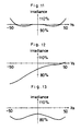
- Figs. 11 through 13 respectively, show an irradiance distribution on the incident surface of the collimation system CS when using the optical system shown in Fig. 9, in which the collimation system CS is placed at a distance of 100 from the rear surface of the optical system.
- Fig. 11 is a graphic representation of the irradiance distribution in the case where the point source is positioned on the optical axis at a distance of 50 from the front surface of the optical system.
- FIGS. 12 and 13 are graphic representations of the irradiance distribution of the meridional ray and the sagittal ray on the incident surface of the collimation system respectively, in the case where the point source is positioned away by 14 from the optical axis and at a distance of 50 from the front surface of the optical system.
- the respective vertical axis of Figs. 11 through 13 depicts the relative irradiance when the irradiance of the center of the collimation system is regarded as 100 percent.
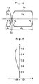
- FIG. 14 which shows a third example of the optical system OS , that shown therein comprises two optical units L 8 to L 9 including two lenses.
- the lens data of the optical system is listed in Table 3 .
- Fig. 15 there are shown the h - k characteristics of the optical system shown in Fig. 14.
- Figs. 16 through 18, respectively, show an irradiance distribution on the incident surface of the collimation system CS when using the optical system shown in Fig. 14, in which the collimation system CS is placed at a distance of 100 from the rear surface of the optical system.
- Fig. 16 is a graphic representation of the irradiance distribution in the case where the point source is positioned on the optical axis at an infinite distance from the front surface of the optical system.
- Figs. 16 is a graphic representation of the irradiance distribution in the case where the point source is positioned on the optical axis at an infinite distance from the front surface of the optical system.
- FIG. 17 and 18 are graphic representations of the irradiance distribution of the meridional ray and the sagittal ray on the incident surface of the collimation system CS respectively, in the case where the incident rays from the point source are entered into the optical system at the incident angle of 10 degrees.
- the respective vertical axis of Figs. 16 through 18 depicts the relative irradiance when the irradiance of the center of the collimation system is regarded as 100 percent.
- FIG. 19 which shows a fourth example of the optical system, that shown therein comprises a single optical unit L 10 including four lenses.
- the lens data of the optical system is listed in Table 4 .
- Fig. 20 there are shown the h - k characteristics of the optical system shown in Fig. 19.
- Figs. 21 through 23, respectively, show an irradiance distribution on the incident surface of the collimation system CS when using the optical system shown in Fig. 15, in which the collimation system is placed at a distance of 100 from the rear surface of the optical system.
- Fig. 21 is a graphic representation of the irradiance distribution in the case where the point source is positioned on the optical axis at a distance of 50 from the front surface of the optical system, and Figs.
- FIGS. 22 and 23 are graphic representations of the irradiance distribution of the meridional ray and the sagittal ray on the incident surface of the collimation system CS respectively, in the case where the point source is positioned away by 14 from the optical axis and at a distance of 50 from the front surface of the optical system.
- the respective vertical axis of Figs. 21 through 23 depicts the relative irradiance when the irradiance of the center of the collimation system is regarded as 100 percent.
- spherical lenses are used for the optical system OS , but an aspherical lens can also be used.
- the aspherical lens is designed as discussed below.
- tan ⁇ h / C (6)
- h an entrance height
- C the distance between the entrance pupil A and the point P that the real image of the light source LS is formed.
- n 1 denotes the refractive index of a prior medium to the surface of an aspherical lens
- n 2 denotes the refractive index of a posterior medium thereto
- a symbol ⁇ denotes the angle at the incident point e of the light from the infinite distance, between the normal of the surface and the optical axis
- a symbol ⁇ denotes the angle which the light refracted at the surface forms relative to the optical axis.
- the integration constant C is expressed as the following formula (17):
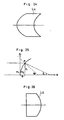
- Fig. 24 which shows a fifth example of the optical system OS , that shown therein comprises a single aspherical lens L 11.
- the aspherical lens L 11 is made of a material having a refractive index of 1.5.
- the prior medium to the lens L 11 is an air, hence the refractive index thereof is 1.0.
- the front configuration of the aspherical lens L 11 is expressed by this formula, and the shape of the rear surface thereof is designed so as to satisfy the condition that the exit light is not refracted at the rear surface.
- Fig. 26 which shows a sixth example of the optical system, that shown therein comprises a single aspherical lens L 12.
- the front surface of the aspherical lens L 12 forms a plane
- the aspherical lens L 12 is made of a material having a refractive index of 1.5.
- the rear surface thereof is designed as follows.
- the optical system shown therein comprises three optical units L 13 to L 15 including three lenses. Respective lens data of the optical system is listed in Table 5 .
- the optical system shown therein comprises four optical units L 16 to L 19 including four lenses. Respective lens data of the optical system is listed in Table 6 .
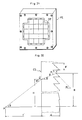
- the effective area of illumination is also rectangular, and accordingly the entrance pupil of the optical system shown in the above seventh and eighth examples is designed to be rectangular, in order to match with a specific design of the illumination system shown in this embodiment.
- the illumination system is designed so that the entrance pupil of the optical system OS is conjugated with the incident surface of the collimation system CS .
- the aforementioned optical system OS is designed as a fly-eye lens structure, in which the fly-eye lens FE includes a plurality of the optical systems as mentioned above.
- the fly-eye lens FE comprises twenty-one optical elements OE , each of which in turn comprises the optical system OS satisfying the condition that the light received in the entrance pupil has an entrance height which is substantially proportioned to the tangent of the exit angle in the exit pupil as mentioned above.
- the fly-eye lens FE is designed so that respective optical axes of optical systems thereof run in parallel to each other, whereby a plurality of rays exited therefrom are impinged on the incident surface of the collimation system CS .
- the fly-eye lens structure is very useful for resolving the irradiance non-uniformity at the entrance pupil, which enables the incident surface of the collimation system CS to be illuminated uniformly independent of the irradiance distribution at the entrance pupil.
- respective optical system of the fly-eye lens provides uniform irradiation through the entire area of the incident surface of the collimation system, thus the irradiance distribution on the incident surface of the collimation system will become very uniform.
- the illumination system is designed so that the entrance pupil of the optical system OS is conjugated with the incident surface of the collimation system CS , accordingly light passing through a predetermined common point in the entrance pupil will impinge on a predetermined common point on the incident surface of the collimation system, and consequently light emitted from the light source and received in the entrance pupil will illuminate the predetermined area of the incident surface of the collimation system, without any loss of light quantity.
- the illumination system according to the invention further comprises a reflection mirror M 2 disposed between the optical system OS and the collimation system CS .
- the reflection mirror M 2 is placed for the purpose of making the system small in size.
- the collimation system CS comprises a rectangular Fresnel lens having the focal length of 1670 mm and the diagonal length of 1000 x 1000 mm. The diagonal length thereof is determined depending on that of the mask film MF .
- the mask film MF bearing desired circuit patterns thereon has a diagonal length of 1000 x 1000 mm, and accordingly the Fresnel lens having the same diagonal length is used.
- the optical system OS is positioned so that a distance between the exit pupil of the ellipsoidal mirror EM and the entrance surface of the optical system OS is 800 mm, accordingly the secondary light source (i.e. image at the exit pupil of the ellipsoidal mirror EM ) is formed at a point within the optical system at a distance by 1 mm when using the seventh example of the optical system, and by 3 mm when using the eighth example thereof, from the exit surface thereof, and consequently the Fresnel lens CS is positioned at a distance 1670 mm, which corresponds to the focal length thereof, from the position of the secondary light source P .
- the secondary light source i.e. image at the exit pupil of the ellipsoidal mirror EM
- the configuration of the Fresnel lens is designed as follows: Referring to Fig. 32, provided that the secondary light source P is positioned on the optical axis at a distance f ⁇ from the incident surface of the Fresnel lens CS , light emitted therefrom is impinged upon a point Q which is distant from the optical axis by a distance H .
- n sin (90°- ⁇ - ⁇ ) sin (90°- ⁇ ) where ⁇ is the angle that the groove surface bearing the point T thereon forms relative to the optical axis.
- the Fresnel lens which satisfying the condition that light passing through the point T of the exit surface of the Fresnel lens runs parallel to the optical axis can be obtained by using the formulae (18) through (21).
- a first example of the Fresnel lens is adaptable for incorporating into the first through third examples of the optical system OS .
- the lens data of the Fresnel lens is listed in Table 7 .
- the distance f ⁇ between the secondary light source P and the incident surface of the Fresnel lens is 1414 mm; the focal length is also 1414 mm; lens thickness d is 5 mm; the refractive index is 1.49; groove pitch p ⁇ is 0.2 mm; and the effective aperture is 1000 mm in diagonal.
- a second example of the Fresnel lens is adaptable for incorporating into the fourth example of the optical system OS .
- the lens data of the Fresnel lens is listed in Table 8 .
- the distance f ⁇ between the secondary light source P and the incident surface of the Fresnel lens is 2020 mm; the focal length is also 2020 mm; lens thickness d is 8 mm; the refractive index is 1.52; groove pitch p ⁇ is 0.5 mm; and the effective aperture is 1000 mm in diagonal.
- a third example of the Fresnel lens is adaptable for incorporating into the seventh and eighth examples of the optical system OS .
- the lens data of the Fresnel lens is listed in Table 9 .
- the distance f ⁇ between the secondary light source P and the incident surface of the Fresnel lens is 1670 mm; the focal length is also 1670 mm; lens thickness d is 5 mm; the refractive index is 1.49; groove pitch p ⁇ is 0.05 mm; and the effective aperture is 1000 mm in diagonal.
- Figs. 28 and 30 there are respectively shown the irradiance distribution on the mask film MF when using the optical systems shown in Figs. 27 and 29, respectively.
- the x-axis and y-axis thereof respectively show the coordinate positions on the mask film MF
- the z-axis thereof shows the irradiance at the position corresponding to the coordinate position thereof. It will be apparent from Figs.
- the irradiance distribution on the mask film MF falls within the dispersion range of ⁇ 5 percent, in spite of such a wide area as 1000 x 1000 mm, which attests that the illumination system according to the invention is the most suitable for applying the well-collimated light without any irradiance reduction in the peripheral area of the mask film MF .
- the irradiance distribution on an object falls within the dispersion range of as much as ⁇ 30 percent, from which the difference between the conventional illumination systems heretofore and one according to the invention can be clearly understood.
- a photosensitive material PM is positioned immediately under the mask film MF , e.g. at a distance of 0.3 mm therebetween. Exposure of a desired circuit pattern is made accurately and effectively on the photosensitive material.
Landscapes
- Physics & Mathematics (AREA)
- General Physics & Mathematics (AREA)
- Optics & Photonics (AREA)
- Exposure And Positioning Against Photoresist Photosensitive Materials (AREA)
- Non-Portable Lighting Devices Or Systems Thereof (AREA)
- Lenses (AREA)
Claims (2)
- Système d'illumination pour illuminer un objet avec une lumière bien collimatée, comprenant dans la direction de propagation de la lumière :- une source de lumière (LS) définissant un axe optique entre la source de lumière et l'objet;- un réflecteur (EM) positionné par rapport à la source de lumière (LS) le long dudit axe optique pour diriger la lumière issue de la source de lumière (LS) le long de cet axe optique;- un système optique (OS) disposé dans ledit axe optique pour former une image (P) de la lumière reçue de la source de lumière (LS) dans l'axe optique, ce système optique (OS) comprenant une pupille d'entrée (A) recevant la lumière issue de la source de lumière (LS) et laissant passer la lumière jusqu'à une pupille de sortie; et- des moyens de collimation (CS) disposés dans ledit axe optique et recevant la lumière issue de l'image (P) formée par le système optique (OS) pour illuminer ledit objet (PM) avec de la lumière bien collimatée,
caractérisé en ce que :
ledit système optique (OS) est agencé de telle manière que la lumière entrant dans le système optique (OS) par la pupille d'entrée (A) à un emplacement à hauteur d'entrée (h) mesurée par rapport à l'axe optique est sensiblement proportionnelle à la tangente de l'angle de sortie ϑ mesuré par rapport à l'axe optique dans la pupille de sortie, et en ce que les moyens de collimation (CS) sont une lentille de Fresnel. - Système d'illumination selon la revendication 1, caractérisé en ce que la lentille de fresnel est conçue pour satisfaire aux formules :

Applications Claiming Priority (2)
| Application Number | Priority Date | Filing Date | Title |
|---|---|---|---|
| JP13847986 | 1986-06-13 | ||
| JP138479/86 | 1986-06-13 |
Publications (3)
| Publication Number | Publication Date |
|---|---|
| EP0250975A2 EP0250975A2 (fr) | 1988-01-07 |
| EP0250975A3 EP0250975A3 (en) | 1988-03-23 |
| EP0250975B1 true EP0250975B1 (fr) | 1991-08-28 |
Family
ID=15223033
Family Applications (1)
| Application Number | Title | Priority Date | Filing Date |
|---|---|---|---|
| EP87108468A Expired - Lifetime EP0250975B1 (fr) | 1986-06-13 | 1987-06-11 | Système d'illumination |
Country Status (4)
| Country | Link |
|---|---|
| US (1) | US5005959A (fr) |
| EP (1) | EP0250975B1 (fr) |
| KR (1) | KR910001504B1 (fr) |
| DE (1) | DE3772467D1 (fr) |
Families Citing this family (6)
| Publication number | Priority date | Publication date | Assignee | Title |
|---|---|---|---|---|
| EP0405563B1 (fr) * | 1989-06-29 | 1996-03-13 | Dainippon Screen Mfg. Co., Ltd. | Système d'illumination |
| DE9014406U1 (de) * | 1990-10-17 | 1990-12-20 | Kempf, Georg-Ulrich, 2057 Wentorf | Vorrichtung zum Vergrößern von transparenten Vorlagen im Durchlichtverfahren |
| US5713660A (en) * | 1993-11-10 | 1998-02-03 | Nikon Corporation | Illumination optical apparatus |
| CN103309172A (zh) * | 2013-05-30 | 2013-09-18 | 京东方科技集团股份有限公司 | 曝光设备和曝光方法 |
| JP6370626B2 (ja) * | 2014-07-24 | 2018-08-08 | オリンパス株式会社 | 照明光学系、照明装置、及び照明光学素子 |
| KR101936467B1 (ko) * | 2016-10-04 | 2019-01-11 | 인하대학교 산학협력단 | 비구면 렌즈 |
Citations (1)
| Publication number | Priority date | Publication date | Assignee | Title |
|---|---|---|---|---|
| US3988066A (en) * | 1974-01-12 | 1976-10-26 | Canon Kabushiki Kaisha | Light exposure apparatus for printing |
Family Cites Families (16)
| Publication number | Priority date | Publication date | Assignee | Title |
|---|---|---|---|---|
| US801766A (en) * | 1904-11-05 | 1905-10-10 | Corning Glass Works | Lens. |
| US1393573A (en) * | 1920-10-21 | 1921-10-11 | John A Ritter | Headlamp |
| US1986065A (en) * | 1931-12-02 | 1935-01-01 | Maillet Antoine Andre | Optical system having multiple foci and a single source of light |
| US2003804A (en) * | 1932-07-21 | 1935-06-04 | Gen Motors Corp | Lens |
| US3064125A (en) * | 1957-09-30 | 1962-11-13 | Corning Glass Works | Luminair |
| US3619023A (en) * | 1969-03-04 | 1971-11-09 | Trw Inc | Optical element for generating contour stripes |
| US3761184A (en) * | 1972-02-07 | 1973-09-25 | Itek Corp | Wide angle, narrow bandwidth laser detection system |
| US4023888A (en) * | 1975-09-12 | 1977-05-17 | Minnesota Mining And Manufacturing Company | Flashing retroreflecting device |
| DE2803277A1 (de) * | 1978-01-26 | 1979-08-02 | Bosch Gmbh Robert | Vorrichtung zur belichtung einer auf eine oberflaeche eines substrats aufgebrachten fotolackschicht |
| JPS6038681B2 (ja) * | 1978-09-27 | 1985-09-02 | キヤノン株式会社 | 紫外用多層膜 |
| US4321594A (en) * | 1979-11-01 | 1982-03-23 | American District Telegraph Company | Passive infrared detector |
| US4389115A (en) * | 1981-08-06 | 1983-06-21 | Richter Thomas A | Optical system |
| CA1191728A (fr) * | 1982-02-08 | 1985-08-13 | Marvin Waddington, Jr. | Systeme de visualisation utilisant une lentille de fresnel |
| JPS59101831A (ja) * | 1982-12-01 | 1984-06-12 | Canon Inc | 半導体焼付露光装置 |
| JPS60102737A (ja) * | 1983-11-10 | 1985-06-06 | Canon Inc | シヤツタ−装置 |
| US4770525A (en) * | 1986-03-24 | 1988-09-13 | Casio Computer Co., Ltd. | Liquid crystal projector |
-
1987
- 1987-06-11 EP EP87108468A patent/EP0250975B1/fr not_active Expired - Lifetime
- 1987-06-11 DE DE8787108468T patent/DE3772467D1/de not_active Expired - Lifetime
- 1987-06-12 KR KR1019870005975A patent/KR910001504B1/ko not_active Expired
-
1989
- 1989-05-24 US US07/357,642 patent/US5005959A/en not_active Expired - Fee Related
Patent Citations (1)
| Publication number | Priority date | Publication date | Assignee | Title |
|---|---|---|---|---|
| US3988066A (en) * | 1974-01-12 | 1976-10-26 | Canon Kabushiki Kaisha | Light exposure apparatus for printing |
Non-Patent Citations (1)
| Title |
|---|
| Naumann. H., Bauelemente der Optik, Hanser 1983 * |
Also Published As
| Publication number | Publication date |
|---|---|
| DE3772467D1 (de) | 1991-10-02 |
| KR880000804A (ko) | 1988-03-29 |
| US5005959A (en) | 1991-04-09 |
| EP0250975A2 (fr) | 1988-01-07 |
| KR910001504B1 (ko) | 1991-03-09 |
| EP0250975A3 (en) | 1988-03-23 |
Similar Documents
| Publication | Publication Date | Title |
|---|---|---|
| US4948238A (en) | Optical projection system | |
| US6181470B1 (en) | Optical element having a plurality of decentered reflecting curved surfaces, and optical instrument including the same | |
| JP3608580B2 (ja) | 照明光学装置、露光装置、露光方法、及びフライアイレンズ | |
| US20080192208A1 (en) | Projection System | |
| KR20030097784A (ko) | 마이크로리소그래피를 위한 조명 시스템 | |
| GB1475431A (en) | Exposure apparatus for printing | |
| EP0231029A2 (fr) | Système optique | |
| US6144495A (en) | Projection light source | |
| EP0587671B1 (fr) | Syteme de lentilles servant de condenseur optique pour retroprojecteur | |
| US5262819A (en) | Compact focus detecting device suitable for incorporation into an optical apparatus | |
| EP0299475B1 (fr) | Système optique pour améliorer l'intensité d'éclairage dans la zone périphérique des objets | |
| EP0250975A2 (fr) | Système d'illumination | |
| JPS62266513A (ja) | 投影露光光学系 | |
| US2604002A (en) | Optical infinity sight | |
| US20060056037A1 (en) | Projection optical system | |
| US6231198B1 (en) | Reflective optical integrator | |
| JPH0684759A (ja) | 照明装置 | |
| US6221561B1 (en) | Diffusion plate and method for manufacturing master die thereof | |
| US3758196A (en) | Optical magnifying system and apparatus for viewing small objects | |
| KR920010622B1 (ko) | 조명용 광학계 | |
| US4606606A (en) | Method and apparatus for correcting distortion and curvature of field in a display system | |
| US5402198A (en) | Focus detecting apparatus | |
| JP2720154B2 (ja) | 平行光照明用の照明装置 | |
| JPS636540A (ja) | インテグレ−タ | |
| US3226539A (en) | Bubble chamber illumination means |
Legal Events
| Date | Code | Title | Description |
|---|---|---|---|
| PUAI | Public reference made under article 153(3) epc to a published international application that has entered the european phase |
Free format text: ORIGINAL CODE: 0009012 |
|
| AK | Designated contracting states |
Kind code of ref document: A2 Designated state(s): DE FR GB IT |
|
| PUAL | Search report despatched |
Free format text: ORIGINAL CODE: 0009013 |
|
| AK | Designated contracting states |
Kind code of ref document: A3 Designated state(s): DE FR GB IT |
|
| 17P | Request for examination filed |
Effective date: 19880713 |
|
| 17Q | First examination report despatched |
Effective date: 19900806 |
|
| GRAA | (expected) grant |
Free format text: ORIGINAL CODE: 0009210 |
|
| AK | Designated contracting states |
Kind code of ref document: B1 Designated state(s): DE FR GB IT |
|
| ET | Fr: translation filed | ||
| REF | Corresponds to: |
Ref document number: 3772467 Country of ref document: DE Date of ref document: 19911002 |
|
| ITF | It: translation for a ep patent filed | ||
| PLBE | No opposition filed within time limit |
Free format text: ORIGINAL CODE: 0009261 |
|
| STAA | Information on the status of an ep patent application or granted ep patent |
Free format text: STATUS: NO OPPOSITION FILED WITHIN TIME LIMIT |
|
| 26N | No opposition filed | ||
| PGFP | Annual fee paid to national office [announced via postgrant information from national office to epo] |
Ref country code: GB Payment date: 19980602 Year of fee payment: 12 |
|
| PGFP | Annual fee paid to national office [announced via postgrant information from national office to epo] |
Ref country code: FR Payment date: 19980609 Year of fee payment: 12 |
|
| PGFP | Annual fee paid to national office [announced via postgrant information from national office to epo] |
Ref country code: DE Payment date: 19980622 Year of fee payment: 12 |
|
| PG25 | Lapsed in a contracting state [announced via postgrant information from national office to epo] |
Ref country code: GB Free format text: LAPSE BECAUSE OF NON-PAYMENT OF DUE FEES Effective date: 19990611 |
|
| PG25 | Lapsed in a contracting state [announced via postgrant information from national office to epo] |
Ref country code: FR Free format text: THE PATENT HAS BEEN ANNULLED BY A DECISION OF A NATIONAL AUTHORITY Effective date: 19990630 |
|
| GBPC | Gb: european patent ceased through non-payment of renewal fee |
Effective date: 19990611 |
|
| PG25 | Lapsed in a contracting state [announced via postgrant information from national office to epo] |
Ref country code: DE Free format text: LAPSE BECAUSE OF NON-PAYMENT OF DUE FEES Effective date: 20000503 |
|
| REG | Reference to a national code |
Ref country code: FR Ref legal event code: ST |
|
| PG25 | Lapsed in a contracting state [announced via postgrant information from national office to epo] |
Ref country code: IT Free format text: LAPSE BECAUSE OF NON-PAYMENT OF DUE FEES;WARNING: LAPSES OF ITALIAN PATENTS WITH EFFECTIVE DATE BEFORE 2007 MAY HAVE OCCURRED AT ANY TIME BEFORE 2007. THE CORRECT EFFECTIVE DATE MAY BE DIFFERENT FROM THE ONE RECORDED. Effective date: 20050611 |