EP0251015B1 - Modulunterstützungskonstruktion für vorgefertigte Sanitärinstallationen - Google Patents
Modulunterstützungskonstruktion für vorgefertigte Sanitärinstallationen Download PDFInfo
- Publication number
- EP0251015B1 EP0251015B1 EP87108601A EP87108601A EP0251015B1 EP 0251015 B1 EP0251015 B1 EP 0251015B1 EP 87108601 A EP87108601 A EP 87108601A EP 87108601 A EP87108601 A EP 87108601A EP 0251015 B1 EP0251015 B1 EP 0251015B1
- Authority
- EP
- European Patent Office
- Prior art keywords
- bars
- frame
- fixed
- supporting
- intended
- Prior art date
- Legal status (The legal status is an assumption and is not a legal conclusion. Google has not performed a legal analysis and makes no representation as to the accuracy of the status listed.)
- Expired - Lifetime
Links
- 238000009434 installation Methods 0.000 title claims abstract description 14
- 238000004519 manufacturing process Methods 0.000 description 5
- 230000004048 modification Effects 0.000 description 3
- 238000012986 modification Methods 0.000 description 3
- 239000002184 metal Substances 0.000 description 2
- 238000009417 prefabrication Methods 0.000 description 2
- 230000009466 transformation Effects 0.000 description 2
- 240000008042 Zea mays Species 0.000 description 1
- 230000006978 adaptation Effects 0.000 description 1
- 238000010276 construction Methods 0.000 description 1
- 230000001419 dependent effect Effects 0.000 description 1
- 238000005192 partition Methods 0.000 description 1
- 239000002699 waste material Substances 0.000 description 1
- XLYOFNOQVPJJNP-UHFFFAOYSA-N water Substances O XLYOFNOQVPJJNP-UHFFFAOYSA-N 0.000 description 1
Images

Classifications
-
- E—FIXED CONSTRUCTIONS
- E03—WATER SUPPLY; SEWERAGE
- E03D—WATER-CLOSETS OR URINALS WITH FLUSHING DEVICES; FLUSHING VALVES THEREFOR
- E03D11/00—Other component parts of water-closets, e.g. noise-reducing means in the flushing system, flushing pipes mounted in the bowl, seals for the bowl outlet, devices preventing overflow of the bowl contents; devices forming a water seal in the bowl after flushing, devices eliminating obstructions in the bowl outlet or preventing backflow of water and excrements from the waterpipe
- E03D11/13—Parts or details of bowls; Special adaptations of pipe joints or couplings for use with bowls, e.g. provisions in bowl construction preventing backflow of waste-water from the bowl in the flushing pipe or cistern, provisions for a secondary flushing, for noise-reducing
- E03D11/14—Means for connecting the bowl to the wall, e.g. to a wall outlet
- E03D11/143—Mounting frames for toilets and urinals
- E03D11/146—Mounting frames for toilets and urinals with incorporated cistern
Definitions
- the present invention relates to a modular support structure for prefabricated sanitary installations, comprising at least one modular frame intended to support different elements of a sanitary installation and at least two horizontal support bars fixed at the desired locations and height.
- a self-supporting framework comprising a frame formed by two horizontal crosspieces connected by uprights, the frame being supported by a base fixed to the ground.
- the modular frames are suspended on this framework.
- This type of frame allows it to be used in this way for fixing partition walls and gives a certain freedom of adaptation during installation.
- the frame has a structure (frame) which is quite rigid.
- the present invention overcomes these drawbacks by proposing a modular support structure that is easy to assemble and / or modify, even on site, without having to resort to qualified personnel or specialized factories.
- the supporting structure according to the invention is characterized in that the bars (1, 1 ') are fixed to a wall and the floor by adjustable supports (2, 2'), the supports (2 ') fixed to the floor allow to adjust the height of the lower bar (1 '), while the supports (2) fixed to the wall allow to adjust the distance from the upper bar (1) to the wall, the distance between the bars (1, 1' ) being fixed and identical to the height of the frames (4) to be supported, that each frame (4) is provided on its upper and lower sides with means (6) for fixing to the bars (1, 1 ') carrying.
- Figure 1 is a perspective view of part of the supporting structure.
- Figure 2 is a perspective view of a modular frame.
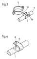
- Figure 3 is a perspective view of a means for fixing the vertical columns.
- Figure 4 is a perspective view of the means for fixing a frame on a carrier bar.
- the elements constituting a typical modular support structure are: two support bars 1 and 1 ⁇ fixed respectively to a wall and to the floor by adjustable supports 2 and 2 ⁇ , a frame 4 with its fixing means 6 to the support bars 1, 1 ⁇ and possibly fixing means 5 of the risers.
- the metal carrying bars 1, 1 ⁇ have a round or rectangular section and are arranged parallel and at a distance corresponding to the height of the frame or frames 4 which will be fixed there.
- template rods 3 are used whose length is equal to the height of a frame 4.
- the supports 2, 2 ⁇ by which the bars 1, 1 ⁇ are fixed are made, of a plate 2, 2 ⁇ provided with one or more holes to be fixed to the wall or to the floor by screws, of a threaded rod 2b, 2 ⁇ b welded to the plate 2, 2 ⁇ , of a U-shaped part 2c , 2 ⁇ c whose ends of two wings are perforated and of a bolt 2d, 2 ⁇ d.
- the threaded rod 2b, 2 ⁇ b can be provided with an interior stop piece which either is a second bolt located before the U-shaped piece 2c thus making it possible to adjust the position of the U-shaped piece 2c on the stem 2a, or it is fixed.
- an interior stop piece which either is a second bolt located before the U-shaped piece 2c thus making it possible to adjust the position of the U-shaped piece 2c on the stem 2a, or it is fixed.
- For each support bar at least two supports 2 are necessary. After having installed the loadbars 1, 1 ou the modular frame (s) 4 are hung there which support the various elements of the sanitary installation.
- the frame 4 comprises for example two crosspieces 4a, 4b, one of which is provided with rods 4c for supporting a sanitary appliance, for example a sink and the crossbeam 4b for collars or flanges 4d for fixing the flow and supply pipes in water.
- the upper and lower crosspieces of the frame 4 are provided with U-shaped pieces 6, the wings of which are perforated.
- the U-shaped parts 6 are welded by their backs to the crosspieces.
- U-shaped parts 6, during installation of the frame 4 on the bars 1, 1 ⁇ enclose or pinch between their wings the bars and the assembly is locked by driving in the holes either of keys 8 (FIG. 4) or bolts with a nut. If for any reason the frame 4 and the devices mounted on it have to be moved, simply remove the keys or bolts, remove the frame and move it to the desired position.
- FIG. 3 Another element of the installation is the means for fixing risers ( Figure 3) composed of a collar or flange 5 on which is welded a threaded rod 5a.
- a U-shaped piece 7 surrounds the support bar 1 ⁇ while the rod 5a crosses the two perforated wings of the U-shaped piece 7, the assembly being locked as for the supports 2, 2 ⁇ by at least one bolt 5b and a stop piece fixed on rod 5a or a second bolt.
Landscapes
- Health & Medical Sciences (AREA)
- Life Sciences & Earth Sciences (AREA)
- Engineering & Computer Science (AREA)
- Hydrology & Water Resources (AREA)
- Public Health (AREA)
- Water Supply & Treatment (AREA)
- Forms Removed On Construction Sites Or Auxiliary Members Thereof (AREA)
- Buffer Packaging (AREA)
- Orthopedics, Nursing, And Contraception (AREA)
- Sink And Installation For Waste Water (AREA)
- Packaging Of Machine Parts And Wound Products (AREA)
- Residential Or Office Buildings (AREA)
Claims (4)
- Modulare Tragkonstruktion für vorgefertigte sanitäre Installationen mit wenigstens einem modularen Rahmen (4), der dazu bestimmt ist, verschiedene Elemente einer sanitären Installation zu tragen, und mit wenigstens zwei horizontalen Tragstangen (1, 1'), die an den gewünschten Stellen und in gewünschter Höhe befestigt sind, dadurch gekennzeichnet, dass die Stangen (1, 1') an einer Wand und am Fussboden durch einstellbare Träger (2, 2') befestigt sind, dass die am Fussboden befestigten Träger (2') die Höhe der unteren Stange (1') einzustellen erlauben, während die an der Wand befestigten Träger (2) den Abstand der oberen Stange (1) von der Wand einzustellen erlauben, dass der Abstand zwischen den Stangen (1, 1') fest und gleich der Höhe der zu tragenden Rahmen (4) ist und dass jeder Rahmen (4) auf seinen oberen und unteren Seiten mit Mitteln (6) zur Befestigung an den Tragstangen (1, 1') versehen ist.
- Tragkonstruktion nach Anspruch 1, dadurch gekennzeichnet, dass sie ausserdem Mittel (5, 5a, 7) zur Befestigung der Steig- bzw. Fallrohre an den Tragstangen (1, 1') aufweist, bestehend aus einem Flanschring oder einer Rohrschelle (5), die fest an einem der Enden einer Gewindestange (5a) angebracht ist, während das andere Ende der Gewindestange entsprechende Oeffnungen in den Schenkeln eines U-förmigen Teils (7) durchsetzt, welcher dazu bestimmt ist, eine Tragstange (1, 1') einzuspannen oder einzuklemmen, und aus wenigstens einer Schraubenmutter (5b), welche den Zusammenbau des U-förmigen Teils (7) mit der Gewindestange (5a) gewährleistet, wodurch ein Befestigungsbügel gebildet wird.
- Tragkonstruktion nach einem der Ansprüche 1 oder 2, dadurch gekennzeichnet, dass die einstellbaren Träger (2, 2') aus einer Platte (2a, 2'a), welche zur Befestigung an einer ebenen Fläche bestimmt und an einem der Enden einer senkrecht zu dieser Platte (2, 2') orientierten Gewindestange (2b, 2'b) fest angebracht ist, und aus einem U-förmig gebogenen Teil (2c, 2'c) bestehen, dessen beide Schenkel jeweils mit einem Loch versehen sind und welcher zum Einspannen oder Einklemmen einer Tragstange (1, 1') bestimmt ist und mit der Gewindestange (2b, 2'b) einen durch wenigstens eine Schraubenmutter (2d, 2'd) blockierten Befestigungsbügel bildet.
- Tragkonstruktion nach einem der Ansprüche 1 oder 2, dadurch gekennzeichnet, dass die Mittel zur Befestigung des Rahmens (4) an den Tragstangen (1, 1') U-förmig gebogene Teile (6) aufweisen, deren Schenkel jeweils mit einem Loch versehen sind, und dass die mit ihrem U-Rücken fest am Rahmen angebrachten U-förmigen Teile zum Einspannen oder Einklemmen einer Tragstange (1, 1') bestimmt sind und zusammen mit einem die Löcher der U-Schenkel durchsetzenden Schliesskeil (8) oder Schraubenbolzen, auf dem eine Schraubenmutter sitzt, einen Befestigungsbügel bilden.
Priority Applications (1)
| Application Number | Priority Date | Filing Date | Title |
|---|---|---|---|
| AT87108601T ATE66512T1 (de) | 1986-06-27 | 1987-06-15 | Modulunterstuetzungskonstruktion fuer vorgefertigte sanitaerinstallationen. |
Applications Claiming Priority (2)
| Application Number | Priority Date | Filing Date | Title |
|---|---|---|---|
| CH2615/86 | 1986-06-27 | ||
| CH2615/86A CH668612A5 (fr) | 1986-06-27 | 1986-06-27 | Structure porteuse modulaire pour installations sanitaires prefabriquees. |
Publications (3)
| Publication Number | Publication Date |
|---|---|
| EP0251015A2 EP0251015A2 (de) | 1988-01-07 |
| EP0251015A3 EP0251015A3 (en) | 1989-03-01 |
| EP0251015B1 true EP0251015B1 (de) | 1991-08-21 |
Family
ID=4237744
Family Applications (1)
| Application Number | Title | Priority Date | Filing Date |
|---|---|---|---|
| EP87108601A Expired - Lifetime EP0251015B1 (de) | 1986-06-27 | 1987-06-15 | Modulunterstützungskonstruktion für vorgefertigte Sanitärinstallationen |
Country Status (4)
| Country | Link |
|---|---|
| EP (1) | EP0251015B1 (de) |
| AT (1) | ATE66512T1 (de) |
| CH (1) | CH668612A5 (de) |
| DE (1) | DE3772275D1 (de) |
Families Citing this family (3)
| Publication number | Priority date | Publication date | Assignee | Title |
|---|---|---|---|---|
| DE19851450A1 (de) * | 1998-11-09 | 2000-05-11 | Rost & Soehne Georg | Installationselement |
| DE20105321U1 (de) * | 2001-03-26 | 2001-06-13 | Georg Fischer Schwab GmbH & Co. KG, 72793 Pfullingen | Vorwandinstallationsvorrichtung mit Multifunktionsfuß |
| IT201800003177A1 (it) * | 2018-03-01 | 2019-09-01 | Gia S P A | Struttura di supporto di un sanitario |
Family Cites Families (4)
| Publication number | Priority date | Publication date | Assignee | Title |
|---|---|---|---|---|
| US3211454A (en) * | 1962-08-28 | 1965-10-12 | Arthur E Bailey | Vertically adjustable bowling alley section |
| FR2355962A1 (fr) * | 1976-06-23 | 1978-01-20 | Empereur Freres Sa | Procede de montage et de pose d'appareils sanitaires, les moyens de mise en oeuvre et le produit resultant du procede |
| DE2937624C2 (de) * | 1979-09-18 | 1984-05-17 | Domozell-Sanitärzellen GmbH, 5000 Köln | Installationseinrichtung für Bade-, Wasch-, Toiletten-Räume u.dgl. |
| DE3415585A1 (de) * | 1984-04-21 | 1985-10-24 | Norbert 3012 Langenhagen Ohmes | Installationswand fuer sanitaere objekte |
-
1986
- 1986-06-27 CH CH2615/86A patent/CH668612A5/fr not_active IP Right Cessation
-
1987
- 1987-06-15 AT AT87108601T patent/ATE66512T1/de not_active IP Right Cessation
- 1987-06-15 EP EP87108601A patent/EP0251015B1/de not_active Expired - Lifetime
- 1987-06-15 DE DE8787108601T patent/DE3772275D1/de not_active Expired - Lifetime
Also Published As
| Publication number | Publication date |
|---|---|
| EP0251015A2 (de) | 1988-01-07 |
| ATE66512T1 (de) | 1991-09-15 |
| DE3772275D1 (de) | 1991-09-26 |
| EP0251015A3 (en) | 1989-03-01 |
| CH668612A5 (fr) | 1989-01-13 |
Similar Documents
| Publication | Publication Date | Title |
|---|---|---|
| EP0402197A1 (de) | Vorgefertigte Schalungselemente zur Errichtung von Wänden | |
| EP1222344A1 (de) | Bewehrung für eine betonstahlwand | |
| JP5134433B2 (ja) | 配管パイプ支持用のレベルバンド | |
| FR2578564A1 (fr) | Dispositif d'attache pour le montage devant un mur d'appareils sanitaires, de robinetterie, d'elements de tuyauterie et de canalisations | |
| EP0251015A2 (de) | Modulunterstützungskonstruktion für vorgefertigte Sanitärinstallationen | |
| JPH11223281A (ja) | 配管支持用ラック | |
| JPH09194179A (ja) | ユニット吊上装置 | |
| EP0088363B1 (de) | Vorrichtung zur Aufhängung von Rohrbündeln | |
| FR2717553A1 (fr) | Dispositif réglable de suspension d'une tuyauterie. | |
| JPH1047542A (ja) | 配管用フロアバンド | |
| JPH0450352Y2 (de) | ||
| CN101147024B (zh) | 安装或移除构件时使用的临时支撑结构 | |
| KR100840279B1 (ko) | 슬래브거푸집 현수용 행거장치 | |
| JP7190134B2 (ja) | 荷受けステージ及びその取付け方法 | |
| US7832103B1 (en) | Portable jig assembly and method for use in constructing suspended strut rack systems | |
| JPH0516925U (ja) | システム天井 | |
| KR102322585B1 (ko) | 거푸집용 멍에재 | |
| JP2563586Y2 (ja) | 浴室ユニット | |
| JPH08128191A (ja) | 足場の吊下具等の止め構造 | |
| JP2772708B2 (ja) | 床パネルの配管固定構造、その配管固定方法及び配管を固定した床パネルを備えた洗面ユニット、キッチンユニット、バスユニット | |
| JPH0414561A (ja) | 建築用立管ユニットのコンクリート打設用床板の取付方法 | |
| JPH0842064A (ja) | 柱用鉄筋篭の建込方法および建込治具 | |
| JP3047743B2 (ja) | 工事用組立式足場 | |
| JP2019116787A (ja) | スラブ形成用型枠構造体、及び床スラブの構築方法 | |
| JPH077422Y2 (ja) | 設備ユニット |
Legal Events
| Date | Code | Title | Description |
|---|---|---|---|
| PUAI | Public reference made under article 153(3) epc to a published international application that has entered the european phase |
Free format text: ORIGINAL CODE: 0009012 |
|
| AK | Designated contracting states |
Kind code of ref document: A2 Designated state(s): AT DE FR |
|
| PUAL | Search report despatched |
Free format text: ORIGINAL CODE: 0009013 |
|
| AK | Designated contracting states |
Kind code of ref document: A3 Designated state(s): AT DE FR |
|
| 17P | Request for examination filed |
Effective date: 19890619 |
|
| 17Q | First examination report despatched |
Effective date: 19900706 |
|
| GRAA | (expected) grant |
Free format text: ORIGINAL CODE: 0009210 |
|
| AK | Designated contracting states |
Kind code of ref document: B1 Designated state(s): AT DE FR |
|
| REF | Corresponds to: |
Ref document number: 66512 Country of ref document: AT Date of ref document: 19910915 Kind code of ref document: T |
|
| REF | Corresponds to: |
Ref document number: 3772275 Country of ref document: DE Date of ref document: 19910926 |
|
| PG25 | Lapsed in a contracting state [announced via postgrant information from national office to epo] |
Ref country code: AT Effective date: 19920615 |
|
| PLBE | No opposition filed within time limit |
Free format text: ORIGINAL CODE: 0009261 |
|
| STAA | Information on the status of an ep patent application or granted ep patent |
Free format text: STATUS: NO OPPOSITION FILED WITHIN TIME LIMIT |
|
| 26N | No opposition filed | ||
| PG25 | Lapsed in a contracting state [announced via postgrant information from national office to epo] |
Ref country code: FR Effective date: 19930226 |
|
| PG25 | Lapsed in a contracting state [announced via postgrant information from national office to epo] |
Ref country code: DE Effective date: 19930302 |
|
| REG | Reference to a national code |
Ref country code: FR Ref legal event code: ST |