EP0251481A2 - Appareil de déverminage pour système à microprocesseur - Google Patents
Appareil de déverminage pour système à microprocesseur Download PDFInfo
- Publication number
- EP0251481A2 EP0251481A2 EP87304612A EP87304612A EP0251481A2 EP 0251481 A2 EP0251481 A2 EP 0251481A2 EP 87304612 A EP87304612 A EP 87304612A EP 87304612 A EP87304612 A EP 87304612A EP 0251481 A2 EP0251481 A2 EP 0251481A2
- Authority
- EP
- European Patent Office
- Prior art keywords
- microprocessor
- user
- rom
- mainframe
- debug tool
- Prior art date
- Legal status (The legal status is an assumption and is not a legal conclusion. Google has not performed a legal analysis and makes no representation as to the accuracy of the status listed.)
- Withdrawn
Links
Images

Classifications
-
- G—PHYSICS
- G06—COMPUTING OR CALCULATING; COUNTING
- G06F—ELECTRIC DIGITAL DATA PROCESSING
- G06F11/00—Error detection; Error correction; Monitoring
- G06F11/36—Prevention of errors by analysis, debugging or testing of software
- G06F11/362—Debugging of software
- G06F11/3648—Debugging of software using additional hardware
Definitions
- the present invention relates to digital design tools, and more particularly to a microprocessor system debug tool which controls a target microprocessor through its read only memory (ROM).
- ROM read only memory
- a logic analyzer is connected to the microprocessor bus. All input and output from the microprocessor may be decoded by the logic analyzer so that the user has a listing of the program being executed. This is a passive system.
- an emulator may be used to replace the microprocessor in developing software for the microprocessor.
- the emulator performs all the functions of the microprocessor to exercise the system, and the resulting software may then be ported into the microprocessor with the expectation that the system will function in the same manner.
- the microprocessors get more and more complicated it is geometrically more and more difficult and expensive to develop an emulator for each type of microprocessor since the emulator is unique to the particular type of microprocessor it is emulating.
- emulator is a ROM emulator where, rather than replacing the microprocessor with an emulator, a system ROM is replaced by the emulator.
- the ROM emulator interacts with the system by providing a mechanism by which the user data supplied by a ROM may be modified without requiring the user to physically reprogram and replace the ROM. It has no capabilities for stopping the microprocessor, or for providing the user with read/write operations with the system memories and registers.
- microprocessor debug tool which combines the features of the logic analyzer in decoding information from the microprocessor bus with the emulation functions of stopping the microprocessor and performing read/write operations plus the flexibility of being readily adaptable for any type of microprocessor.
- the present invention provides a microprocessor system debug tool which acts as a ROM emulator while maintaining the ability of monitoring the operation of the system.
- the debug tool communicates with a mainframe instrument via a communication module. Instructions entered by a user in the mainframe are translated into microprocessor specific code and transferred to a ROM emulator which is plugged into the system. An unused portion of the ROM is set aside by the user as an area to contain a monitor for use by the debug tool.
- a user defined control line is connected to the system's interrupt circuits which, when activated, causes the microprocessor to jump to the monitor to execute a command fragment requested by the user.
- a dedicated word recognizer monitors the microprocessor bus and reports back to the mainframe via the communication module the result of the command fragment execution.
- the microprocessor system is exercised by the ROM emulator and monitored by the word recognizer. Since only the command fragments are microprocessor specific, only relatively minor software modifications need to be made to adapt to other microprocessor types.
- a typical microprocessor system 10 has a microprocessor 12 which interconnects with other devices via a microprocessor bus 14.
- the microprocessor bus 14 includes address, data and control functions which may be in the form of a single bus with either a single word including all functions or the functions being multiplexed, or in the form of separate buses for each function.
- a ROM 16 attached to the microprocessor bus 14 generally contains nonvolatile instructions and data which the microprocessor uses in executing programs.
- a volatile random access memory (RAM) 18 is attached to the microprocessor bus 14 and contains volatile application programs and data as well as serving as a scratchpad.
- RAM random access memory
- suitable input/output (I/O) devices 20 are attached to the microprocessor bus 14 to provide communication with the surrounding environment.
- a debug tool 22 has a mainframe instrument 24 with an input device 26, such as a computer keyboard, and an output device 28, such as a CRT display, for user interface.
- a state/timing module (STM) 30 is connected to the mainframe 24 and has a processor probe 32 which is connected to the microprocessor bus 14 and a ROM connector 24 which is connected to the microprocessor bus via a ROM socket in lieu of the ROM 16.
- the STM 30 has a communications buffer 36 through which all information transfers between the mainframe and the STM 30 are processed.
- the ROM connector 34 is connected to a ROM emulator 38 which receives from the mainframe 24 via the communications buffer 36 command fragments specified by the user to be executed by the microprocessor 12.
- the processor probe 32 is connected to a dedicated word recognizer 40 which detects the result of the execution of the command fragments and forwards it to the mainframe 24 via the communications buffer 36.
- a third element, a user defined control (UDC) line 42, is connected to the interrupt system of the microprocessor 12 to alert the microprocessor when it is to stop its execution and execute the command fragments.
- the interrupt generated by the UDC may be either a manual interrupt by the user or an automatically triggered interrupt set up by the user upon the occurrence of certain events.
- the UDC may be connected to a non-maskable interrupt (NMI) of the microprocessor 12, or to a maskable interrupt. Control might also be transferred to the command fragment via execution of a branch and/or a trap instruction (SWI). Such instructions may be placed in the microprocessor program manually by the user or automatically through use of the debug tool.
- NMI non-maskable interrupt
- SWI trap instruction
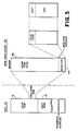
- the ROM emulator 38 is a RAM (RERAM) having a memory map as shown in Fig. 3.
- RERAM RAM
- the ROM emulator is in fact made up of a plurality of eight bit RAMs. For a sixteen bit bus two RAMs are used, each having the same addresses and size. Likewise for a thirty-two bit bus four RAMs are connected in parallel, each having the same addresses and size.
- the result to the user is an emulated ROM which may be used with any bus width without having specialized hardware for each microprocessor type.
- the user specifies a monitor portion 44 of the memory which will be used by the debug tool 22.
- the remainder 46 of the memory contains the user's code.
- the monitor portion 44 has an idle loop having a non operational (NOP) command and a branch command such as ⁇ X: Branch to X>.
- NOP non operational
- a command segment overlay is created by the mainframe 24 in response to the user's requested functions which contains the monitor code, i.e., the microprocessor specific command fragments to be executed by the target microprocessor 12.
- the command segment overlay is loaded into the monitor memory 44, replacing the idle loop with the command fragments.
- the idle loop is reloaded to return to the initial condition.
- the microprocessor system 10 operates in a normal fashion except that the monitor portion 44 of the ROM emulator 38 is not available to the microprocessor 12.
- the UDC 42 or SWI transmits an interrupt to the microprocessor 12.
- the microprocessor 12 acts upon the interrupt, the microprocessor stops its current execution and jumps to the first address of the monitor memory 44 which contains the NOP code, placing the microprocessor 12 in the idle loop.
- a flag is set to alert the mainframe 24 that the microprocessor is not executing within the monitor memory 44 and the UDC 42 is disabled.
- the user via the mainframe input device 26, asks the microprocessor 12 to execute a specific function, such as read/write to memory or registers, set/clear breakpoints or branch to user's code at ⁇ address ⁇ .
- the mainframe 24 translates the user specific function into the appropriate microprocessor specific code for execution by the type of microprocessor 12 being targeted, and the resulting command fragments are input via the command segment overlay into the monitor memory 44.
- the microprocessor 12 exits the idle loop and executes the command fragments.
- the results of the execution of the command fragments are stored in a user specified space in RAM 18 which is monitored by the word recognizer 40.
- the result is then returned to the mainframe 24 via the communications buffer 36 where it is displayed on the display device 28. Additional command fragments may be specified by the user and executed by the microprocessor 12 in the same manner.
- the microprocessor 12 is instructed to jump back to the point in the program where it was interrupted to resume regular program execution.
- the present invention provides a microprocessor debug tool which has a ROM emulator with the user's resident code and a protected monitor memory portion for command fragments specified by the user to be executed by the microprocessor upon receipt of a software interrupt or an interrupt over a user defined control line, either manual or automatic upon detection of a user specified event.
- the result of the command fragment execution is detected by a word recognizer to complete the communication loop with the user.
- the only portion of the debug tool which is microprocessor specific is that portion of the code resident in the mainframe which translates specific user requested functions into the command fragments.
Landscapes
- Engineering & Computer Science (AREA)
- Computer Hardware Design (AREA)
- Theoretical Computer Science (AREA)
- Quality & Reliability (AREA)
- Physics & Mathematics (AREA)
- General Engineering & Computer Science (AREA)
- General Physics & Mathematics (AREA)
- Debugging And Monitoring (AREA)
- Test And Diagnosis Of Digital Computers (AREA)
Applications Claiming Priority (2)
| Application Number | Priority Date | Filing Date | Title |
|---|---|---|---|
| US877625 | 1986-06-23 | ||
| US06/877,625 US4796258A (en) | 1986-06-23 | 1986-06-23 | Microprocessor system debug tool |
Publications (2)
| Publication Number | Publication Date |
|---|---|
| EP0251481A2 true EP0251481A2 (fr) | 1988-01-07 |
| EP0251481A3 EP0251481A3 (fr) | 1989-10-11 |
Family
ID=25370362
Family Applications (1)
| Application Number | Title | Priority Date | Filing Date |
|---|---|---|---|
| EP87304612A Withdrawn EP0251481A3 (fr) | 1986-06-23 | 1987-05-22 | Appareil de déverminage pour système à microprocesseur |
Country Status (6)
| Country | Link |
|---|---|
| US (1) | US4796258A (fr) |
| EP (1) | EP0251481A3 (fr) |
| JP (1) | JPS634346A (fr) |
| AU (1) | AU7458487A (fr) |
| CA (1) | CA1283486C (fr) |
| DK (1) | DK316987A (fr) |
Cited By (4)
| Publication number | Priority date | Publication date | Assignee | Title |
|---|---|---|---|---|
| EP0378242A3 (fr) * | 1989-01-13 | 1991-07-24 | Nippon Chemi-Con Corporation | Circuit intégré comportant un environnement de mise au point |
| WO1991017505A1 (fr) * | 1990-05-09 | 1991-11-14 | Applied Microsystems Corporation | Emulateur integre dans un circuit |
| EP0504515A3 (en) * | 1991-03-22 | 1993-05-26 | John Fluke Mfg. Co., Inc. | Memory emulation test system in which undesirable microprocessor reset is precluded |
| WO2014132274A1 (fr) * | 2013-02-27 | 2014-09-04 | Power-One Italy S.P.A. | Connecteur de programmation |
Families Citing this family (26)
| Publication number | Priority date | Publication date | Assignee | Title |
|---|---|---|---|---|
| US5115502A (en) * | 1984-11-02 | 1992-05-19 | Tektronix, Inc. | Method and apparatus for determining internal status of a processor using simulation guided by acquired data |
| US5025364A (en) * | 1987-06-29 | 1991-06-18 | Hewlett-Packard Company | Microprocessor emulation system with memory mapping using variable definition and addressing of memory space |
| US4914659A (en) * | 1988-02-10 | 1990-04-03 | Hewlett-Packard Company | Method and apparatus for software branch analysis |
| US4993027A (en) * | 1988-09-09 | 1991-02-12 | Pace, Incorporated | Method and apparatus for determining microprocessor kernal faults |
| JPH0278330A (ja) * | 1988-09-14 | 1990-03-19 | Marantz Japan Inc | Mca無線機用id・romエミュレータ |
| US4999837A (en) * | 1989-03-20 | 1991-03-12 | International Business Machines Corporation | Programmable channel error injection |
| JPH0362202A (ja) * | 1989-07-31 | 1991-03-18 | Japan Electron Control Syst Co Ltd | 制御プログラム開発装置 |
| US5581695A (en) * | 1990-05-09 | 1996-12-03 | Applied Microsystems Corporation | Source-level run-time software code debugging instrument |
| US5375228A (en) * | 1991-02-04 | 1994-12-20 | Analog Devices, Inc. | Real-time signal analysis apparatus and method for digital signal processor emulation |
| FR2691817B1 (fr) * | 1992-05-27 | 1997-01-31 | Sgs Thomson Microelectronics | Procede et carte electronique pour le developpement d'un circuit integre. |
| JPH06148286A (ja) * | 1992-10-31 | 1994-05-27 | Sony Corp | 回路基板装置 |
| US5497456A (en) * | 1992-12-31 | 1996-03-05 | Intel Corporation | Apparatus for transferring information between an interrupt producer and an interrupt service environment |
| US5630052A (en) * | 1993-09-30 | 1997-05-13 | Intel Corporation | System development and debug tools for power management functions in a computer system |
| US5640542A (en) * | 1993-10-29 | 1997-06-17 | Intel Corporation | On-chip in-circuit-emulator memory mapping and breakpoint register modules |
| US5537536A (en) * | 1994-06-21 | 1996-07-16 | Intel Corporation | Apparatus and method for debugging electronic components through an in-circuit emulator |
| JPH09223036A (ja) * | 1996-02-19 | 1997-08-26 | Mitsubishi Electric Corp | エミュレータ用マイクロコンピュータユニット |
| US5943391A (en) * | 1997-06-10 | 1999-08-24 | Cirrus Logic, Inc. | Method and device for a debugger and test data collector |
| US6293801B1 (en) | 1998-01-23 | 2001-09-25 | Scientific Learning Corp. | Adaptive motivation for computer-assisted training system |
| US6120298A (en) * | 1998-01-23 | 2000-09-19 | Scientific Learning Corp. | Uniform motivation for multiple computer-assisted training systems |
| US6067638A (en) * | 1998-04-22 | 2000-05-23 | Scientific Learning Corp. | Simulated play of interactive multimedia applications for error detection |
| US6113645A (en) * | 1998-04-22 | 2000-09-05 | Scientific Learning Corp. | Simulated play of interactive multimedia applications for error detection |
| US6550027B1 (en) | 2000-05-26 | 2003-04-15 | Oak Technology, Inc. | Method and article of manufacture for differentiating between a non-volatile memory device and an emulator for purposes of in-circuit programming |
| US20030212897A1 (en) * | 2001-08-18 | 2003-11-13 | Russell Dickerson | Method and system for maintaining secure semiconductor device areas |
| US7644394B2 (en) * | 2001-11-30 | 2010-01-05 | International Business Machines Corporation | Object-oriented creation breakpoints |
| US7398519B2 (en) * | 2001-11-30 | 2008-07-08 | International Business Machines Corporation | Inheritance breakpoints for use in debugging object-oriented computer programs |
| US7313729B2 (en) * | 2004-02-20 | 2007-12-25 | Winbond Electronics Corp. | Low-cost debugging system with a ROM or RAM emulator |
Family Cites Families (16)
| Publication number | Priority date | Publication date | Assignee | Title |
|---|---|---|---|---|
| JPS5239345A (en) * | 1975-09-25 | 1977-03-26 | Hitachi Ltd | General control system |
| US4315321A (en) * | 1978-06-16 | 1982-02-09 | The Kardios Systems Corporation | Method and apparatus for enhancing the capabilities of a computing system |
| US4231087A (en) * | 1978-10-18 | 1980-10-28 | Bell Telephone Laboratories, Incorporated | Microprocessor support system |
| JPS5578350A (en) * | 1978-12-08 | 1980-06-12 | Hitachi Ltd | Debug unit |
| US4312066A (en) * | 1979-12-28 | 1982-01-19 | International Business Machines Corporation | Diagnostic/debug machine architecture |
| JPS57141761A (en) * | 1981-02-25 | 1982-09-02 | Kawasaki Heavy Ind Ltd | Debugging method for microcomputer |
| JPS57146352A (en) * | 1981-03-04 | 1982-09-09 | Toshiba Corp | Debugging device |
| US4554630A (en) * | 1981-08-24 | 1985-11-19 | Genrad, Inc. | Control apparatus for back-driving computer memory and forcing execution of idle loop program in external memory |
| JPS59748A (ja) * | 1982-06-28 | 1984-01-05 | Fujitsu Ltd | 情報処理システムの保守診断方式 |
| FR2531230A1 (fr) * | 1982-07-27 | 1984-02-03 | Rank Xerox Sa | Ensemble destine au test automatique centralise de circuits imprimes et procede de test de circuits a microprocesseur faisant application de cet ensemble |
| US4569048A (en) * | 1983-09-19 | 1986-02-04 | Genrad, Inc. | Method and apparatus for memory overlay |
| US4661921A (en) * | 1984-04-23 | 1987-04-28 | Kontron Electronics, Inc. | Adapter for simultaneous use of logic analyzer and in circuit emulator |
| US4691316A (en) * | 1985-02-14 | 1987-09-01 | Support Technologies, Inc. | ROM emulator for diagnostic tester |
| US4638423A (en) * | 1985-03-06 | 1987-01-20 | Motorola, Inc. | Emulating computer |
| US4674089A (en) * | 1985-04-16 | 1987-06-16 | Intel Corporation | In-circuit emulator |
| CA1256498A (fr) * | 1986-02-19 | 1989-06-27 | Jean Auger | Appareil universel de detection de defectuosites dans des systemes a microprocesseur |
-
1986
- 1986-06-23 US US06/877,625 patent/US4796258A/en not_active Expired - Lifetime
-
1987
- 1987-05-22 EP EP87304612A patent/EP0251481A3/fr not_active Withdrawn
- 1987-05-27 CA CA000538093A patent/CA1283486C/fr not_active Expired - Lifetime
- 1987-06-22 DK DK316987A patent/DK316987A/da not_active Application Discontinuation
- 1987-06-22 JP JP62155244A patent/JPS634346A/ja active Pending
- 1987-06-22 AU AU74584/87A patent/AU7458487A/en not_active Abandoned
Non-Patent Citations (3)
| Title |
|---|
| 5TH IECI ANNUAL CONFERENCE PROCEEDINGS, INDUSTRIAL AND CONTROL APPLICATIONS OF MICROPROCESSORS, Philadelphia, 19th - 21st March 1979, pages 376-380, IEEE, New York, US; R.S. GOTTLIEB: "A microprocessor based debugging tool" * |
| BULLETIN SCIENTIFIQUE, no. 4, 95th year 1982, pages 131-136, Association des ingénieurs électriciens sortis de l'institut électrotechnique Montefiore (A.I.M.), Liège, BE; P. BALTHASART: "Development of a low cost emulator for microprocessor Z 80" * |
| ELEKTRONIK, vol. 31, no. 26, 31st December 1982, pages 51-54, Munich, DE; J. MAJEWSKI: "Universal-Emulator beschleunigt Mikrocomputerentwicklung" * |
Cited By (4)
| Publication number | Priority date | Publication date | Assignee | Title |
|---|---|---|---|---|
| EP0378242A3 (fr) * | 1989-01-13 | 1991-07-24 | Nippon Chemi-Con Corporation | Circuit intégré comportant un environnement de mise au point |
| WO1991017505A1 (fr) * | 1990-05-09 | 1991-11-14 | Applied Microsystems Corporation | Emulateur integre dans un circuit |
| EP0504515A3 (en) * | 1991-03-22 | 1993-05-26 | John Fluke Mfg. Co., Inc. | Memory emulation test system in which undesirable microprocessor reset is precluded |
| WO2014132274A1 (fr) * | 2013-02-27 | 2014-09-04 | Power-One Italy S.P.A. | Connecteur de programmation |
Also Published As
| Publication number | Publication date |
|---|---|
| DK316987D0 (da) | 1987-06-22 |
| US4796258A (en) | 1989-01-03 |
| CA1283486C (fr) | 1991-04-23 |
| JPS634346A (ja) | 1988-01-09 |
| AU7458487A (en) | 1987-12-24 |
| EP0251481A3 (fr) | 1989-10-11 |
| DK316987A (da) | 1987-12-24 |
Similar Documents
| Publication | Publication Date | Title |
|---|---|---|
| US4796258A (en) | Microprocessor system debug tool | |
| US5132971A (en) | In-circuit emulator | |
| US5615331A (en) | System and method for debugging a computing system | |
| US4819234A (en) | Operating system debugger | |
| KR970011212B1 (ko) | 데이타 프로세서 | |
| US4635193A (en) | Data processor having selective breakpoint capability with minimal overhead | |
| US5121472A (en) | Method for replacing keyboard data using single step process mode | |
| US5978902A (en) | Debug interface including operating system access of a serial/parallel debug port | |
| US6249881B1 (en) | Method for enabling and servicing critical interrupts while running an interrupt based debug monitor | |
| JPH011039A (ja) | インサーキット・エミュレータ | |
| US20020144235A1 (en) | Debugging embedded systems | |
| US5390332A (en) | Method and apparatus for performing a takeover of a microprocessor | |
| GB2281986A (en) | Logging program counter on reset. | |
| US5101342A (en) | Multiple processor data processing system with processors of varying kinds | |
| US7506205B2 (en) | Debugging system and method for use with software breakpoint | |
| EP0354654B1 (fr) | Procédé et dispositif de marquage d'états d'analyse d'émulation | |
| US6425122B1 (en) | Single stepping system and method for tightly coupled processors | |
| EP0638864B1 (fr) | Système de support de développement pour microprocesseur à antémémoire interne | |
| EP0509558B1 (fr) | Système de traitement d'information avec moyen d'assistance répondant à des commandes de système globales | |
| US5903719A (en) | Emulator apparatus and emulation method for efficiently analyzing program faults | |
| Rosenblum et al. | Simos: A fast operating system simulation environment | |
| Melear | Using background modes for testing, debugging and emulation of microcontrollers | |
| Gasser | An interactive debugger for software and firmware | |
| EP0333613A2 (fr) | Arrêt sur adresse pour mémoire microprogrammable | |
| Buechler et al. | Software error detection |
Legal Events
| Date | Code | Title | Description |
|---|---|---|---|
| PUAI | Public reference made under article 153(3) epc to a published international application that has entered the european phase |
Free format text: ORIGINAL CODE: 0009012 |
|
| AK | Designated contracting states |
Kind code of ref document: A2 Designated state(s): DE FR GB NL |
|
| RIN1 | Information on inventor provided before grant (corrected) |
Inventor name: BOYCE, DOUGLAS G. Inventor name: DELEGANES, SAM MICHAEL Inventor name: NATHANSON, ROBERT M. Inventor name: BIEBER, TIMOTHY E. |
|
| PUAL | Search report despatched |
Free format text: ORIGINAL CODE: 0009013 |
|
| AK | Designated contracting states |
Kind code of ref document: A3 Designated state(s): DE FR GB NL |
|
| 17P | Request for examination filed |
Effective date: 19900320 |
|
| 17Q | First examination report despatched |
Effective date: 19920522 |
|
| STAA | Information on the status of an ep patent application or granted ep patent |
Free format text: STATUS: THE APPLICATION IS DEEMED TO BE WITHDRAWN |
|
| 18D | Application deemed to be withdrawn |
Effective date: 19930506 |
|
| RIN1 | Information on inventor provided before grant (corrected) |
Inventor name: BIEBER, TIMOTHY E. Inventor name: DELEGANES, SAM MICHAEL Inventor name: BOYCE, DOUGLAS G. Inventor name: NATHANSON, ROBERT M. |