EP0257547A2 - Carter de volet à rouleau - Google Patents
Carter de volet à rouleau Download PDFInfo
- Publication number
- EP0257547A2 EP0257547A2 EP87112043A EP87112043A EP0257547A2 EP 0257547 A2 EP0257547 A2 EP 0257547A2 EP 87112043 A EP87112043 A EP 87112043A EP 87112043 A EP87112043 A EP 87112043A EP 0257547 A2 EP0257547 A2 EP 0257547A2
- Authority
- EP
- European Patent Office
- Prior art keywords
- roller shutter
- shutter box
- inspection cover
- wall
- closure part
- Prior art date
- Legal status (The legal status is an assumption and is not a legal conclusion. Google has not performed a legal analysis and makes no representation as to the accuracy of the status listed.)
- Withdrawn
Links
Images


Classifications
-
- E—FIXED CONSTRUCTIONS
- E06—DOORS, WINDOWS, SHUTTERS, OR ROLLER BLINDS IN GENERAL; LADDERS
- E06B—FIXED OR MOVABLE CLOSURES FOR OPENINGS IN BUILDINGS, VEHICLES, FENCES OR LIKE ENCLOSURES IN GENERAL, e.g. DOORS, WINDOWS, BLINDS, GATES
- E06B9/00—Screening or protective devices for wall or similar openings, with or without operating or securing mechanisms; Closures of similar construction
- E06B9/02—Shutters, movable grilles, or other safety closing devices, e.g. against burglary
- E06B9/08—Roll-type closures
- E06B9/11—Roller shutters
- E06B9/17—Parts or details of roller shutters, e.g. suspension devices, shutter boxes, wicket doors, ventilation openings
- E06B9/17007—Shutter boxes; Details or component parts thereof
- E06B9/17023—Shutter boxes; Details or component parts thereof made of more than two pieces
-
- E—FIXED CONSTRUCTIONS
- E06—DOORS, WINDOWS, SHUTTERS, OR ROLLER BLINDS IN GENERAL; LADDERS
- E06B—FIXED OR MOVABLE CLOSURES FOR OPENINGS IN BUILDINGS, VEHICLES, FENCES OR LIKE ENCLOSURES IN GENERAL, e.g. DOORS, WINDOWS, BLINDS, GATES
- E06B9/00—Screening or protective devices for wall or similar openings, with or without operating or securing mechanisms; Closures of similar construction
- E06B9/02—Shutters, movable grilles, or other safety closing devices, e.g. against burglary
- E06B9/08—Roll-type closures
- E06B9/11—Roller shutters
- E06B9/17—Parts or details of roller shutters, e.g. suspension devices, shutter boxes, wicket doors, ventilation openings
- E06B2009/17069—Insulation
Definitions
- the innovation relates to a roller shutter box according to the preamble of claim 1.
- roller shutter boxes have recently been offered for direct connection to the top of a window or door frame with the indication that the assembly and maintenance of the roller shutter which can be wound inside the box body is possible from the outside.
- Roller shutter boxes of the type in question are thus characterized by the lack of an inner mounting cover and by excellent heat and sound insulation. Due to the fact that an inner mounting cover is missing, wallpaper or plaster damage can be avoided during maintenance of the roller shutter or roller shutter drive with access to the rolling space arranged inside the box body
- a disadvantage of the known constructions of the type mentioned is the assembly and disassembly of the outer inspection cover, which is conventionally fastened to the outer front side of the window frame by means of a plurality of screws or the like. Of course, this also means a corresponding adjustment of the window frame to the roller shutter box to be assembled or vice versa.
- the roller shutter box is therefore not a self-contained unit.
- the present innovation is therefore based on the object of improving a roller shutter box of the type mentioned in such a way that easier assembly and disassembly of the outer inspection cover is possible with the formation of a self-contained structural unit.
- This object is achieved in a surprisingly simple manner in that the inspection cover can be attached directly to the lower closure part of the box body, by means of a releasable latching connection.
- the inspection cover can be fastened to the lower closure part of the box body
- the inspection cover is a component which belongs directly to the roller shutter box.
- the roller shutter box, including the inspection cover is a self-contained unit that is assigned to a window or door frame as a whole without intervention in it.
- the snap-in connection provided according to the invention enables extremely easy assembly and disassembly of the inspection cover, even by laypersons, ie. H. User of the roller shutter box according to the invention or innovation.
- an inspection cover designed in this way is relatively light; on the other hand, it promotes sound and heat insulation at the same time. It serves as a sound and heat barrier, which additionally increases the sound and heat insulation of the entire roller shutter box.
- the inspection cover which is designed as a hollow profile body, can still be foamed, in particular with the polystyrene rigid foam already used to form the box body.
- other insulating materials such as mineral wool, rock wool, or the like are also conceivable.
- this also applies to the box body. Then of course this must be formed with an outer and inner shell, since mineral wool or the like is not self-supporting in contrast to the proposed hard foam.
- the locking means namely locking projection and locking receptacle
- the inspection cover is made of plastic, preferably extruded plastic, for reasons of manufacture and weight, among other things.
- roller shutter guide rails are fastened to the masonry by means of concealed, adjustable, rustproof fastening angles, preferably made of aluminum.
- the mounting brackets are plastered in a cavity-like rear chamber of the track. This is removable.
- the rail closes flush with the Plastering off.
- the same rail is fastened back to back with adjustable aluminum extension hooks on the window or door frame.
- the roller shutter box 10 shown in FIG. 1 comprises a box body 12 made of rigid polystyrene foam, which is approximately U-shaped in cross section and delimits a roller shutter receiving space or rolling space 11, the legs of which define the outer wall 13 and inner wall 14 on the outer sides each with a Plaster base serving lightweight board 15, 16 are clad.
- a roller shutter 17 can be wound up and unwound in a conventional manner within the roll space 11.
- the winding axis is identified in FIG. 1 by the reference number 18.
- the lightweight panels 15, 16 consist of cement-bound wood wool and are foamed on the corresponding outer sides of the box body.
- the box body 12 formed in this way is reinforced by means of a rib steel fabric 19, the rib steel fabric 19 being partially exposed in the upper region of the box body, with the formation of a lintel anchoring 20.
- the rib steel fabric is preferred as formed from ribbed steel rods with a diameter of about 4 mm.
- the box body described is usually provided as a body about 6 m long. Specialist dealers then manufacture from this 6-meter element dimensionally accurate roller shutter boxes, the end faces of which are veneered with appropriate closure of the roll room 11 before assembly, for. B. by means of appropriately cut chipboard panels or the like.
- the outer wall 13 and the inner wall 14 of the box body 12 each align approximately with the outside or inside of a building wall into which the roller shutter box described above is inserted above a window or door frame 25.
- the window or door assigned to the window or door frame 25 is identified in FIG. 1 by the reference number 26.
- the inspection cover 22 is thus attached directly to the closure part 21, which is also made of rigid polystyrene foam and on the outside facing the interior of the building or the like, similar to the outside of the inner wall 14 of the box body 12 with a lightweight board 27 made of cement-bound wood wool serving as a plaster base is disguised. Effective sound and heat insulation is also achieved in the inner corner region of the roller shutter box 10 by the closure part 21 designed in this way, which extends over the entire length of the box body 12.
- the Ver The closing part 21 is fastened to the inner wall 14 of the box body 12 before the assembly of the roller shutter box 10, preferably permanently attached, in particular glued.
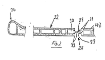
- the inspection cover 22 is detachably fastened to the closure part 21 by means of a latching connection 28.
- the latching connection is formed by a latching projection 29 which is arranged on the closure part 21 and extends over the entire length thereof, and a latching receptacle 30 of complementary design on the inspection cover 22. It is a kind of tongue and groove connection between the inspection cover 22 and the closure part 21.
- the locking projection 29 has an arrow-like cross section with undercuts 31 which are engaged behind by corresponding projections 32 of the locking receptacle 30.
- the flanks 33 of the arrow-like locking projection 29 can be curved slightly convexly to make it easier to snap the locking connection 28 in and out.
- flanks delimiting the undercuts 31 are preferably slightly forwards, i. H. inclined towards the arrowhead.
- the detent connection 28 can be loosened when the inspection cover 22 is removed by tilting it downward about the detent connection 28 without great effort.
- the locking connection can be made very easily again.
- the described design of the locking projection 29 is quite significant measures which considerably facilitate the assembly and disassembly of the inspection cover 22.
- the locking projection 29 and the complementary locking receptacle 30 extend approximately parallel to the flat side of the inspection cover 22. In principle, it would also be conceivable to design the locking projection 29 facing downward. The latching receptacle 30 should then be open at the top. It is also conceivable that Attach locking projection 29 on the inspection cover 22 and the locking receptacle 30 on the closure part 21.
- the inspection cover 22 has on its side facing the roller shutter exit slot 23 a bead serving as a rolling cross member, namely a sliding bead 34.
- the inspection cover 22 is securely held in its predetermined position even under heavy loads, in particular by the up and down moving roller shutters 17, the inspection cover is additionally assigned holding brackets (not shown) on the face side, on the underside of which the inspection cover 22 is penetrated by screws that penetrate the inspection cover or the like. Can be connected. These screws must of course be loosened before removing the inspection cover 22. The assembly or disassembly of the inspection cover is only insignificantly difficult.
- the associated guide rails 35 are the associated guide rails 35, as shown in FIG. 3, in association with the window or door frame 25.
- the guide rail 35 shown is H - Profile trained.
- a cavity 38 which is closed on all sides and into which a leg 39 of a fastening bracket 40 arranged under plaster can be inserted can be formed by connecting it to the masonry 36 or the plaster 37 thereof.
- the mounting bracket 40 is not visible from the outside.
- Mounting bracket 40 and guide rail 35 are preferably made of aluminum.
- the actual running rail 41 is provided on the inside in a conventional manner with rubber baits or brush seals 42.
- the mounting bracket 40 of which more or less must be provided depending on the length of the guide rail 35, are on the wall 36 by means of an adjusting screw be 43 attached in such a way that the distance between the mounting bracket of the wall 36 is adjustable.
- the leg 44 of the fastening bracket 40 which can be connected to the wall 36 has an elongated hole (not shown) which extends in the direction of its longitudinal extent and through which the adjusting screw 43 is passed. In this way, the distance of the guide rail 35 from the window or door frame 25 can be adjusted precisely.
- the leg 39 of the mounting bracket 40 to be connected to the guide rail 35 or protruding from the masonry 36 can have an elongated hole (likewise not shown) which extends in the longitudinal extent of this leg 39 and through which a rail fastening screw 45 can be passed.
- the guide rail 35 is also adjustable in the direction approximately perpendicular to the wall 36 in such a way that it always ends flush with the plaster 37.
- the adjoining surfaces of the guide rail 35 and the fastening bracket 40 each have a rib profile 46 which extends in the direction of the longitudinal extent of the guide rail 35. This simplifies the assembly of the guide rail 35.
- the rubber baits 42 can of course also be replaced by conventional brush tapes, which also have a noise-dampening effect.
- the inspection cover is outside the window 26, but within the reveal.
- the inspection cover 22 consists of weatherproof, highly resistant PVC material. It can be produced as an extruded profile in the manner shown.
- roller shutter box described is suitable for 24/30/36 masonry. A wall offset does not have to be accepted.
- the locking projection 29 is an integral part of a profile body 47 fastened to the underside of the closure part 21, the underside of which is connected to the underside of the closure part 21 or to the underside of the lightweight building board 27 is flush.
- the profile body 7 is glued to the underside of the closure part 21 and at the same time forms the support surface for the roller shutter box on the window or door frame 25.
- the width of the profile body 47 is somewhat less than the width of the window or door frame 25 in order to avoid that a cold bridge arises through the profile body 47.
- the fact that the profile body 47 is designed as a hollow profile body, it is itself good heat and sound insulation.
- roller shutter box 10 described is preferably attached to the window or door frame via the hollow profile body 47 such that cold air penetration into the interior between the roller shutter box 10 and window or door frame 25 is reliably avoided.
- an additional seal can be provided between the roller shutter box 10 and the top of the window or door frame 25.
- closure part 21 can also be an integral part of the roller shutter box 12. Basically, it is also conceivable that with appropriate positioning of the shutter box relative to the window or.
- Door frame 25 of the outer inspection cover 22 can be connected directly to the inner wall 14 of the box body 12 in the manner described above.
Landscapes
- Engineering & Computer Science (AREA)
- Structural Engineering (AREA)
- Architecture (AREA)
- Civil Engineering (AREA)
- Operating, Guiding And Securing Of Roll- Type Closing Members (AREA)
- Building Environments (AREA)
- Tents Or Canopies (AREA)
Applications Claiming Priority (2)
| Application Number | Priority Date | Filing Date | Title |
|---|---|---|---|
| DE3628238 | 1986-08-20 | ||
| DE19863628238 DE3628238A1 (de) | 1986-08-20 | 1986-08-20 | Rolladenkasten |
Publications (2)
| Publication Number | Publication Date |
|---|---|
| EP0257547A2 true EP0257547A2 (fr) | 1988-03-02 |
| EP0257547A3 EP0257547A3 (fr) | 1989-04-12 |
Family
ID=6307781
Family Applications (1)
| Application Number | Title | Priority Date | Filing Date |
|---|---|---|---|
| EP87112043A Withdrawn EP0257547A3 (fr) | 1986-08-20 | 1987-08-19 | Carter de volet à rouleau |
Country Status (2)
| Country | Link |
|---|---|
| EP (1) | EP0257547A3 (fr) |
| DE (1) | DE3628238A1 (fr) |
Cited By (3)
| Publication number | Priority date | Publication date | Assignee | Title |
|---|---|---|---|---|
| GB2242923A (en) * | 1990-03-12 | 1991-10-16 | Kedzia Krystyna Irena | Roller-shutter housing assembly |
| EP0740045A3 (fr) * | 1995-04-28 | 1998-04-08 | Johann Henkenjohann | Caisson pour volet roulant |
| GB2351753A (en) * | 1999-04-22 | 2001-01-10 | Isotra S R O | A carrier for a blind mechanism |
Families Citing this family (6)
| Publication number | Priority date | Publication date | Assignee | Title |
|---|---|---|---|---|
| DE3725606C2 (de) * | 1987-08-01 | 1996-05-15 | Helmut Lehr | Rolladenkasten sowie Verfahren zu seiner Herstellung |
| DE19908571C2 (de) * | 1999-02-27 | 2002-01-17 | Sks Stakusit Bautechnik Gmbh | Rolladenaggregat |
| DE10101910A1 (de) * | 2001-01-16 | 2002-07-18 | Helmut Lehr Rolladenkasten | Rollladenkasten |
| DE10326015A1 (de) * | 2003-05-29 | 2004-12-30 | Saint-Gobain Weber Gmbh | Gebäudewandkonstruktion mit Rollladenkasten mit Wärmedämmplatten |
| EP2325433A2 (fr) | 2009-11-20 | 2011-05-25 | Alltec GmbH | Caisse de réception d'un obscurcissement pour une fenêtre ou une porte ainsi que procédé de fabrication d'une telle caisse |
| DE202019002886U1 (de) * | 2019-07-05 | 2020-09-04 | Hans-Peter Häusel | Rollladenkasten-Dämmsystem für Rollläden die in der Mauer installiert sind |
Family Cites Families (5)
| Publication number | Priority date | Publication date | Assignee | Title |
|---|---|---|---|---|
| DE1977983U (de) * | 1967-11-04 | 1968-02-01 | Kubi Jalousie G M B H & Co K G | Zweiteiliges rolladen-seitenfuehrungsprofil mit schwenk- und verstellbereich. |
| DE2004668A1 (de) * | 1970-02-03 | 1971-08-12 | Schmitz, Josef, 4050 Monchenglad bach | Seitliche Fuhrung fur Rolladen |
| DE3129994A1 (de) * | 1981-07-29 | 1983-03-03 | Karl Bachl Ziegel- und Betonwerke, 8391 Deching | Rolladenkasten sowie verfahren zu seiner herstellung |
| DE8613285U1 (de) * | 1986-05-16 | 1986-07-03 | Staudt, Erwin, 8751 Sulzbach | Rolladenfensterelement |
| DE8622304U1 (de) * | 1986-08-20 | 1986-10-02 | Bohn, Alfred, 6927 Bad Rappenau | Rolladenkasten |
-
1986
- 1986-08-20 DE DE19863628238 patent/DE3628238A1/de not_active Withdrawn
-
1987
- 1987-08-19 EP EP87112043A patent/EP0257547A3/fr not_active Withdrawn
Cited By (5)
| Publication number | Priority date | Publication date | Assignee | Title |
|---|---|---|---|---|
| GB2242923A (en) * | 1990-03-12 | 1991-10-16 | Kedzia Krystyna Irena | Roller-shutter housing assembly |
| GB2242923B (en) * | 1990-03-12 | 1993-12-01 | Kedzia Krystyna Irena | Roller-shutter assembly |
| EP0740045A3 (fr) * | 1995-04-28 | 1998-04-08 | Johann Henkenjohann | Caisson pour volet roulant |
| GB2351753A (en) * | 1999-04-22 | 2001-01-10 | Isotra S R O | A carrier for a blind mechanism |
| GB2351753B (en) * | 1999-04-22 | 2003-02-12 | Isotra S R O | Profiled carrier for the reception of a driving mechanism for controlling of louvres |
Also Published As
| Publication number | Publication date |
|---|---|
| EP0257547A3 (fr) | 1989-04-12 |
| DE3628238A1 (de) | 1988-03-10 |
Similar Documents
| Publication | Publication Date | Title |
|---|---|---|
| EP0932742B1 (fr) | Element de porte ou de fenetre | |
| EP0257547A2 (fr) | Carter de volet à rouleau | |
| DE8622304U1 (de) | Rolladenkasten | |
| EP0918127B1 (fr) | Châssis de porte et dispositif de montage | |
| DE9313426U1 (de) | Lüftungsvorrichtung für Räume | |
| DE3800446C2 (de) | Profilleiste für die Errichtung von Trennwänden u.dgl., insbesondere für Dusch- oder Badewannenabtrennungen | |
| DE10361123B4 (de) | Verlorene Schalung zur Aufnahme eines Rollladens oder einer Jalousie | |
| AT394419B (de) | Rolladenkasten | |
| DE3202833A1 (de) | Verkleidung fuer eine in einem bauwerk befestigte zarge fuer eine zimmer- oder haustuere oder dgl. | |
| DE68902335T2 (de) | Aus plastikrahmen, befestigungsmitteln sowie abdichtungsmitteln bestehender rahmensatz. | |
| DE102019122600A1 (de) | Vorsatzschalenanordnung für ein Verbundfenster sowie Verbundfenstersystem aufweisend die Vorsatzschalenanordnung | |
| EP1041236A2 (fr) | Carter de volet à rouleau | |
| DE2125272A1 (de) | Einbaufertige Schiebetüranordnung | |
| DE19618837C1 (de) | Befestigungsvorrichtung für Laibungsplatten an Fenster- und Türstöcken | |
| DE8218308U1 (de) | Rolladenkasten | |
| DE6934397U (de) | Waermeisolierter tuer- oder decklartiger verschluss fuer kuehlmoebel. | |
| DE2064538A1 (de) | Einbauwand | |
| CH510194A (de) | Einbautür | |
| DE7414512U (de) | Vorrichtung zur Festlegung von Türzargen und dergleichen | |
| DE2302291A1 (de) | Fertigelement fuer den einbau in wanddurchbrueche | |
| DE20023502U1 (de) | Rollladenkasten | |
| DE7903407U1 (de) | Laengsfuehrungsschiene fuer rollaeden | |
| DE1994496U (de) | Rolladenkasten. | |
| EP0902149A2 (fr) | Porte coulissante pour murs en construction à sec | |
| DE7827131U1 (de) | Laengsfuehrungsschiene fuer rollaeden |
Legal Events
| Date | Code | Title | Description |
|---|---|---|---|
| PUAI | Public reference made under article 153(3) epc to a published international application that has entered the european phase |
Free format text: ORIGINAL CODE: 0009012 |
|
| AK | Designated contracting states |
Kind code of ref document: A2 Designated state(s): AT BE CH DE FR LI NL |
|
| PUAL | Search report despatched |
Free format text: ORIGINAL CODE: 0009013 |
|
| AK | Designated contracting states |
Kind code of ref document: A3 Designated state(s): AT BE CH DE FR LI NL |
|
| 17P | Request for examination filed |
Effective date: 19890518 |
|
| 17Q | First examination report despatched |
Effective date: 19891227 |
|
| STAA | Information on the status of an ep patent application or granted ep patent |
Free format text: STATUS: THE APPLICATION IS DEEMED TO BE WITHDRAWN |
|
| 18D | Application deemed to be withdrawn |
Effective date: 19910503 |
|
| RIN1 | Information on inventor provided before grant (corrected) |
Inventor name: BOHN, ALFRED |