EP0257662A2 - Méthode pour commander automatiquement un véhicule - Google Patents
Méthode pour commander automatiquement un véhicule Download PDFInfo
- Publication number
- EP0257662A2 EP0257662A2 EP87114703A EP87114703A EP0257662A2 EP 0257662 A2 EP0257662 A2 EP 0257662A2 EP 87114703 A EP87114703 A EP 87114703A EP 87114703 A EP87114703 A EP 87114703A EP 0257662 A2 EP0257662 A2 EP 0257662A2
- Authority
- EP
- European Patent Office
- Prior art keywords
- running
- vehicle
- speed
- standard
- target
- Prior art date
- Legal status (The legal status is an assumption and is not a legal conclusion. Google has not performed a legal analysis and makes no representation as to the accuracy of the status listed.)
- Granted
Links
- 238000000034 method Methods 0.000 title claims abstract description 19
- 238000005381 potential energy Methods 0.000 claims description 11
- 230000003247 decreasing effect Effects 0.000 claims description 3
- 239000003550 marker Substances 0.000 description 22
- 238000010586 diagram Methods 0.000 description 5
- 230000008569 process Effects 0.000 description 4
- 102000051759 human factor J Human genes 0.000 description 3
- 108700008420 human factor J Proteins 0.000 description 3
- 238000007796 conventional method Methods 0.000 description 2
- 238000001514 detection method Methods 0.000 description 2
- 238000012545 processing Methods 0.000 description 2
- 238000005070 sampling Methods 0.000 description 2
- 230000001133 acceleration Effects 0.000 description 1
- 230000004075 alteration Effects 0.000 description 1
- 230000001174 ascending effect Effects 0.000 description 1
- 238000004364 calculation method Methods 0.000 description 1
- 238000004891 communication Methods 0.000 description 1
- 230000000694 effects Effects 0.000 description 1
- 238000002474 experimental method Methods 0.000 description 1
- 230000009467 reduction Effects 0.000 description 1
- 230000004044 response Effects 0.000 description 1
- 238000004088 simulation Methods 0.000 description 1
Images




Classifications
-
- B—PERFORMING OPERATIONS; TRANSPORTING
- B61—RAILWAYS
- B61L—GUIDING RAILWAY TRAFFIC; ENSURING THE SAFETY OF RAILWAY TRAFFIC
- B61L15/00—Indicators provided on the vehicle or train for signalling purposes
- B61L15/0062—On-board target speed calculation or supervision
-
- Y—GENERAL TAGGING OF NEW TECHNOLOGICAL DEVELOPMENTS; GENERAL TAGGING OF CROSS-SECTIONAL TECHNOLOGIES SPANNING OVER SEVERAL SECTIONS OF THE IPC; TECHNICAL SUBJECTS COVERED BY FORMER USPC CROSS-REFERENCE ART COLLECTIONS [XRACs] AND DIGESTS
- Y02—TECHNOLOGIES OR APPLICATIONS FOR MITIGATION OR ADAPTATION AGAINST CLIMATE CHANGE
- Y02T—CLIMATE CHANGE MITIGATION TECHNOLOGIES RELATED TO TRANSPORTATION
- Y02T10/00—Road transport of goods or passengers
- Y02T10/60—Other road transportation technologies with climate change mitigation effect
- Y02T10/72—Electric energy management in electromobility
Definitions
- the present invention relates to a method for automatically controlling a vehicle.
- the invention meets with this object by the method called for in claim 1.
- the method of automatic train operation control between two stations described below uses predetermined control parameters, wherein one or more ground markers are placed between two stations, and there are provided a table containing the train speed, residual running time and scheduled power consumption (per unit weight) estimated when the train has passed each ground marker in a minimum possible time, and further a table containing the increased running time and decreased power consumption in case the lower target speed is lowered for a certain distance after the train has passed each ground marker, so that the lower target speed which meets the target running time to the next station, that has been set before departure, at the least power consumption is determined when the train passes each ground marker.
- Fig. 1 is a block diagram showing the second embodiment of the automatic train operation controller.
- reference number 101 denotes a device for receiving the limit speed signal a t the current position of the train
- 102 is a register for holding the limit speed signal
- 103 is a speed sensing generator.
- Reference number 104 is a speed calculator which counts distance pulses produced by the speed sensing generator 103 to calculate the train speed v from the running distance in a past second.
- Reference number 105 is a running distance calculator which counts distance pulses since the train has departed so as to evaluate the running distance l from the departing station.
- Reference number 106 is a ground marker placed at a certain position between two stations, and a signal is generated in a ground marker detector 107 when the train passes the marker.
- the running distance measured at the detection of the ground marker 106 may be used to correct the error of the speed sensing generator.
- Reference number 108 is a device for setting the target running time spent until the train will stop at the arriving station, and the device is set when the train starts from the departing station.
- the target running time and target power consumption are set either through the switches equipped on the train or from the computer in the central operation command office through the communication line.
- the scheduled arriving time and power consumption are displayed in the train.
- Reference number 1018 denotes a microcomputer which realizes the control functions by executing the stored programs as will be described shortly.
- the microcomputer 1018 has a program 109 for calculating the upper target speed v TV to be followed by the train based on the contents of the limit speed signal register 102 and a program 1010 which calculates the brake command based on the upper target speed v TV and train speed v.
- Reference number 1011 is a table containing the values of potential energy possessed by the train located at positions at altitudes corresponding to the distance l from the departing station, and 1012 is a program for calculating the current potential energy (altitude) of the train from the distance l.
- Reference number 1013 is a condition table corresponding to the ground markers placed between two stations
- 1014 is an alternative table for power-saving control containing the values of increased running time and saved power consumption achieved when the target energy or target speed is varied at each ground marker for a certain distance
- 1015 is a program for calculating the target value of energy possessed by the train
- 1016 is a program for calculating the lower target speed v TL by subtracting the current potential energy from the target energy
- 1017 is a program for calculating the traction command from the lower target speed v TL and train speed v.
- the automatic train operation controller of Fig. 1 controls the train speed using the target arrival time and power consumption calculated when the train has passed a certain position, based on the rule that the train is operated always in the same running pattern by the automatic operation for the maximum running performance thereby to achieve the minimal running time and power consumption, and in the case of alteration of control at a certain position between two stations, the original minimal running pattern can be restored with a certain increase in running time and decrease in power consumption.
- Fig. 2 is a graph used to explain energy possessed by the train running between two stations, plotting the sum of potential and kinetic energies of the train on the ordinate against the distance from the departing station on the abscissa.
- curve 1021 shows the kinetic energy at the limit speed
- curve 1022 shows the kinetic energy at the upper target speed
- curve 1023 shows the standard running energy pattern
- curve 1024 shows the power-saving running energy pattern
- curve 1025 shows the potential energy of the train.
- the standard running energy pattern 1023 shown in Fig. 2 When the train is operated to run in a minimal time by simply following the upper target speed v TV , the standard running energy pattern 1023 shown in Fig. 2 will be followed.
- the power-saving running energy pattern 1024 is shown, in which ground markers are placed at three positions l C1 , l C2 and l C3 , and the train is operated to run following the lower target energy setup distance and its energy value at each position, (l E1 , E P1 ), (l E2 , E P2 ) and (l E3 , E P3 ).
- This pattern is achieved by coasting. Declination of the curve is caused by the energy loss due to the running resistance such as the air resistance of the train.
- Fig. 3 is a graph showing the train speed on the ordinate plotted against the distance on the abscissa in the same operation as of Fig. 2.
- 1031 indicates the limit speed
- 1032 indicates the upper target speed
- 1033 indicates the standard running speed pattern
- 1034 indicates the power-saving running pattern.
- the train speeds at ground marker positions l C1 , l C2 and l C3 are v C1 , v C2 and v C3 , respectively.
- These values of speed in Fig 3 are proportional to values of energy shown in Fig. 2 subtracted by the potential energy at the respective positions.
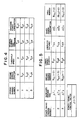
- Fig. 4 shows the contents of the table 1013 provided in correspondence to the ground markers shown in Fig. 1.
- the column for ground marker 0 contains the initial value of standard residual running time T co which is the minimum running time required at starting, and the initial value of standard power consumption E co which is the power consumption per unit weight at starting.
- Other column for ground marker i (i ⁇ ⁇ 3) contains the distance l ci from the departing station, the threshold speed v ci for the standard run, the standard (minimum) running time T ci for the remaining distance, and energy E ci used for the remaining distance.
- This table indicates that the running time will increase by ⁇ T j and power will be saved by the amount of ⁇ E j if the train runs following the lower target energy E pj for a distance of l Ej after the train has passed the ground marker N Ej , and also indicates that if this control is carried out, the control table of N Tj is included in the control and cannot be used.
- Figs. 6 to 8 are flowcharts of the microcomputer embodying the present invention.
- the flowchart of Fig. 6 represents the operation of the processing program which is executed when the train starts.
- the program initiated in response to the start command to the train, reads the running time between stations set on the target running time setting device 108 so as to set up the target running time (step 1601), sets the scheduled running time to the field of initial standard running time (T co ) in the condition table 1013 (step 1602), sets the power consumption to the field of initial standard power consumption (E co ) (step 1603), and set the power-saving control flag to "0" (step 1604).
- the flowchart of Figs. 7A and 7B shows the processing of the train control program which is executed at a sampling interval of ⁇ t (e.g., 100 ms).
- the program when initiated, first subtracts the sampling time ⁇ t from the target running time and scheduled running e (step 701). Subsequently, the program checks whether the power-saving control flag indicating the selection of the alternative table 1014 has a value j other than "0" (step 702), and resets the control flag (step 704) if the power-saving control flag is "1" (step 702) and if the running distance l is larger than the control completion distance l Ej (step 703).
- step 705 If the power-saving control flag is "0" (step 705) or the running distance l is in the vicinity of control completion distance l Ej of column j of power-saving control table under control e.g., 5 m to the end, (step 706), the program selects the power-saving control table (step 707).
- the lower target speed v TL is set larger (e.g., 200 km/h) (step 709), or if the control flag has a value j (step 708), the lower target speed v TL is obtained from the lower target energy E pj per unit weight (having the unit of m2/s2) and the potential energy E h at the current position l obtained from the running distance l with reference to the distance vs. potential energy table 1011 (step 710).
- E h and lower target speed v TL are calculated from the following equations.
- E h G ⁇ h (1)
- v TL 3.6.
- E pj - E h (2) where G is the gravitational acceleration (9.81 m/s2), h is the altitude (m) of the current position l, and constant 3.6 is a factor for converting the unit from m/s to km/h.
- the program calculates the upper target speed v TV from a speed corresponding to the contents of the limit speed signal register 102 (step 711).
- the lower target speed v TL obtained previously is made lower than the upper target speed v TV (step 712).
- the program calculates the brake command BN from the upper target speed v TV and the train speed v provided by the speed calculator 4, using, for example, the following equation (step 713).
- BN (v - v TV ) ⁇ B g (3)
- B g is the gain of the brake command applied to the deviation of speed.
- the traction command PN is made "0" (step 715), or if the former is absent, the traction command is calculated using, for example, the following equation (step 716).
- PN (v TL - v) ⁇ P g (4) where P g is the gain of traction command applied to the deviation of speed.
- the calculated brake command BN or traction command PN is fed to the drive/brake unit (step 717), and one cycle of processing is completed.
- Fig. 8 shows the flowchart of the process for selecting the alternative table of power-saving control, and this is an expansion of the step 707 shown in Fig. 7A.
- the program When the program enters this routine, it first checks the ground marker detector 107 to see whether the train has passed a ground marker during a period between the previous and present execution of the routine. If it is found that the train has passed a ground marker i, the program checks whether or not the train speed v is faster than the threshold speed v ci which is the speed to achieve the minimum running time plus a marginal speed (e.g., 2 km/h) (step 801), and if this is true, the program proceeds to step 802. In case the train has passed the ground marker i at a speed faster than the threshold speed v ci , the standard residual running time T ci and standard power consumption E ci are set to the scheduled running time and power consumption (step 802).
- steps 805, 810 and 811 are carried out by incrementing the value of j by the amount of power- saving control factor J. Namely, checking is made first whether the ground marker N Ej for the beginning of control in the jth record of table is equal to or larger than the current ground marker i, and also whether it is invalidated by the selection of other control record (step 805).
- the target running time is compared with the scheduled running time added by the increased running time ⁇ T j , and if the train can run in time shorter than the target running time even under this control (step 806), this column j control table is selected and the scheduled running time is increased by the increased running time ⁇ T j and scheduled power consumption is decreased by ⁇ E j (step 807).
- the control table N Tj which has no effect during this control is invalidated (step 808). If the ground marker number for the beginning of control in the table is equal to the ground marker number i which is currently passed by the train, the power-saving control flag is made to have value j (step 809). If the power-saving control factor J is smaller than j, the program returns to step 805, while incrementing j by one, and checks whether the table can be selected (steps 810 and 811).
- the train is operated while calculating the presumed arrival time at the next station and power consumption time to time, allowing the marginal time to be used for the power-saving operation, and moreover, the train operation under the specified power consumption is also made possible.
- the lower target power consumption E pj is set each position of ground marker, the calculation related to potential energy may be omitted if the railroad has small variation of slope.
- the alternative table for power-saving 1014 of J in number has the priority in the ascending order of the number, allowing the marginal time to be spent later and the like.
- the control table may be selected not only based on the running time, but on the target power consumption, or alternatively, it may be selected solely based on the target power consumption.
- the location of the train is determined using ground markers, it may be determined solely based on the running distance l from the departing station.
- the output of the distance calculator may be corrected using the running distance l obtained from the count at the detection of the ground marker and the actual distance l ci in the table.
- this embodiment has the information table on the increased running time and saved power consumption when train is operated to follow the lower target speed or lower target power consumption after the train has passed one or more positions between two stations, allowing the selection of optimal control at each position based on the target running time, target power consumption, and the like, whereby the train can be operated to meet conditions of arrival time at the next station and power consumption.
Landscapes
- Engineering & Computer Science (AREA)
- Mechanical Engineering (AREA)
- Electric Propulsion And Braking For Vehicles (AREA)
- Train Traffic Observation, Control, And Security (AREA)
Applications Claiming Priority (4)
| Application Number | Priority Date | Filing Date | Title |
|---|---|---|---|
| JP5641/83 | 1983-01-17 | ||
| JP58005641A JPS59132705A (ja) | 1983-01-17 | 1983-01-17 | 列車自動運転方法 |
| JP103487/83 | 1983-06-09 | ||
| JP58103487A JPH0646842B2 (ja) | 1983-06-09 | 1983-06-09 | 列車自動運転方法 |
Related Parent Applications (1)
| Application Number | Title | Priority Date | Filing Date |
|---|---|---|---|
| EP84100403.9 Division | 1984-01-16 |
Publications (3)
| Publication Number | Publication Date |
|---|---|
| EP0257662A2 true EP0257662A2 (fr) | 1988-03-02 |
| EP0257662A3 EP0257662A3 (en) | 1988-05-18 |
| EP0257662B1 EP0257662B1 (fr) | 1992-04-08 |
Family
ID=26339609
Family Applications (2)
| Application Number | Title | Priority Date | Filing Date |
|---|---|---|---|
| EP84100403A Expired EP0114633B1 (fr) | 1983-01-17 | 1984-01-16 | Dispositif de commande automatique d'un véhicule |
| EP87114703A Expired - Lifetime EP0257662B1 (fr) | 1983-01-17 | 1984-01-16 | Méthode pour commander automatiquement un véhicule |
Family Applications Before (1)
| Application Number | Title | Priority Date | Filing Date |
|---|---|---|---|
| EP84100403A Expired EP0114633B1 (fr) | 1983-01-17 | 1984-01-16 | Dispositif de commande automatique d'un véhicule |
Country Status (3)
| Country | Link |
|---|---|
| US (1) | US4617627A (fr) |
| EP (2) | EP0114633B1 (fr) |
| DE (2) | DE3477554D1 (fr) |
Cited By (22)
| Publication number | Priority date | Publication date | Assignee | Title |
|---|---|---|---|---|
| WO1982002338A1 (fr) * | 1981-01-09 | 1982-07-22 | Martin A Lerner | Complexe de faible poids moleculaire de l'acide polyriboinosinique-polyribocytitdylique et procede d'induction d'interferon |
| AU616093B2 (en) * | 1988-12-23 | 1991-10-17 | Hitachi Limited | Control equipment and control method of electric rolling stock |
| EP0389610A4 (en) * | 1988-09-28 | 1992-09-16 | Teknis Systems (Australia) Pty. Ltd. | A system for energy conservation on rail vehicles |
| EP0467377A3 (en) * | 1990-07-18 | 1993-07-21 | Hitachi, Ltd. | Method of producing a train running plan |
| EP0693411A1 (fr) * | 1994-07-21 | 1996-01-24 | Gec Alsthom Transport Sa | Système de pilotage automatique et procédé d'élaboration d'une consigne de vitesse dans un tel système |
| FR2739599A1 (fr) * | 1995-10-06 | 1997-04-11 | Renault | Procede de gestion de la consigne optimisee en vitesse du groupe motopropulseur d'un vehicule electrique automobile |
| WO1999014093A1 (fr) * | 1997-09-12 | 1999-03-25 | New York Air Brake Corporation | Procede d'optimisation du fonctionnement d'un train et de la formation a la conduite d'un train |
| US6263266B1 (en) | 1998-09-11 | 2001-07-17 | New York Air Brake Corporation | Method of optimizing train operation and training |
| US6332106B1 (en) | 1999-09-16 | 2001-12-18 | New York Air Brake Corporation | Train handling techniques and analysis |
| US6748303B2 (en) | 2002-09-20 | 2004-06-08 | New York Air Brake Corporation | Variable exception reporting |
| US7073753B2 (en) | 1996-09-13 | 2006-07-11 | New York Airbrake Corporation | Integrated train control |
| US7096171B2 (en) | 2002-08-07 | 2006-08-22 | New York Air Brake Corporation | Train simulator and playback station |
| US7143017B2 (en) | 2002-06-25 | 2006-11-28 | New York Air Brake Corporation | Remote control locomotive simulator |
| US7188341B1 (en) | 1999-09-24 | 2007-03-06 | New York Air Brake Corporation | Method of transferring files and analysis of train operational data |
| US7647141B2 (en) | 2002-08-07 | 2010-01-12 | New York Air Brake Corporation | Advanced simulation capture and reporting tools |
| US8538608B2 (en) | 2009-09-09 | 2013-09-17 | General Electric Company | Control system and method for remotely isolating powered units in a rail vehicle system |
| US8565946B2 (en) | 2011-07-01 | 2013-10-22 | General Electric Company | System and method for vehicle control |
| US9079589B2 (en) | 2009-09-09 | 2015-07-14 | General Electric Company | Control system and method for remotely isolating powered units in a vehicle system |
| US9156477B2 (en) | 2006-03-20 | 2015-10-13 | General Electric Company | Control system and method for remotely isolating powered units in a vehicle system |
| US9201409B2 (en) | 2006-03-20 | 2015-12-01 | General Electric Company | Fuel management system and method |
| US9733625B2 (en) | 2006-03-20 | 2017-08-15 | General Electric Company | Trip optimization system and method for a train |
| EP3090919A4 (fr) * | 2013-12-17 | 2017-11-29 | Kabushiki Kaisha Toshiba | Dispositif de création de plan de service |
Families Citing this family (35)
| Publication number | Priority date | Publication date | Assignee | Title |
|---|---|---|---|---|
| US4956779A (en) * | 1988-11-22 | 1990-09-11 | General Signal Corporation | Digital overspeed controller for use in a vital processing system |
| EP0539885B1 (fr) * | 1991-10-25 | 1997-04-23 | Kabushiki Kaisha Toshiba | Appareil de calcul d'un plan de roulage optimal d'un train et système qui s'y rapporte |
| US5364047A (en) * | 1993-04-02 | 1994-11-15 | General Railway Signal Corporation | Automatic vehicle control and location system |
| NL1000896C2 (nl) * | 1995-07-28 | 1997-01-31 | Ns Railbedrijven Bv | Werkwijze en systeem voor het optimaliseren van het rijgedrag van een voertuig, bij voorkeur een railvoertuig. |
| US6081878A (en) | 1997-03-31 | 2000-06-27 | Lexar Media, Inc. | Increasing the memory performance of flash memory devices by writing sectors simultaneously to multiple flash memory devices |
| US5887268A (en) * | 1995-10-31 | 1999-03-23 | Honda Giken Kogyo Kabushiki Kaisha | Automatically driven motor vehicle |
| CA2281683C (fr) * | 1997-02-07 | 2005-11-22 | Ge-Harris Railway Electronics, L.L.C. | Dispositif et procede servant a assurer le fonctionnement automatique d'un train |
| JP3723766B2 (ja) * | 2001-12-04 | 2005-12-07 | 株式会社日立製作所 | 列車制御方法および装置 |
| US9233696B2 (en) | 2006-03-20 | 2016-01-12 | General Electric Company | Trip optimizer method, system and computer software code for operating a railroad train to minimize wheel and track wear |
| US10569792B2 (en) | 2006-03-20 | 2020-02-25 | General Electric Company | Vehicle control system and method |
| US10308265B2 (en) | 2006-03-20 | 2019-06-04 | Ge Global Sourcing Llc | Vehicle control system and method |
| US8924049B2 (en) | 2003-01-06 | 2014-12-30 | General Electric Company | System and method for controlling movement of vehicles |
| RU2292273C1 (ru) * | 2005-06-06 | 2007-01-27 | Александр Николаевич Гаридов | Устройство для автоматической оценки и регулирования потребной мощности тяговых электродвигателей городского электротранспорта |
| US20070083782A1 (en) * | 2005-10-11 | 2007-04-12 | Silicon Integrated Systems Corp. | Power configuration scheme of computer |
| US8473127B2 (en) | 2006-03-20 | 2013-06-25 | General Electric Company | System, method and computer software code for optimizing train operations considering rail car parameters |
| US8126601B2 (en) | 2006-03-20 | 2012-02-28 | General Electric Company | System and method for predicting a vehicle route using a route network database |
| US8249763B2 (en) | 2006-03-20 | 2012-08-21 | General Electric Company | Method and computer software code for uncoupling power control of a distributed powered system from coupled power settings |
| US9266542B2 (en) | 2006-03-20 | 2016-02-23 | General Electric Company | System and method for optimized fuel efficiency and emission output of a diesel powered system |
| US8290645B2 (en) | 2006-03-20 | 2012-10-16 | General Electric Company | Method and computer software code for determining a mission plan for a powered system when a desired mission parameter appears unobtainable |
| US8788135B2 (en) | 2006-03-20 | 2014-07-22 | General Electric Company | System, method, and computer software code for providing real time optimization of a mission plan for a powered system |
| US8370007B2 (en) | 2006-03-20 | 2013-02-05 | General Electric Company | Method and computer software code for determining when to permit a speed control system to control a powered system |
| US9527518B2 (en) | 2006-03-20 | 2016-12-27 | General Electric Company | System, method and computer software code for controlling a powered system and operational information used in a mission by the powered system |
| US8370006B2 (en) * | 2006-03-20 | 2013-02-05 | General Electric Company | Method and apparatus for optimizing a train trip using signal information |
| US8768543B2 (en) | 2006-03-20 | 2014-07-01 | General Electric Company | Method, system and computer software code for trip optimization with train/track database augmentation |
| US8401720B2 (en) | 2006-03-20 | 2013-03-19 | General Electric Company | System, method, and computer software code for detecting a physical defect along a mission route |
| US7447571B2 (en) | 2006-04-24 | 2008-11-04 | New York Air Brake Corporation | Method of forecasting train speed |
| US9834237B2 (en) | 2012-11-21 | 2017-12-05 | General Electric Company | Route examining system and method |
| US8234023B2 (en) | 2009-06-12 | 2012-07-31 | General Electric Company | System and method for regulating speed, power or position of a powered vehicle |
| US9669851B2 (en) | 2012-11-21 | 2017-06-06 | General Electric Company | Route examination system and method |
| US9026348B2 (en) | 2012-12-21 | 2015-05-05 | Honda Motor Co., Ltd. | System and method for brake coaching |
| US10457307B2 (en) | 2016-06-08 | 2019-10-29 | Westinghouse Air Brake Technologies Corporation | Wireless crossing activation system and method |
| US10654500B2 (en) * | 2015-06-12 | 2020-05-19 | Westinghouse Air Brake Technologies Corporation | Arrival time and location targeting system and method |
| US10279823B2 (en) * | 2016-08-08 | 2019-05-07 | General Electric Company | System for controlling or monitoring a vehicle system along a route |
| CN113353077B (zh) * | 2021-06-11 | 2024-07-05 | 中汽创智科技有限公司 | 车辆行驶控制方法、装置及设备 |
| EP4122793A1 (fr) * | 2021-07-22 | 2023-01-25 | Siemens Mobility GmbH | Procédé et dispositif de sécurisation de train destiné à la détermination assistée par ordinateur de la vitesse maximale de fonctionnement d'un véhicule guidé |
Family Cites Families (6)
| Publication number | Priority date | Publication date | Assignee | Title |
|---|---|---|---|---|
| CH464283A (fr) * | 1967-10-23 | 1968-10-31 | Secheron Atel | Dispositif électronique de commande automatique d'un convoi ferroviaire |
| FR2351815A1 (fr) * | 1976-05-19 | 1977-12-16 | Citroen Sa | Dispositif de commande de limitation de vitesse pour vehicule, notamment automobile |
| US4179739A (en) * | 1978-02-13 | 1979-12-18 | Virnot Alain D | Memory controlled process for railraod traffic management |
| US4181943A (en) * | 1978-05-22 | 1980-01-01 | Hugg Steven B | Speed control device for trains |
| ZA792482B (en) * | 1978-06-10 | 1980-06-25 | Signal Co Ltd | Railway control signal dynamic output interlocking systems |
| DE3026652A1 (de) * | 1980-07-14 | 1982-02-11 | Siemens AG, 1000 Berlin und 8000 München | Einrichtung zum energieoptimalen fahren von schienenfahrzeugen in nahverkehrssystemen |
-
1984
- 1984-01-13 US US06/570,500 patent/US4617627A/en not_active Expired - Lifetime
- 1984-01-16 DE DE8484100403T patent/DE3477554D1/de not_active Expired
- 1984-01-16 EP EP84100403A patent/EP0114633B1/fr not_active Expired
- 1984-01-16 EP EP87114703A patent/EP0257662B1/fr not_active Expired - Lifetime
- 1984-01-16 DE DE8787114703T patent/DE3485644D1/de not_active Expired - Lifetime
Cited By (28)
| Publication number | Priority date | Publication date | Assignee | Title |
|---|---|---|---|---|
| WO1982002338A1 (fr) * | 1981-01-09 | 1982-07-22 | Martin A Lerner | Complexe de faible poids moleculaire de l'acide polyriboinosinique-polyribocytitdylique et procede d'induction d'interferon |
| EP0389610A4 (en) * | 1988-09-28 | 1992-09-16 | Teknis Systems (Australia) Pty. Ltd. | A system for energy conservation on rail vehicles |
| AU616093B2 (en) * | 1988-12-23 | 1991-10-17 | Hitachi Limited | Control equipment and control method of electric rolling stock |
| EP0467377A3 (en) * | 1990-07-18 | 1993-07-21 | Hitachi, Ltd. | Method of producing a train running plan |
| US6067496A (en) * | 1994-07-21 | 2000-05-23 | Gec Alsthom Transport Sa | Automatic driver system, and a method of generating a speed reference in such a system |
| EP0693411A1 (fr) * | 1994-07-21 | 1996-01-24 | Gec Alsthom Transport Sa | Système de pilotage automatique et procédé d'élaboration d'une consigne de vitesse dans un tel système |
| FR2722894A1 (fr) * | 1994-07-21 | 1996-01-26 | Gec Alsthom Transport Sa | Systeme de pilotage automatique et procede d'elaboration d'une consigne de vitesse dans un tel systeme |
| FR2739599A1 (fr) * | 1995-10-06 | 1997-04-11 | Renault | Procede de gestion de la consigne optimisee en vitesse du groupe motopropulseur d'un vehicule electrique automobile |
| US7073753B2 (en) | 1996-09-13 | 2006-07-11 | New York Airbrake Corporation | Integrated train control |
| US6144901A (en) * | 1997-09-12 | 2000-11-07 | New York Air Brake Corporation | Method of optimizing train operation and training |
| US6587764B2 (en) | 1997-09-12 | 2003-07-01 | New York Air Brake Corporation | Method of optimizing train operation and training |
| WO1999014093A1 (fr) * | 1997-09-12 | 1999-03-25 | New York Air Brake Corporation | Procede d'optimisation du fonctionnement d'un train et de la formation a la conduite d'un train |
| US6263266B1 (en) | 1998-09-11 | 2001-07-17 | New York Air Brake Corporation | Method of optimizing train operation and training |
| US6622068B2 (en) | 1998-09-11 | 2003-09-16 | New York Air Brake Corporation | Method of optimizing train operation and training |
| US6332106B1 (en) | 1999-09-16 | 2001-12-18 | New York Air Brake Corporation | Train handling techniques and analysis |
| US7188341B1 (en) | 1999-09-24 | 2007-03-06 | New York Air Brake Corporation | Method of transferring files and analysis of train operational data |
| US7263475B2 (en) | 1999-09-24 | 2007-08-28 | New York Air Brake Corporation | Method of transferring files and analysis of train operational data |
| US7143017B2 (en) | 2002-06-25 | 2006-11-28 | New York Air Brake Corporation | Remote control locomotive simulator |
| US7647141B2 (en) | 2002-08-07 | 2010-01-12 | New York Air Brake Corporation | Advanced simulation capture and reporting tools |
| US7096171B2 (en) | 2002-08-07 | 2006-08-22 | New York Air Brake Corporation | Train simulator and playback station |
| US6748303B2 (en) | 2002-09-20 | 2004-06-08 | New York Air Brake Corporation | Variable exception reporting |
| US9156477B2 (en) | 2006-03-20 | 2015-10-13 | General Electric Company | Control system and method for remotely isolating powered units in a vehicle system |
| US9201409B2 (en) | 2006-03-20 | 2015-12-01 | General Electric Company | Fuel management system and method |
| US9733625B2 (en) | 2006-03-20 | 2017-08-15 | General Electric Company | Trip optimization system and method for a train |
| US8538608B2 (en) | 2009-09-09 | 2013-09-17 | General Electric Company | Control system and method for remotely isolating powered units in a rail vehicle system |
| US9079589B2 (en) | 2009-09-09 | 2015-07-14 | General Electric Company | Control system and method for remotely isolating powered units in a vehicle system |
| US8565946B2 (en) | 2011-07-01 | 2013-10-22 | General Electric Company | System and method for vehicle control |
| EP3090919A4 (fr) * | 2013-12-17 | 2017-11-29 | Kabushiki Kaisha Toshiba | Dispositif de création de plan de service |
Also Published As
| Publication number | Publication date |
|---|---|
| EP0114633B1 (fr) | 1989-04-05 |
| EP0114633A1 (fr) | 1984-08-01 |
| US4617627A (en) | 1986-10-14 |
| DE3485644D1 (de) | 1992-05-14 |
| EP0257662A3 (en) | 1988-05-18 |
| DE3477554D1 (en) | 1989-05-11 |
| EP0257662B1 (fr) | 1992-04-08 |
Similar Documents
| Publication | Publication Date | Title |
|---|---|---|
| EP0257662B1 (fr) | Méthode pour commander automatiquement un véhicule | |
| EP0092832A2 (fr) | Méthode et dispositif pour arrêter un véhicule à une position déterminée | |
| EP4027113A1 (fr) | Procédé et appareil de planification de déplacement | |
| EP3088240A1 (fr) | Dispositif de création de courbe de conduite, dispositif d'assistance à la conduite, dispositif de commande de conduite et procédé de création de courbe de conduite | |
| CN109070765A (zh) | 列车控制装置、方法以及程序 | |
| CN112249096A (zh) | 一种城市轨道交通车站的精确停车方法 | |
| JP6118124B2 (ja) | 目標速度決定装置、目標速度決定方法及びプログラム、並びに、車両制御装置及び車両 | |
| EP3238980B1 (fr) | Dispositif de fonctionnement automatique de train, procédé de commande train train automatique, et programme | |
| JPH06284519A (ja) | 列車走行制御装置 | |
| JPH022786B2 (fr) | ||
| JPH0799708A (ja) | 列車自動運転装置 | |
| CN116767308B (zh) | 半独立路权和混合路权下的有轨电车速度诱导方法 | |
| KR930002843B1 (ko) | 엘리베이터 카아용 속도 패턴 발생방법 및 장치 | |
| JP2000156920A (ja) | 移動体自動制御装置 | |
| CN117087705A (zh) | 一种基于矿区的低速巡航速度规划方法及系统 | |
| JPH076875B2 (ja) | 自動運転制御装置 | |
| JPH0479705A (ja) | 列車運転方式の作成方式 | |
| JPH03117305A (ja) | 車両定位置停止制御方法 | |
| JPH0834267A (ja) | 電鉄負荷予測装置 | |
| JPS6151482B2 (fr) | ||
| JPH03117306A (ja) | 車両自動制御方法 | |
| JPH05112243A (ja) | 列車自動運転システム | |
| JPH089515A (ja) | 車両の定時運転制御装置 | |
| JPH06103961B2 (ja) | 定位置停車制御方法 | |
| JPH04289706A (ja) | 列車の自動運転方法 |
Legal Events
| Date | Code | Title | Description |
|---|---|---|---|
| PUAI | Public reference made under article 153(3) epc to a published international application that has entered the european phase |
Free format text: ORIGINAL CODE: 0009012 |
|
| 17P | Request for examination filed |
Effective date: 19871008 |
|
| AC | Divisional application: reference to earlier application |
Ref document number: 114633 Country of ref document: EP |
|
| AK | Designated contracting states |
Kind code of ref document: A2 Designated state(s): DE FR GB |
|
| PUAL | Search report despatched |
Free format text: ORIGINAL CODE: 0009013 |
|
| AK | Designated contracting states |
Kind code of ref document: A3 Designated state(s): DE FR GB |
|
| RIN1 | Information on inventor provided before grant (corrected) |
Inventor name: IHARA,HIROKAZU Inventor name: MIYAMOTO,SHOJI Inventor name: YASUNOBU, SEIJI |
|
| 17Q | First examination report despatched |
Effective date: 19900821 |
|
| GRAA | (expected) grant |
Free format text: ORIGINAL CODE: 0009210 |
|
| AC | Divisional application: reference to earlier application |
Ref document number: 114633 Country of ref document: EP |
|
| AK | Designated contracting states |
Kind code of ref document: B1 Designated state(s): DE FR GB |
|
| REF | Corresponds to: |
Ref document number: 3485644 Country of ref document: DE Date of ref document: 19920514 |
|
| ET | Fr: translation filed | ||
| PG25 | Lapsed in a contracting state [announced via postgrant information from national office to epo] |
Ref country code: GB Effective date: 19930116 |
|
| PLBE | No opposition filed within time limit |
Free format text: ORIGINAL CODE: 0009261 |
|
| STAA | Information on the status of an ep patent application or granted ep patent |
Free format text: STATUS: NO OPPOSITION FILED WITHIN TIME LIMIT |
|
| 26N | No opposition filed | ||
| GBPC | Gb: european patent ceased through non-payment of renewal fee |
Effective date: 19930116 |
|
| PGFP | Annual fee paid to national office [announced via postgrant information from national office to epo] |
Ref country code: FR Payment date: 19981117 Year of fee payment: 16 |
|
| PG25 | Lapsed in a contracting state [announced via postgrant information from national office to epo] |
Ref country code: FR Free format text: LAPSE BECAUSE OF NON-PAYMENT OF DUE FEES Effective date: 20000929 |
|
| REG | Reference to a national code |
Ref country code: FR Ref legal event code: ST |
|
| PGFP | Annual fee paid to national office [announced via postgrant information from national office to epo] |
Ref country code: DE Payment date: 20030310 Year of fee payment: 20 |