EP0259032A1 - Pneumatischer Förderer - Google Patents
Pneumatischer Förderer Download PDFInfo
- Publication number
- EP0259032A1 EP0259032A1 EP87307119A EP87307119A EP0259032A1 EP 0259032 A1 EP0259032 A1 EP 0259032A1 EP 87307119 A EP87307119 A EP 87307119A EP 87307119 A EP87307119 A EP 87307119A EP 0259032 A1 EP0259032 A1 EP 0259032A1
- Authority
- EP
- European Patent Office
- Prior art keywords
- air
- conveyor
- articles
- sidewalls
- sidewall
- Prior art date
- Legal status (The legal status is an assumption and is not a legal conclusion. Google has not performed a legal analysis and makes no representation as to the accuracy of the status listed.)
- Withdrawn
Links
- 239000003570 air Substances 0.000 claims description 113
- 238000000034 method Methods 0.000 claims description 17
- 238000011144 upstream manufacturing Methods 0.000 claims description 12
- 239000012080 ambient air Substances 0.000 claims description 8
- 230000000694 effects Effects 0.000 claims description 8
- 238000005188 flotation Methods 0.000 claims description 6
- LENZDBCJOHFCAS-UHFFFAOYSA-N tris Chemical compound OCC(N)(CO)CO LENZDBCJOHFCAS-UHFFFAOYSA-N 0.000 claims 1
- 235000013361 beverage Nutrition 0.000 description 3
- 230000000630 rising effect Effects 0.000 description 3
- 239000012530 fluid Substances 0.000 description 2
- 229920003023 plastic Polymers 0.000 description 2
- 239000004033 plastic Substances 0.000 description 2
- 238000000926 separation method Methods 0.000 description 2
- 230000001133 acceleration Effects 0.000 description 1
- 239000004411 aluminium Substances 0.000 description 1
- 229910052782 aluminium Inorganic materials 0.000 description 1
- XAGFODPZIPBFFR-UHFFFAOYSA-N aluminium Chemical compound [Al] XAGFODPZIPBFFR-UHFFFAOYSA-N 0.000 description 1
- 230000004888 barrier function Effects 0.000 description 1
- 238000005553 drilling Methods 0.000 description 1
- 235000015203 fruit juice Nutrition 0.000 description 1
- 229910052751 metal Inorganic materials 0.000 description 1
- 239000002184 metal Substances 0.000 description 1
- 230000003068 static effect Effects 0.000 description 1
Images


Classifications
-
- B—PERFORMING OPERATIONS; TRANSPORTING
- B65—CONVEYING; PACKING; STORING; HANDLING THIN OR FILAMENTARY MATERIAL
- B65G—TRANSPORT OR STORAGE DEVICES, e.g. CONVEYORS FOR LOADING OR TIPPING, SHOP CONVEYOR SYSTEMS OR PNEUMATIC TUBE CONVEYORS
- B65G51/00—Conveying articles through pipes or tubes by fluid flow or pressure; Conveying articles over a flat surface, e.g. the base of a trough, by jets located in the surface
- B65G51/02—Directly conveying the articles, e.g. slips, sheets, stockings, containers or workpieces, by flowing gases
- B65G51/03—Directly conveying the articles, e.g. slips, sheets, stockings, containers or workpieces, by flowing gases over a flat surface or in troughs
-
- B—PERFORMING OPERATIONS; TRANSPORTING
- B65—CONVEYING; PACKING; STORING; HANDLING THIN OR FILAMENTARY MATERIAL
- B65G—TRANSPORT OR STORAGE DEVICES, e.g. CONVEYORS FOR LOADING OR TIPPING, SHOP CONVEYOR SYSTEMS OR PNEUMATIC TUBE CONVEYORS
- B65G2201/00—Indexing codes relating to handling devices, e.g. conveyors, characterised by the type of product or load being conveyed or handled
- B65G2201/02—Articles
- B65G2201/0202—Agricultural and processed food products
- B65G2201/0211—Fruits and vegetables
-
- B—PERFORMING OPERATIONS; TRANSPORTING
- B65—CONVEYING; PACKING; STORING; HANDLING THIN OR FILAMENTARY MATERIAL
- B65G—TRANSPORT OR STORAGE DEVICES, e.g. CONVEYORS FOR LOADING OR TIPPING, SHOP CONVEYOR SYSTEMS OR PNEUMATIC TUBE CONVEYORS
- B65G2201/00—Indexing codes relating to handling devices, e.g. conveyors, characterised by the type of product or load being conveyed or handled
- B65G2201/02—Articles
- B65G2201/0235—Containers
- B65G2201/0244—Bottles
Definitions
- This invention relates to air conveying apparatus for use with generally cylindrical articles and more particularly to a controlled speed coverless air conveyor wherein the articles are enveloped in a moving mass or stream of air which acts uniformly along the sidewalls of the articles so that undesired tipping is minimized.
- the invention also relates to methods of conveying articles.
- a mass air conveying apparatus is disclosed in US-A 4 456 406.
- air is supplied by a plenum through a jet board forming the top surface of a conveyor forming part of the apparatus.
- the sidewalls of the conveyor can be either open or closed, and a cover is provided having widely spaced apertures to form high pressure areas therebetween to create air barriers for the containers to maintain them in a loose separated condition as they move through the conveyor.
- the top cover prevents the containers from tipping over.
- US-A-4 561 806 is directed to a vertical single filer conveyor system which also supplies air to the surface through a jet board by means of a plenum thereunder.
- the single filer has converging closed sidewalls and a top cover with widely spaced apertures for the same purpose as described in the immediately preceding paragraph. Acceleration jets are also provided for increasing the speed of the containers as they are brought into single file.
- Air conveyors and air single filers have substantial advantages over mechanical conveyors and single filers in that much higher speed of handling of the containers is possible.
- one of the disadvantages is that in order to create the high pressure within the conveyor or single filer it is necessary to have a top cover which is located just above the top of the containers so that they will not tip over and to create sufficiently high air pressure to cause proper separation of the articles. Because of this, each system is set up to handle containers of a particular height. When it is necessary to use the system with containers of a different height, the cover on the table must be either raised or lowered. This results in substantial downtime and, of course, increases labour costs. Furthermore, if containers jam or otherwise become improperly aligned within the prior systems, it is necessary to remove the top cover in order to reach them to remove them or correct their alignment.
- an air conveyor for conveying articles at constant speed, said conveyor being characterized by a surface extending from an upstream location to a downstream location for moving the article, first and second opposite side edges and an underside with a pattern of nearly vertical flotation air jets with a very slight downstream vector communicating the surface and the underside, a plenum connectable to a source of pressure gas and communicating with the underside of the conveyor, and a sidewall along each of said side edges having a height at least as high as the tallest article to be conveyed on said conveyor to form an air dam so that substantially uniform, higher than ambient air pressure is formed which moves as a stream above said conveyor.
- a method of moving articles along an air conveyor from an upstream location to a downstream location being characterized by the steps of providing a conveyor surface with a pattern of flotation jets which are substantially perpendicular to the surface but have a very slight downstream angle, directing air through the jets in a sufficient volume to create a mass of air of higher than ambient air pressure above the surface to separate the articles from each other and move them downsteam at a substantially constant velocity, and containing the mass of air along and upwardly of the side edges of the conveyor surface to a height at least as high as the articles being conveyed so that the pressure of the mass of air remains substantially constant above the conveyor surface and acts against the sidewalls of the articles to impart movement to the articles in a downstream location.
- a method of moving articles along a coverless air conveyor at uniform speed without jamming from an upstream location to a downstream location the method being characterized by the steps of forming a zone having a volume of air at higher than ambient air pressure above the surface of the conveyor for at least the height of the articles being conveyed, so that the air acts on all exterior surfaces of the articles and the pressure is sufficient to maintain the articles in a separated loose pack configuration supporting the articles above the conveyor surface on air, and moving the volume of air as a uniform mass within the zone from the upstream location to the downstream location so that the articles within the mass of air move along with the air mass.
- a method of moving articles which have vertical surface along a coverless air conveyor at uniform speed without jamming from an upstream location to a downstream location, said method comprising: creating a substantially uniform mass of rising air above the surface of the conveyor which is at higher than ambient air pressure and moves toward the downstream location as it rises; and using the rising air mass to lift and move the articles in a uniform manner toward the downstream location by exerting a uniform downstream force along the vertical surfaces of the articles.
- a method of moving cylindrical articles along a coverless air conveyor at uniform speed without jamming from an upstream location to a downstream location comprising: fluidizing the articles in a zone of higher than ambient air rising from the surface of the conveyor and enveloping all sides of the articles, the air flow being sufficient to support the articles above the conveyor surface; and causing the air mass to impinge substantially uniformly along the sides of the containers with a downstream vector sufficient to move the articles as a fluid toward the downstream location.
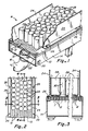
- a mass air conveyor is provided, as shown in Figure 1 having a conveyor surface 10 in the form of a jet board having a plurality of flotation openings or air jets 12 formed therein, as by drilling. Air is supplied to the air jets by means of a plenum 14 mounted below the conveyor surface 10. Air is supplied through the plenum, as through an inlet 16, and is controlled by a damper 18 connected to a control knob 20 on the outside of the plenum by a control rod 22. Sidewalls 24 are provided along opposite sides of the jet board 10 and attached thereto, as by screws 26 or other fastening means.
- the containers 28 will be supported and enveloped by a large air mass. As this mass moves, it contacts the sidewalls of the containers uniformly and moves them downstream in a very precisely controlled manner without tipping.
- the containers are suspended in the fluid medium, such as air, and move with it in much the same way as leaves float down a stream.
- the containers take on or assume a loose configuration with respect to each other, as best seen in Figure 2, as the air flows up around all sides of the containers as seen in Figures 3 and 4.
- the angle of air jets 12 in the downstream direction is on the order of between 15 minutes and 5°.
- the air moves up along the surface of the containers as shown by arrows 30.
- the air also moves up around the containers as shown by arrows 30 in Figure 3.
- the air moving up along the forward sidewall surface of the can will create a slight partial vacuum along that surface, whereas the air moving up along the back sidewall will exert a positive pressure force thereon.
- a large volume of air will move up through the jet board in a substantially vertical direction which will suspend and carry the containers with it in accordance with the downstream vector of the angle of the jet board.
- This structure is to be carefully distinguished from that of the prior art where the jet angles are of a different order, such as 20° to 60° whereby the air impinges on the bottom of the containers and it is the force on the bottom of the containers which causes the containers to move.
- the force is distributed substantially uniformly along the entire sidewall surfaces of the containers.
- the apparatus can be used to convey articles other than containers.
- stacks of metal container ends 32 as used on cardboard containers, of the type used for frozen fruit juice can be conveyed.
- the problem encountered in conveying these previously was that when a large angle was used on the jets, the stream of air was of such velocity that it would sometimes peel the top container lid off of the stack. This would be particularly true in short stacks.
- Figure 6 shows a very shallow jet board angle, such as 3°, for conveying lightweight articles, such as aluminium containers 28 used in the beverage industry.
- Figure 7 shows a very shallow jet board angle, such as 3°, for conveying lightweight articles, such as aluminium containers 28 used in the beverage industry.
- the angle of the jets 12 must be steeper, such as on the order of 5° and the velocity of the air must be higher in order to lift and support the heavier weight of the stack of container ends, as compared to the weight of beverage containers, and to provide sufficient air velocity, flow and movement to move the stacks in a downstream direction.
- a single file coverless conveyor S has a conveyor surface or jet board 40 of substantially narrower width than conveyor surface 10 of Figure 1.
- This jet board 40 has a plurality of openings or jets 42 formed therein to communicate a plenum 44 mounted below the jet board 40 with the top surface of the jet board.
- Sidewalls 46 are provided on each side of the upper surface of jet board 40 and serve as air dams to confine the air issuing from the jets 42.
- This apparatus has utility with containers of different diameters and heights.
- the spacing of the sidewalls 46 is such that the smallest diameter containers, such as containers 48, when brought into contiguous relationship remain in an isosceles triangular configuration so that jamming cannot occur.
- the pressure is less at the center of the jet board than at the side edges, and the velocity of air is higher. Therefore, the containers will tend to be pulled into single file aligned with the center line of the jet board 40.
- containers of larger diameter such as containers 48 ⁇ , shown in dotted lines, can be used in this device and can be of a diameter up to that which is slightly less than the spacing of the sidewalls 46.
- the height of the containers can vary, but it is desirable that the sidewalls be at least as high as the tallest article to be conveyed, so that the air is confined and moves much in the same manner as the movement of a stream or river thereby acting on all surfaces of the container so that the forces are applied to the sidewalls of the container for carrying them downstream rather than just being applied to the bottoms thereof.
- the containers 48 are shown as being of the type which has a smaller diameter bottom 50 than the diameter of the sidewalls thereof, such as plastics jars.
- Containers of this type are quite top heavy and can easily be tipped over if the forces applied thereto are not uniform.
- top covers With conventional air conveying equipment, it is necessary to use top covers to keep the containers upright, and in some instances to provide air jets through a plenum over the containers so that air is applied equally to the bottom surface of the container and the upper surface for keeping it upright.
- the present apparatus because of the large flows around the containers, thereby exerting forces all along the sidewalls of the containers, they are maintained in an upright condition and the presence of a cover is not required.
- the apparatus has been found satisfactory for mass conveying of jars, having the shape shown in Figures 8-11, using jet openings of 1.98 mm (5/64") at a 3° downstream angle and a static pressure of bars (1.2").
- the jars weigh 58 grams, have a base diameter of approximately 90 mm (3 1/2") and a height of 180 mm (7").
- the sidewalls are at least 180 mm (7") high.
- FIG. 12 An alternative embodiment of the invention is illustrated in Figure 12 wherein a conveyor jet board surface 10 ⁇ has inwardly tilted sidewalls, such as sidewall 24 ⁇ . Air is supplied to the jet board by plenum 14 through jets 12 which may be of the order of 1.98 mm (5/64") in diameter. An additional row of larger jet openings 56 are provided just inwardly of the bottom edge of sidewall 24 ⁇ . These may be of the order of 4.76 mm (3/16") in diameter. With this arrangement, a large volume of air can be provided at the lower portion of the sidewall which minimizes the tendency for the bottom of container 28 ⁇ to move against the bottom of the sidewall, and therefore remain upright.
- a coverless air conveyor has been provided for conveying containers of varying height and size at very precise speeds.
- a very shallow angle on the air jets i.e. between 15 minutes and 5°
- a stream or river of air is created above the conveyor surface which envelopes each of the containers and exerts a force on the sidewalls, as well as the bottom wall to carry them uniformly from an upstream location to a downstream location.
- the angle is very shallow, lightweight articles can be lifted and conveyed. With heavier articles, the angle must be slightly greater, and the pressure in the plenum must be increased.
- the absence of a top cover allows the operator to have access to the articles being conveyed in addition to the advantage of handling articles of varying height.
- the apparatus can be used with top heavy articles, i.e. such as jars having a small diameter base, and will maintain them in an upright condition, even in the absence of a top cover. As explained above, this is true because the air envelopes the articles and acts on the sidewalls in a uniform manner so that they are not tilted to any great extent of their vertical axis.
Landscapes
- Physics & Mathematics (AREA)
- Engineering & Computer Science (AREA)
- Fluid Mechanics (AREA)
- Mechanical Engineering (AREA)
- Spray Control Apparatus (AREA)
- Ventilation (AREA)
- Intermediate Stations On Conveyors (AREA)
- Attitude Control For Articles On Conveyors (AREA)
Applications Claiming Priority (2)
| Application Number | Priority Date | Filing Date | Title |
|---|---|---|---|
| US06/901,593 US4732513A (en) | 1986-08-29 | 1986-08-29 | Controlled speed coverless air conveyor |
| US901593 | 1986-08-29 |
Publications (1)
| Publication Number | Publication Date |
|---|---|
| EP0259032A1 true EP0259032A1 (de) | 1988-03-09 |
Family
ID=25414483
Family Applications (1)
| Application Number | Title | Priority Date | Filing Date |
|---|---|---|---|
| EP87307119A Withdrawn EP0259032A1 (de) | 1986-08-29 | 1987-08-12 | Pneumatischer Förderer |
Country Status (4)
| Country | Link |
|---|---|
| US (1) | US4732513A (de) |
| EP (1) | EP0259032A1 (de) |
| JP (1) | JPS6360812A (de) |
| AU (1) | AU7766487A (de) |
Cited By (3)
| Publication number | Priority date | Publication date | Assignee | Title |
|---|---|---|---|---|
| GB2240079A (en) * | 1990-01-19 | 1991-07-24 | Christopher Philip Morris | Material conveying or separation apparatus and air distribution plate therefor |
| WO2000006476A1 (en) * | 1998-07-30 | 2000-02-10 | Crown Simplimatic, Incorporated | Controlled speed air conveyor for unstable articles |
| WO2012177141A3 (en) * | 2011-05-12 | 2013-02-21 | Broerse Karel Peter August | Transport system for transporting non-ferrous metal objects |
Families Citing this family (21)
| Publication number | Priority date | Publication date | Assignee | Title |
|---|---|---|---|---|
| US4828434A (en) * | 1987-08-31 | 1989-05-09 | Goldco Industries, Inc. | Device, apparatus and method for distribution of fluid and selective movement of articles thereby |
| JPH0818678B2 (ja) * | 1989-09-05 | 1996-02-28 | 日本板硝子株式会社 | エアベッド搬送装置 |
| US5209387A (en) * | 1990-09-20 | 1993-05-11 | Eastman Kodak Company | Gas film conveyor for elongated strips of web material |
| US5280465A (en) * | 1992-07-15 | 1994-01-18 | Minnesota Mining And Manufacturing Company | Fluid drive system for a rotating medium |
| US5788425A (en) * | 1992-07-15 | 1998-08-04 | Imation Corp. | Flexible system for handling articles |
| US5484237A (en) * | 1992-12-29 | 1996-01-16 | Langenbeck; Keith A. | Pneumatic conveyor apparatus having air deflectors |
| US5549423A (en) * | 1993-06-24 | 1996-08-27 | Simplimatic Engineering Company | Damperless controlled speed air conveyor |
| US5478173A (en) * | 1993-06-24 | 1995-12-26 | Simplimatic Engineering Company | Damperless controlled speed air conveyor |
| USRE37532E1 (en) | 1993-06-24 | 2002-01-29 | Century Simplimatic, Inc. | Damperless controlled speed air conveyor |
| US5466096A (en) * | 1993-11-01 | 1995-11-14 | Simplimatic Engineering Company | Pressurized air conveyor |
| US5570977A (en) * | 1995-03-13 | 1996-11-05 | Goldco Industries, Inc. | Fluid conveyor for articles |
| US6286338B2 (en) | 1998-02-26 | 2001-09-11 | Visteon Global Technologies, Inc. | Block assembly for a gas-type lehr |
| JP2002529688A (ja) * | 1998-10-30 | 2002-09-10 | ハイ−スピード チェックウェイヤー コー インク | 空気圧式高速計量装置 |
| US20110197987A1 (en) * | 2008-05-01 | 2011-08-18 | Cabot Corporation | Manufacturing and Installation of Insulated Pipes or Elements Thereof |
| DK2851659T3 (da) * | 2013-09-23 | 2017-02-20 | Hd Wiegetechnik & Sondermaschinen Gmbh | Portionsvægt og drift af en portionsvægt. |
| CN103771134B (zh) * | 2014-01-22 | 2016-09-07 | 上海唯倍承机械设备有限公司 | 一种轻质瓶风力输送机 |
| CN106395321B (zh) * | 2016-08-28 | 2018-10-02 | 义乌市易开盖实业公司 | 未切边罐输送定位装置及其方法 |
| WO2021126876A1 (en) | 2019-12-16 | 2021-06-24 | AMP Robotics Corporation | A bidirectional air conveyor device for material sorting and other applications |
| US11465858B2 (en) | 2019-12-16 | 2022-10-11 | AMP Robotics Corporation | Actuated air conveyor device for material sorting and other applications |
| WO2021126879A1 (en) | 2019-12-16 | 2021-06-24 | AMP Robotics Corporation | A suction gripper cluster device for material sorting and other applications |
| US20250051105A1 (en) * | 2023-07-05 | 2025-02-13 | Dan R. Lowrey | Directional Air Conveyance System and Method |
Citations (3)
| Publication number | Priority date | Publication date | Assignee | Title |
|---|---|---|---|---|
| DE2523378A1 (de) * | 1975-05-27 | 1976-12-09 | Rudolph E Futer | Luftfilmfoerderer zum foerdern von auf ihm befindlichen gegenstaenden zu einer an seinem ende befindlichen ausgabestelle |
| US4456406A (en) * | 1980-04-07 | 1984-06-26 | Precision Metal Fabricators, Inc. | Air table system |
| US4561806A (en) * | 1983-01-31 | 1985-12-31 | Precision Metal Fabricators, Inc. | Vertical single filer conveyor system |
Family Cites Families (5)
| Publication number | Priority date | Publication date | Assignee | Title |
|---|---|---|---|---|
| US2805898A (en) * | 1955-01-18 | 1957-09-10 | Jr Edward A Willis | Fluid current conveyor for fragile articles |
| US3210124A (en) * | 1963-09-23 | 1965-10-05 | Gen Motors Corp | Air feed conveyor |
| US4395165A (en) * | 1980-12-19 | 1983-07-26 | International Business Machine Corp. | Chip shuttle track |
| US4444531A (en) * | 1981-12-01 | 1984-04-24 | Gca Corporation | Air track apparatus |
| ZA84706B (en) * | 1983-01-31 | 1985-07-31 | Precision Metal Fab | Verticle single filer conveyor system |
-
1986
- 1986-08-29 US US06/901,593 patent/US4732513A/en not_active Expired - Fee Related
-
1987
- 1987-08-12 EP EP87307119A patent/EP0259032A1/de not_active Withdrawn
- 1987-08-28 AU AU77664/87A patent/AU7766487A/en not_active Abandoned
- 1987-08-28 JP JP62214968A patent/JPS6360812A/ja active Pending
Patent Citations (3)
| Publication number | Priority date | Publication date | Assignee | Title |
|---|---|---|---|---|
| DE2523378A1 (de) * | 1975-05-27 | 1976-12-09 | Rudolph E Futer | Luftfilmfoerderer zum foerdern von auf ihm befindlichen gegenstaenden zu einer an seinem ende befindlichen ausgabestelle |
| US4456406A (en) * | 1980-04-07 | 1984-06-26 | Precision Metal Fabricators, Inc. | Air table system |
| US4561806A (en) * | 1983-01-31 | 1985-12-31 | Precision Metal Fabricators, Inc. | Vertical single filer conveyor system |
Cited By (5)
| Publication number | Priority date | Publication date | Assignee | Title |
|---|---|---|---|---|
| GB2240079A (en) * | 1990-01-19 | 1991-07-24 | Christopher Philip Morris | Material conveying or separation apparatus and air distribution plate therefor |
| GB2240079B (en) * | 1990-01-19 | 1994-04-06 | Christopher Philip Morris | Improvements relating to conveying and separation apparatus |
| US5388704A (en) * | 1990-01-19 | 1995-02-14 | Morris; Christopher P. | Relating to conveying and separation apparatus |
| WO2000006476A1 (en) * | 1998-07-30 | 2000-02-10 | Crown Simplimatic, Incorporated | Controlled speed air conveyor for unstable articles |
| WO2012177141A3 (en) * | 2011-05-12 | 2013-02-21 | Broerse Karel Peter August | Transport system for transporting non-ferrous metal objects |
Also Published As
| Publication number | Publication date |
|---|---|
| US4732513A (en) | 1988-03-22 |
| JPS6360812A (ja) | 1988-03-16 |
| AU7766487A (en) | 1988-03-03 |
Similar Documents
| Publication | Publication Date | Title |
|---|---|---|
| EP0259032A1 (de) | Pneumatischer Förderer | |
| CA1216536A (en) | Vertical single filer conveyor system | |
| EP0191584B1 (de) | Vakuumvorrichtung zur Reihenbildung von Behältern | |
| US5299889A (en) | Pneumatic conveyor apparatus | |
| EP0070931A1 (de) | Druckluftförderanlage für Flaschenteile | |
| US3953076A (en) | Bottle conveyor | |
| US4773522A (en) | Vacuum deadplate | |
| JPH048101Y2 (de) | ||
| EP0246000A2 (de) | Vorrichtung zum divergierenden Bilden einer Einzelreihe | |
| EP0132150B1 (de) | Vakuum-Überführungsförderer | |
| JP3305715B2 (ja) | 高速縦単列装置 | |
| EP0705212B1 (de) | Pneumatische fördereinrichtung mit dämpferlöser steuerung und verfahren zum fördern von gesammelten artikeln | |
| EP0002100B1 (de) | Verfahren und Vorrichtung zum Bewegen von Gegenständen durch Fliessbewegung auf einem Gaspolster | |
| CA2197002C (en) | Damperless controlled speed air conveyor | |
| US5451125A (en) | Controlled speed single file conveyor for multisize articles | |
| US6042307A (en) | Controlled speed air conveyor for unstable articles | |
| EP0249388A2 (de) | Vorrichtung zum Ineinanderstecken von Behältern | |
| EP0675768B1 (de) | Vorrichtung zur klassifizierung von artikeln | |
| US5478174A (en) | Controlled speed single file conveyor | |
| US5404991A (en) | Article orienting device | |
| US5339948A (en) | Conveyor apparatus with unloader | |
| JPS61111211A (ja) | 湾曲真空移送コンベヤ | |
| EP0207629A1 (de) | Vorrichtung zum Ausrichten von Gegenständen in einer Reihe mit einer Gegenblaseinrichtung | |
| USRE37532E1 (en) | Damperless controlled speed air conveyor | |
| JP3036845B2 (ja) | ダンパーレスな一定速度エアコンベア |
Legal Events
| Date | Code | Title | Description |
|---|---|---|---|
| PUAI | Public reference made under article 153(3) epc to a published international application that has entered the european phase |
Free format text: ORIGINAL CODE: 0009012 |
|
| AK | Designated contracting states |
Kind code of ref document: A1 Designated state(s): BE DE FR GB IT NL |
|
| RAP1 | Party data changed (applicant data changed or rights of an application transferred) |
Owner name: MEYER CONVEYAIR, INC. |
|
| 17P | Request for examination filed |
Effective date: 19880826 |
|
| 17Q | First examination report despatched |
Effective date: 19900702 |
|
| STAA | Information on the status of an ep patent application or granted ep patent |
Free format text: STATUS: THE APPLICATION IS DEEMED TO BE WITHDRAWN |
|
| 18D | Application deemed to be withdrawn |
Effective date: 19911223 |
|
| RIN1 | Information on inventor provided before grant (corrected) |
Inventor name: LENHART, RONALD A. |