EP0260206B1 - Maschine zur Herstellung eines neuartigen Fantasiegarns und Fantasiegarn, das auf dieser Maschine hergestellt wird - Google Patents
Maschine zur Herstellung eines neuartigen Fantasiegarns und Fantasiegarn, das auf dieser Maschine hergestellt wird Download PDFInfo
- Publication number
- EP0260206B1 EP0260206B1 EP19870420235 EP87420235A EP0260206B1 EP 0260206 B1 EP0260206 B1 EP 0260206B1 EP 19870420235 EP19870420235 EP 19870420235 EP 87420235 A EP87420235 A EP 87420235A EP 0260206 B1 EP0260206 B1 EP 0260206B1
- Authority
- EP
- European Patent Office
- Prior art keywords
- spindle
- core
- yarns
- effect
- yarn
- Prior art date
- Legal status (The legal status is an assumption and is not a legal conclusion. Google has not performed a legal analysis and makes no representation as to the accuracy of the status listed.)
- Expired - Lifetime
Links
- 230000000694 effects Effects 0.000 claims description 43
- 230000001360 synchronised effect Effects 0.000 claims description 4
- 238000007669 thermal treatment Methods 0.000 claims 1
- 238000004804 winding Methods 0.000 description 9
- 239000000470 constituent Substances 0.000 description 4
- 238000010586 diagram Methods 0.000 description 4
- 238000004519 manufacturing process Methods 0.000 description 3
- 241001080024 Telles Species 0.000 description 2
- 238000009434 installation Methods 0.000 description 2
- 238000000034 method Methods 0.000 description 2
- 238000006677 Appel reaction Methods 0.000 description 1
- 238000007792 addition Methods 0.000 description 1
- 238000010438 heat treatment Methods 0.000 description 1
- 238000012423 maintenance Methods 0.000 description 1
- 239000000463 material Substances 0.000 description 1
- 230000004048 modification Effects 0.000 description 1
- 238000012986 modification Methods 0.000 description 1
- 239000010453 quartz Substances 0.000 description 1
- VYPSYNLAJGMNEJ-UHFFFAOYSA-N silicon dioxide Inorganic materials O=[Si]=O VYPSYNLAJGMNEJ-UHFFFAOYSA-N 0.000 description 1
- 239000004753 textile Substances 0.000 description 1
Images

Classifications
-
- D—TEXTILES; PAPER
- D02—YARNS; MECHANICAL FINISHING OF YARNS OR ROPES; WARPING OR BEAMING
- D02G—CRIMPING OR CURLING FIBRES, FILAMENTS, THREADS, OR YARNS; YARNS OR THREADS
- D02G3/00—Yarns or threads, e.g. fancy yarns; Processes or apparatus for the production thereof, not otherwise provided for
- D02G3/22—Yarns or threads characterised by constructional features, e.g. blending, filament/fibre
- D02G3/34—Yarns or threads having slubs, knops, spirals, loops, tufts, or other irregular or decorative effects, i.e. effect yarns
Definitions
- the present invention relates to a machine for manufacturing fancy yarns. It also relates to the new type of fancy yarn obtained from such a machine.
- the invention relates more particularly to an improved machine making it possible to obtain, from at least two threads, both fancy threads having localized effects such as flamed, buttons, loops, as fancy threads having color and / or threads in which one of the constituents forms a core completely covered by the other constituent, the effects thus obtained are preferably linked by means of an additional thread known as a "binding thread".
- the invention also relates to the new type of wire obtained by the implementation of this machine.
- the core wire supplied with the parade enters the upper hollow spindle carrying the coil supporting the effect wire.
- the rotation of the coil surrounds the effect thread around the core, a needle or any other equivalent system possibly being used depending on the effect to be formed, then the intermediate thread thus formed passes inside the second. hollow spindle, the effect being linked by the binding wire coming from the coil carried by this second spindle.
- means making it possible to modify the speed of passage of the various constituents of the fancy yarn, such as modification of the speed of the intermediate yarn and / or of the winding speed are used.
- means for winding up the fancy yarn formed characterized in that the control shafts of the core and effect yarn deliverers and of the winding system are driven individually by synchronized motors which are controlled by a computer controlling a divider + converter converter in numerical control frequency so that said wires can either become effect or soul.
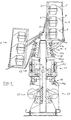
- the machine according to the invention will be described in an installation comprising, arranged on either side of a common support frame, two series of identical working positions. Consequently, the same references will be used to designate the same members of two symmetrical positions. Furthermore, this installation comprises, for each working position, a single hollow spindle and three effect and core wire deliverers, but it is obvious that it is not going beyond the ambit of the invention to produce a machine of similar design comprising several successive hollow spindles and / or more or less than three core and effect wires. In addition, in accordance with the invention, the three elementary wires indifferently form a soul or effect, but it is obvious that it would not go beyond the scope of the invention to produce a similar machine in which one of the wires would constitute permanent soul.
- the creel is a conventional swiveling creel (deformable parallelogram technique), in order to facilitate the operation of placing the full reels and removing the empty reels.
- the creel (2) in the position to the right of the frame (1), the creel (2) has been shown in its normal working position while in the position located to the left of the frame (1), said creel (2 ) has been shown in its loading position.
- the wire feeders (10,11,12) and the call provider (16) of the fancy wire formed are deliverers of the positive drive type, each deliverer being mounted on a line d 'independent shafts (10a, 11a, 12a, 16a) controlled, the control being carried out by means of an electronic assembly, controlled by a programmable microprocessor whose structure and operation is clearly shown in the block diagram illustrated in FIG. 2.
- Such an electronic control headrest makes it possible, in accordance with the invention, to control the shafts (10a, 11a, 12a, 16a) so that the supplied wires (6,7,8) can indifferently form effect or soul.
- the speed of the shafts (10a, 11a, 12a) must be adjusted so that the speed of one of the call providers (10a, 11a or 12a) is indexed to the speed of the call (16a) (or the winding system 17 if the machine does not have a delivery device (16) downstream of the hollow spindle) while the other two delivery devices have, in turn, a speed greater than this calling speed but by no means inferior.
- the drive shafts (10a, 11a, 12a, 16a) as well as the drive shaft of the winding system (17) are driven individually by synchronized motors (for example with a permanent magnet) and are controlled by a computer. controlling, in numerical control, a divider + frequency converter assembly. As shown in Figure 2, each motor is controlled by a converter and a frequency divider. The intermediate power circuits of the converters are preferably connected to a single DC power supply obtained from the AC network. The speed of each of the motors is synchronous with the frequency of their respective converter; the speed setpoints are obtained from a quartz clock whose very stable frequency is divided by each of the dividers and applied -directly in digital to each converter.
- the microcomputer produces extremely precise speed ratios by continuously changing the division factor of each divider.
- a screen is associated with the assembly to allow the operator to interact with the machine.
- this spindle is a conventional spindle with individual control (motor spindle). Furthermore, in order to facilitate the effect of the wire, downstream of this hollow spindle (13), a false twist spindle is preferably driven independently of said hollow spindle.
- the machine according to the invention has numerous advantages, among which we can cite not only the possibility of producing conventional fancy yarns but also and above all new types of yarns in which the components alternately form soul and effect. .
- This machine has a very high reliability and the speed control is carried out with very high precision.
- it is not only possible to produce new products but also to work very delicate wires given the precision of the adjustments (voltage in particular) given by the control system. .
Landscapes
- Engineering & Computer Science (AREA)
- Mechanical Engineering (AREA)
- Textile Engineering (AREA)
- Yarns And Mechanical Finishing Of Yarns Or Ropes (AREA)
Claims (6)
dadurch gekennzeichnet, daß die Antriebswellen der Zubringer (10, 11, 12) des Kernfadens und des Effektfadens und des Aufwickelsystems (17) jeweils einzeln durch synchronisierte Motoren angetrieben werden, die durch einen Rechner gesteuert werden, der numerisch einen Frequenzteiler- + Frequenzwandler-Zusammenbau derart steuert, daß die genannten Fäden unterschiedslos Effekt oder Kern werden können.
Applications Claiming Priority (2)
| Application Number | Priority Date | Filing Date | Title |
|---|---|---|---|
| FR8612894A FR2603908B1 (fr) | 1986-09-11 | 1986-09-11 | Machine pour la realisation d'un nouveau type de fil fantaisie et fil fantaisie obtenu a partir d'une telle machine |
| FR8612894 | 1986-09-11 |
Publications (2)
| Publication Number | Publication Date |
|---|---|
| EP0260206A1 EP0260206A1 (de) | 1988-03-16 |
| EP0260206B1 true EP0260206B1 (de) | 1990-03-07 |
Family
ID=9338961
Family Applications (1)
| Application Number | Title | Priority Date | Filing Date |
|---|---|---|---|
| EP19870420235 Expired - Lifetime EP0260206B1 (de) | 1986-09-11 | 1987-09-08 | Maschine zur Herstellung eines neuartigen Fantasiegarns und Fantasiegarn, das auf dieser Maschine hergestellt wird |
Country Status (4)
| Country | Link |
|---|---|
| EP (1) | EP0260206B1 (de) |
| DE (1) | DE3761825D1 (de) |
| ES (1) | ES2014323B3 (de) |
| FR (1) | FR2603908B1 (de) |
Families Citing this family (9)
| Publication number | Priority date | Publication date | Assignee | Title |
|---|---|---|---|---|
| EP0356540A1 (de) * | 1988-08-30 | 1990-03-07 | Iam - Institut Für Angewandte Mikroelektronik Gmbh | Verfahren und Vorrichtung zur Bildung von Textilmustern mit Effektgarnen auf einem Wiedergabegerät |
| FR2643090A1 (fr) * | 1989-02-14 | 1990-08-17 | Icbt | Machine pour la realisation d'un fil comportant une ame extensible et une couverture constituee de filaments entrelaces autour de ladite ame |
| DE3919687A1 (de) * | 1989-04-15 | 1990-10-18 | Skf Textilmasch Komponenten | Spinnmaschine |
| EP0439659A1 (de) * | 1990-02-01 | 1991-08-07 | Iam - Institut Für Angewandte Mikroelektronik Gmbh | Verfahren und Vorrichtung zur Bildung von Textilmustern mit Effektgarnen auf eimen Wiedergabegerät |
| IT224428Z2 (it) * | 1991-02-22 | 1996-04-30 | Giesse Srl | Macchina per la fabbricazione di ciniglia, perfezionata. |
| FR2794136B1 (fr) | 1999-05-31 | 2001-11-23 | Icbt Yarn | Machine de retordage ou cablage en continu |
| DE10253341A1 (de) * | 2002-04-26 | 2003-11-13 | Volkmann Gmbh | Spulengatter für Textilmaschinen sowie Betätigungsventil zum Verstellen eines solchen Spulengatters |
| FR2875820B1 (fr) * | 2004-09-27 | 2006-11-10 | Rieter Textile Machinery Fr | Machine de retordage d'une matiere textile filiforme |
| CN110117857B (zh) * | 2019-05-29 | 2024-05-07 | 江南大学 | 一种多通道空心锭花式捻线装置及交互式非对称捻线方法 |
Family Cites Families (4)
| Publication number | Priority date | Publication date | Assignee | Title |
|---|---|---|---|---|
| FR1394784A (fr) * | 1964-01-08 | 1965-04-09 | Procédé de fabrication de fils retors élastiques et dispositif permettant de mettre en oeuvre ce procédé | |
| FR88460E (fr) * | 1965-04-13 | 1967-02-10 | Chavanoz Moulinage Retorderie | Perfectionnement à la fabrication de fil à bouclettes |
| IT1150918B (it) * | 1981-06-30 | 1986-12-17 | Saurer Allma Gmbh | Apparecchio per la produzione di un filato ad effetto |
| FR2575195B1 (fr) * | 1984-12-21 | 1988-03-18 | Lancon Pierre | Installation pour la fabrication de fils fantaisie |
-
1986
- 1986-09-11 FR FR8612894A patent/FR2603908B1/fr not_active Expired
-
1987
- 1987-09-08 DE DE8787420235T patent/DE3761825D1/de not_active Expired - Lifetime
- 1987-09-08 ES ES87420235T patent/ES2014323B3/es not_active Expired - Lifetime
- 1987-09-08 EP EP19870420235 patent/EP0260206B1/de not_active Expired - Lifetime
Also Published As
| Publication number | Publication date |
|---|---|
| ES2014323B3 (es) | 1990-07-01 |
| DE3761825D1 (de) | 1990-04-12 |
| EP0260206A1 (de) | 1988-03-16 |
| FR2603908A1 (fr) | 1988-03-18 |
| FR2603908B1 (fr) | 1988-11-18 |
Similar Documents
| Publication | Publication Date | Title |
|---|---|---|
| EP0022421B1 (de) | Verfahren und Vorrichtung zum Herstellen eines Zwirnes mit über seine Länge abwechselnder S- und Z-Drehung | |
| EP0260206A1 (de) | Maschine zur Herstellung eines neuartigen Fantasiegarns und Fantasiegarn, das auf dieser Maschine hergestellt wird | |
| EP0882146A1 (de) | Vorrichtung zur herstellung eines mischgarnes durch zusammenkuppeln von zwei falschdralltexturierten garnen | |
| EP0026149B1 (de) | Maschine zur Herstellung selbstgezwirnter Garne | |
| EP0610144B1 (de) | Verfahren und Textilmaschine zum Aufwickeln von Faden | |
| EP0815303B1 (de) | Maschine zum kontinuierlichen zwirnen oder kablieren von fäden und anschliessend ergänzender wärmebehandlung | |
| FR2521599A1 (fr) | Procede et appareil de fabrication de files ayant diverses structures | |
| FR2471428A1 (fr) | Systeme automatique d'alimentation en fil commande par courroies pour metier circulaire de bonnetterie | |
| FR2480802A1 (fr) | Dispositif de broche a double torsion | |
| FR2621605A1 (fr) | Machine pour la texturation de fils par fausse torsion et machines textiles similaires comportant des lignes d'arbres d'entrainements | |
| EP0551787B1 (de) | Maschine zur Herstellung von Umwindegarnen | |
| FR2596422A1 (fr) | Appareil pour produire des structures textiles fibreuses | |
| EP0160610B1 (de) | Vorrichtung zur Herstellung von Ziergarn | |
| EP0502828B1 (de) | Vorrichtung zur Herstellung von Chenille | |
| EP0384092B1 (de) | Maschine zur Herstellung von kablierten Zwirnen | |
| FR2643090A1 (fr) | Machine pour la realisation d'un fil comportant une ame extensible et une couverture constituee de filaments entrelaces autour de ladite ame | |
| EP0753613B1 (de) | Vorrichtung zum fortlaufenden Einbringen eines Kernfadens in ein Faserband | |
| EP0172125B1 (de) | Verfahren zur Behandlung von Textilfäden und Vorrichtung zur Ausführung dieses Verfahrens | |
| FR2775697A1 (fr) | Dispositif delivreur de fil pour machine textile de filature moulinage, texturation ou similaire | |
| FR2664911A1 (fr) | Procede et installation pour le moulinage de fils enroules sous la forme de gateaux et plus particulierement de fils de verre. | |
| FR2509759A1 (fr) | Fil texture non double de grande masse lineique et son procede de production | |
| FR2624888A1 (fr) | Machine de retordage et de cablage en continu | |
| FR2531464A1 (fr) | Machine automatique destinee a la fabrication en continu de cordons tors utilises notamment pour constituer des embrasses de rideau | |
| FR2575195A1 (fr) | Installation pour la fabrication de fils fantaisie | |
| BE509707A (de) |
Legal Events
| Date | Code | Title | Description |
|---|---|---|---|
| PUAI | Public reference made under article 153(3) epc to a published international application that has entered the european phase |
Free format text: ORIGINAL CODE: 0009012 |
|
| AK | Designated contracting states |
Kind code of ref document: A1 Designated state(s): CH DE ES IT LI |
|
| 17P | Request for examination filed |
Effective date: 19880426 |
|
| 17Q | First examination report despatched |
Effective date: 19890803 |
|
| ITF | It: translation for a ep patent filed | ||
| GRAA | (expected) grant |
Free format text: ORIGINAL CODE: 0009210 |
|
| AK | Designated contracting states |
Kind code of ref document: B1 Designated state(s): CH DE ES IT LI |
|
| REF | Corresponds to: |
Ref document number: 3761825 Country of ref document: DE Date of ref document: 19900412 |
|
| PLBE | No opposition filed within time limit |
Free format text: ORIGINAL CODE: 0009261 |
|
| STAA | Information on the status of an ep patent application or granted ep patent |
Free format text: STATUS: NO OPPOSITION FILED WITHIN TIME LIMIT |
|
| 26N | No opposition filed | ||
| PGFP | Annual fee paid to national office [announced via postgrant information from national office to epo] |
Ref country code: CH Payment date: 19910912 Year of fee payment: 5 |
|
| PGFP | Annual fee paid to national office [announced via postgrant information from national office to epo] |
Ref country code: ES Payment date: 19910917 Year of fee payment: 5 |
|
| PGFP | Annual fee paid to national office [announced via postgrant information from national office to epo] |
Ref country code: DE Payment date: 19910919 Year of fee payment: 5 |
|
| ITTA | It: last paid annual fee | ||
| PG25 | Lapsed in a contracting state [announced via postgrant information from national office to epo] |
Ref country code: ES Free format text: LAPSE BECAUSE OF THE APPLICANT RENOUNCES Effective date: 19920909 |
|
| PG25 | Lapsed in a contracting state [announced via postgrant information from national office to epo] |
Ref country code: LI Effective date: 19920930 Ref country code: CH Effective date: 19920930 |
|
| REG | Reference to a national code |
Ref country code: CH Ref legal event code: PL |
|
| PG25 | Lapsed in a contracting state [announced via postgrant information from national office to epo] |
Ref country code: DE Effective date: 19930602 |
|
| REG | Reference to a national code |
Ref country code: ES Ref legal event code: FD2A Effective date: 19991007 |
|
| PG25 | Lapsed in a contracting state [announced via postgrant information from national office to epo] |
Ref country code: IT Free format text: LAPSE BECAUSE OF NON-PAYMENT OF DUE FEES;WARNING: LAPSES OF ITALIAN PATENTS WITH EFFECTIVE DATE BEFORE 2007 MAY HAVE OCCURRED AT ANY TIME BEFORE 2007. THE CORRECT EFFECTIVE DATE MAY BE DIFFERENT FROM THE ONE RECORDED. Effective date: 20050908 |