EP0260505A2 - Dispositif de régulation pour une turbine - Google Patents
Dispositif de régulation pour une turbine Download PDFInfo
- Publication number
- EP0260505A2 EP0260505A2 EP87112597A EP87112597A EP0260505A2 EP 0260505 A2 EP0260505 A2 EP 0260505A2 EP 87112597 A EP87112597 A EP 87112597A EP 87112597 A EP87112597 A EP 87112597A EP 0260505 A2 EP0260505 A2 EP 0260505A2
- Authority
- EP
- European Patent Office
- Prior art keywords
- flow rate
- valve
- degree
- opening
- signal
- Prior art date
- Legal status (The legal status is an assumption and is not a legal conclusion. Google has not performed a legal analysis and makes no representation as to the accuracy of the status listed.)
- Granted
Links
Images


Classifications
-
- F—MECHANICAL ENGINEERING; LIGHTING; HEATING; WEAPONS; BLASTING
- F01—MACHINES OR ENGINES IN GENERAL; ENGINE PLANTS IN GENERAL; STEAM ENGINES
- F01D—NON-POSITIVE DISPLACEMENT MACHINES OR ENGINES, e.g. STEAM TURBINES
- F01D17/00—Regulating or controlling by varying flow
- F01D17/02—Arrangement of sensing elements
- F01D17/06—Arrangement of sensing elements responsive to speed
Definitions
- This invention relates to a turbine control device which compensates for non-linearity of the degree-of-opening/flow-rate characteristic of a turbine regulating valve.
- the output of a steam turbine is regulated by using a regulating valve to alter the flow rate of the steam flowing into the turbine.
- the degree-of-opening/flow-rate characteristic of the regulating valve is normally non-linear, with a differential coefficient that is a maximum at the start of opening and which tends to drop as the valve gets closer to being fully open.
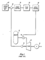
- the turbine control device is, therefore, usually provided with a function generator to compensate for this non-linearity. This will be described with reference to Fig. 1.
- Inflow of steam generated in a boiler 10 into a turbine 12 is regulated by a regulating valve 14.
- the steam that flows into the turbine 12 rotates the turbine 12, driving a generator 16 and generating electric power.
- the actual speed of the turbine 12 is detected by a speed detector 18.
- a deviation calculator 20 makes a comparative calculation with a speed value set by a speed/load setting 22. The deviation between this set speed and the actual speed is converted into a flow rate instruction by a speed controller 24 and sent to a function generator 26. Based on a preset function form, the function generator 26 converts the flow rate instruction into a valve degree-of-opening instruction, which is then sent to a servo controller 28.
- the servo controller 28 controls the degree of opening of the regulating valve 14 in accordance with this valve degree-of-opening instruction.
- the turbine 12 is controlled to a prescribed speed based on the degree of opening of the regulating valve 14.
- the function generated by the function generator 16 to compensate for the non-linearity of the degree-of-opening/flow-rate of the valve was conventionally set only with reference to the design data of the regulating valve.
- this function generator was realized by a mechanical cam or electrical polygonal line function generator, resetting to adjust to operational data was difficult, and could only be carried out after shutting down the turbine. This wastes a lot of time and reduces the life of the turbine rotor.
- One object of this invention is to provide a turbine control device including a function generator which compensates for non-linearity between the degree of opening of the regulating valve and the flow rate.
- Another object of this invention is to provide a method of controlling a turbine, whereby non-linearity between the degree of opening of the regulating valve and the flow rate can be easily and accurately compensated.
- a device for controlling a turbine which is driven by a flowing fluid comprising: means for determining a desired flow rate of the fluid; a valve for controlling the flow rate with a variable degree of opening; means for producing a signal indicative of a degree of opening of the valve; means for detecting flow rate and producing a signal indicative of the flow rate; means for sampling said degree of opening signal and said flow rate signal and memorizing a plurality of points, each indicative of a sampled detected flow rate and an actual degree of opening of the valve for producing the sampled detected flow rate; means for converting the desired flow rate into a valve degree of opening command signal based on the memorized point, and means for operating the valve according to the valve degree of opening command signal.
- a method of controlling a turbine which is driven by a flowing fluid comprising steps of: determining a desired flow rate of the fluid; controlling the flow rate with a variable degree of opening of a valve; producing a signal indicating the degree of opening of the valve; detecting flow rate of the fluid and producing a signal indicating the flow rate; memorizing a plurality of points, each indicative of a sampled detected flow rate and actual degree of opening of the valve for producing the sampled detected flow rate; converting the calculated desired flow rate into a valve degree of opening command signal based on the memorized points; and operating the valve according to the valve degree of opening command signal.
- a boiler 10 produces steam, and the steam is introduced to a turbine 12.
- the flow rate of the steam is controlled by a regulating valve 14.
- the steam that flows into the turbine 12 rotates the turbine 12, driving a generator 16 and generating electric power.
- a deviation calculator 20 makes a comparative calculation with a speed value set by a speed/load setter 22. The deviation between this set speed and the actual speed is converted into a flow rate instruction F by a speed controller 24 and sent to a function setter/generator unit 40. Based on a pre-set function, the function setter/generator unit 40 converts the flow rate instruction F into a valve degree-of-opening instruction signal y, which is then sent to a servo controller 28. The servo controller 28 controls the degree of opening of the regulating valve 14 in accordance with this valve degree-of-opening instruction. Thus, the turbine 12 is controlled to a prescribed speed based on the output of function setter/generator 40 controlling the degree of opening of the regulating valve 14.
- a power detector 42 is arranged to detect the electric power produced by the generator 16 and produce a power signal x.
- the produced power is proportional to the steam flow rate.
- the function setter/generator unit 40 has a first function generator 44, a second function generator 46, a sampling memory unit 48, a first switch 50 and a second switch 52.
- the two function generators 44 and 46 are used alternately in the two modes, and are switched between modes using the two switches 50 and 52 on a periodic basis.
- Switches 50 and 52 may be manual switches which are held in the first position during initial acceleration of the turbine and then switched manually to the second position by an operator after the turbine has reached steady state operation.
- the function generators 44 and 46 receive the flow rate instruction from the speed controller 24. With switches 50 and 52 in the positions shown in Fig. 2, only the function generator 44 is in the operational mode and gives the valve degree-of-opening instruction signal y to the servo controller 28 via the second switch 52.
- a first averaging circuit 60 produces an average of the power signal x produced by the detector 42, and its output is denoted as a mean output .
- a second averaging circuit 62 produces an average of the valve degree-of-opening instruction signal y from the function generator 44 in the operational mode, and its output is denoted as a mean degree-of-opening instruction . It should be understood that the degree-of-opening instruction signal y is being used here to indicate valve position. A signal from a sensor connected to the valve 14 to produce a signal indicating valve position could also be used.
- the mean power signal is sent to comparators 641, 642, ..., where it is compared to preset power levels, as discussed below.
- the outputs of the comparators 641, 642,... are sent, respectively, to one-shot pulse generators 661,662,..., where pulses are produced in response to the outputs of the comparators 641,642,..., respectively.
- X-registers 681,682,... store, respectively, the sampled output values x1, x2,... of the first averaging circuit 60 at the times when the respective pulses are output.
- Y-registers 701,702,... store the valve opening degree instructions y1, y2,..., which are sampled output values of the second averaging circuit 62, at the times the respective pulses are output.
- a changeover switch 72 is a multiplexer which sequentially transmits the output of the function set value combinations (x1, y1), (x2, y2),... to the function generator in the setting mode, the second function generator 46 in the case of Fig. 2.
- the first function generator 44 is in the operational mode, while the second function generator 46 is in the setting mode.
- the actual turbine speed detected by the speed detector 18 is compared with the set value of speed/load setter 22, and the speed deviation is converted to a flow rate instruction by the speed controller 24.
- This flow rate instruction is converted to a valve degree-of-opening instruction signal y by the first function generator 44 and applied to the servo controller 28 which adjusts the degree-of-opening of the regulating valve 14.
- the amount of steam supplied to the turbine 12 from the boiler 10 is adjusted so that the output of the generator 16 rises.
- the output x detected by the power detector 42 and the corresponding averaged output are thus increased from 0.
- the comparator and the one-shot pulse generator 661 come into action, so that the mean generator output x1 ( ⁇ P/3) and the mean valve degree-of-opening instruction y1 are sampled and stored in the registers 681 and 701 respectively to indicate the valve position required to give a flow rate proportional to P/3.
- the mean generator outputs x2 and x3 and the mean valve degree-of-opening instruction signals y2 and y3 are likewise successively sampled and stored in the registers 682 and 702, and 683 and 703.
- Figs. 4(a) and 4(b) show an example of the progress of this operation taking the time axis as a reference, in which the generator output signal x is linear with respect to the time axis, and the valve degree-of-opening signal y is nonlinear. Therefore, for the generator outputs x1, x2 and x3 at practically equal time intervals, the corresponding valve degree-of-opening instruction signals y1, y2, and y3 at unequal intervals are obtained.
- the multiplexer switch 72 successively transmits the respective function set values of the generator output signals x and the valve degree-of-opening instruction signal y stored in the respective registers 681, 682,... and 701, 702... to be used in the function generator in the setting mode to generate a new function.
- Function generators per se, are well-known and will not be discussed in detail here.
- a function curve with a change of gradient at three points can, therefore, be obtained by interpolating between the points (x1, y1), (x2, y2),.... obtained by correlating the generator output signal x, and the valve degree-of-opening instruction signal y.
- This curve is updated periodically and used by the function generators to produce a new valve degree-of-opening signal y.
- sampling using three points at equal intervals has been taken as an example, if required, sampling at unequal intervals or at a larger number of points can be performed by exactly the same technique.
- the method of obtained a function from the sampled values obtained is of course not restricted to the linear interpolation method shown in this embodiment. A higher order function could be used to interpolate between these points.
- the generator output is used as the signal corresponding to the flow rate.
- other signals which are proportional or linear to the flow rate such as the steam pressure of the first stage of the turbine, the reheated steam pressure, or a mean steam flow rate signal.
Landscapes
- Engineering & Computer Science (AREA)
- Mechanical Engineering (AREA)
- General Engineering & Computer Science (AREA)
- Control Of Turbines (AREA)
Applications Claiming Priority (2)
| Application Number | Priority Date | Filing Date | Title |
|---|---|---|---|
| JP61210750A JPH0643802B2 (ja) | 1986-09-09 | 1986-09-09 | タ−ビン制御装置 |
| JP210750/86 | 1986-09-09 |
Publications (3)
| Publication Number | Publication Date |
|---|---|
| EP0260505A2 true EP0260505A2 (fr) | 1988-03-23 |
| EP0260505A3 EP0260505A3 (en) | 1989-07-12 |
| EP0260505B1 EP0260505B1 (fr) | 1992-03-04 |
Family
ID=16594505
Family Applications (1)
| Application Number | Title | Priority Date | Filing Date |
|---|---|---|---|
| EP87112597A Expired EP0260505B1 (fr) | 1986-09-09 | 1987-08-28 | Dispositif de régulation pour une turbine |
Country Status (5)
| Country | Link |
|---|---|
| US (1) | US4798513A (fr) |
| EP (1) | EP0260505B1 (fr) |
| JP (1) | JPH0643802B2 (fr) |
| CA (1) | CA1293311C (fr) |
| DE (1) | DE3777037D1 (fr) |
Families Citing this family (4)
| Publication number | Priority date | Publication date | Assignee | Title |
|---|---|---|---|---|
| DE4217625A1 (de) * | 1992-05-27 | 1993-12-02 | Siemens Ag | Verfahren zur Regelung einer Turbinen-Generator-Anordnung |
| JP5823302B2 (ja) * | 2012-01-17 | 2015-11-25 | 株式会社東芝 | 蒸気タービン制御装置 |
| CN114992152B (zh) * | 2022-06-15 | 2024-12-06 | 势加透博(北京)科技有限公司 | 微型涡轮风机的测试方法 |
| JP2024075429A (ja) * | 2022-11-22 | 2024-06-03 | 株式会社日立製作所 | 発電用タービン制御装置および方法 |
Family Cites Families (7)
| Publication number | Priority date | Publication date | Assignee | Title |
|---|---|---|---|---|
| GB1413791A (en) * | 1971-11-17 | 1975-11-12 | Rolls Royce | Control systems |
| US4267458A (en) * | 1972-04-26 | 1981-05-12 | Westinghouse Electric Corp. | System and method for starting, synchronizing and operating a steam turbine with digital computer control |
| US3906196A (en) * | 1973-10-17 | 1975-09-16 | Industrial Nucleonics Corp | Non-linear feedback controller |
| DE3105376C2 (de) * | 1981-02-14 | 1984-08-23 | M.A.N. Maschinenfabrik Augsburg-Nürnberg AG, 4200 Oberhausen | Verfahren zum Betreiben von Turboverdichtern |
| JPH0612483B2 (ja) * | 1981-10-18 | 1994-02-16 | 株式会社東芝 | プロセスコントロ−ルシステム |
| US4603394A (en) * | 1984-07-30 | 1986-07-29 | Westinghouse Electric Corp. | Microprocessor-based extraction turbine control |
| US4687410A (en) * | 1985-08-19 | 1987-08-18 | General Electric Company | Torque limiter for prime mover |
-
1986
- 1986-09-09 JP JP61210750A patent/JPH0643802B2/ja not_active Expired - Lifetime
-
1987
- 1987-08-28 DE DE8787112597T patent/DE3777037D1/de not_active Expired - Lifetime
- 1987-08-28 EP EP87112597A patent/EP0260505B1/fr not_active Expired
- 1987-08-31 US US07/091,026 patent/US4798513A/en not_active Expired - Lifetime
- 1987-09-08 CA CA000546335A patent/CA1293311C/fr not_active Expired - Lifetime
Also Published As
| Publication number | Publication date |
|---|---|
| EP0260505A3 (en) | 1989-07-12 |
| US4798513A (en) | 1989-01-17 |
| EP0260505B1 (fr) | 1992-03-04 |
| CA1293311C (fr) | 1991-12-17 |
| JPS6368703A (ja) | 1988-03-28 |
| DE3777037D1 (de) | 1992-04-09 |
| JPH0643802B2 (ja) | 1994-06-08 |
Similar Documents
| Publication | Publication Date | Title |
|---|---|---|
| KR0149864B1 (ko) | 터빈 제어기의 컴퓨터 보조운전방법 | |
| US3848171A (en) | Arrangement for the optimum setting of the rotor blades of water turbines | |
| EP0260505B1 (fr) | Dispositif de régulation pour une turbine | |
| US3896623A (en) | Boiler-turbine control system | |
| KR20090105065A (ko) | 저속 영역에서의 전동기 속도 제어 시스템 및 속도 제어방법 | |
| US3828737A (en) | Control system for once-through boilers | |
| Bellini et al. | A PLL-based filter for speed noise reduction in drives using a resolver transducer | |
| JPH11272335A (ja) | 位置決め制御方法とその装置 | |
| JPH05163901A (ja) | タービン制御装置とタービン制御装置用保守ツール | |
| JPH0540530A (ja) | タービンの回転数制御装置 | |
| SU1721774A1 (ru) | Способ регулировани частоты вращени ротора вентильного электродвигател | |
| JPH0338605B2 (fr) | ||
| CN1933321B (zh) | 原动机输出的控制装置 | |
| JP2001116206A (ja) | 給水制御装置 | |
| SU801215A1 (ru) | Способ регулировани тока вентильногоэлЕКТРОпРиВОдА пОСТО ННОгО ТОКАи уСТРОйСТВО дл ЕгО ОСущЕСТВлЕНи | |
| JP2818322B2 (ja) | 蒸気タービン制御装置 | |
| SU1016772A1 (ru) | Устройство дл программного регулировани | |
| KR20020028857A (ko) | 제너레이터 출력의 예측 제어 | |
| JPS6363736B2 (fr) | ||
| JPH08296546A (ja) | ランナベーン制御装置 | |
| JPH04368500A (ja) | 発電機制御装置 | |
| JPH06117202A (ja) | 蒸気タ−ビン入口圧力制御装置 | |
| SU779179A1 (ru) | Система дистанционного автоматизированного управлени режимами работы комплекса "главный" судовой турбоагрегат-винт регулируемого шага- навешенный генератор | |
| JP2002250270A (ja) | 水力発電所の自動負荷調整装置および自動負荷調整方法 | |
| JPS63284603A (ja) | プロセスプラント制御装置 |
Legal Events
| Date | Code | Title | Description |
|---|---|---|---|
| PUAI | Public reference made under article 153(3) epc to a published international application that has entered the european phase |
Free format text: ORIGINAL CODE: 0009012 |
|
| AK | Designated contracting states |
Kind code of ref document: A2 Designated state(s): CH DE FR LI SE |
|
| RIN1 | Information on inventor provided before grant (corrected) |
Inventor name: TONE, YOUICHI C/O PATENT DIVISION |
|
| PUAL | Search report despatched |
Free format text: ORIGINAL CODE: 0009013 |
|
| AK | Designated contracting states |
Kind code of ref document: A3 Designated state(s): CH DE FR LI SE |
|
| 17P | Request for examination filed |
Effective date: 19891223 |
|
| 17Q | First examination report despatched |
Effective date: 19910124 |
|
| GRAA | (expected) grant |
Free format text: ORIGINAL CODE: 0009210 |
|
| AK | Designated contracting states |
Kind code of ref document: B1 Designated state(s): CH DE FR LI SE |
|
| REF | Corresponds to: |
Ref document number: 3777037 Country of ref document: DE Date of ref document: 19920409 |
|
| ET | Fr: translation filed | ||
| PLBE | No opposition filed within time limit |
Free format text: ORIGINAL CODE: 0009261 |
|
| STAA | Information on the status of an ep patent application or granted ep patent |
Free format text: STATUS: NO OPPOSITION FILED WITHIN TIME LIMIT |
|
| 26N | No opposition filed | ||
| EAL | Se: european patent in force in sweden |
Ref document number: 87112597.7 |
|
| PGFP | Annual fee paid to national office [announced via postgrant information from national office to epo] |
Ref country code: SE Payment date: 19990804 Year of fee payment: 13 |
|
| PG25 | Lapsed in a contracting state [announced via postgrant information from national office to epo] |
Ref country code: SE Free format text: LAPSE BECAUSE OF NON-PAYMENT OF DUE FEES Effective date: 20000829 |
|
| EUG | Se: european patent has lapsed |
Ref document number: 87112597.7 |
|
| PGFP | Annual fee paid to national office [announced via postgrant information from national office to epo] |
Ref country code: CH Payment date: 20020831 Year of fee payment: 16 |
|
| PGFP | Annual fee paid to national office [announced via postgrant information from national office to epo] |
Ref country code: DE Payment date: 20020904 Year of fee payment: 16 |
|
| PGFP | Annual fee paid to national office [announced via postgrant information from national office to epo] |
Ref country code: FR Payment date: 20030808 Year of fee payment: 17 |
|
| PG25 | Lapsed in a contracting state [announced via postgrant information from national office to epo] |
Ref country code: LI Free format text: LAPSE BECAUSE OF NON-PAYMENT OF DUE FEES Effective date: 20030831 Ref country code: CH Free format text: LAPSE BECAUSE OF NON-PAYMENT OF DUE FEES Effective date: 20030831 |
|
| PG25 | Lapsed in a contracting state [announced via postgrant information from national office to epo] |
Ref country code: DE Free format text: LAPSE BECAUSE OF NON-PAYMENT OF DUE FEES Effective date: 20040302 |
|
| REG | Reference to a national code |
Ref country code: CH Ref legal event code: PL |
|
| PG25 | Lapsed in a contracting state [announced via postgrant information from national office to epo] |
Ref country code: FR Free format text: LAPSE BECAUSE OF NON-PAYMENT OF DUE FEES Effective date: 20050429 |
|
| REG | Reference to a national code |
Ref country code: FR Ref legal event code: ST |